EP3041623B1 - Procédé permettant de démouler d'un moule une pièce moulée à partir d'un métal léger fondu - Google Patents
Procédé permettant de démouler d'un moule une pièce moulée à partir d'un métal léger fondu Download PDFInfo
- Publication number
- EP3041623B1 EP3041623B1 EP13756497.7A EP13756497A EP3041623B1 EP 3041623 B1 EP3041623 B1 EP 3041623B1 EP 13756497 A EP13756497 A EP 13756497A EP 3041623 B1 EP3041623 B1 EP 3041623B1
- Authority
- EP
- European Patent Office
- Prior art keywords
- casting
- core
- passage
- cores
- furnace
- Prior art date
- Legal status (The legal status is an assumption and is not a legal conclusion. Google has not performed a legal analysis and makes no representation as to the accuracy of the status listed.)
- Active
Links
Images


Classifications
-
- B—PERFORMING OPERATIONS; TRANSPORTING
- B22—CASTING; POWDER METALLURGY
- B22D—CASTING OF METALS; CASTING OF OTHER SUBSTANCES BY THE SAME PROCESSES OR DEVICES
- B22D29/00—Removing castings from moulds, not restricted to casting processes covered by a single main group; Removing cores; Handling ingots
- B22D29/001—Removing cores
- B22D29/003—Removing cores using heat
-
- B—PERFORMING OPERATIONS; TRANSPORTING
- B22—CASTING; POWDER METALLURGY
- B22D—CASTING OF METALS; CASTING OF OTHER SUBSTANCES BY THE SAME PROCESSES OR DEVICES
- B22D21/00—Casting non-ferrous metals or metallic compounds so far as their metallurgical properties are of importance for the casting procedure; Selection of compositions therefor
- B22D21/002—Castings of light metals
- B22D21/007—Castings of light metals with low melting point, e.g. Al 659 degrees C, Mg 650 degrees C
-
- B—PERFORMING OPERATIONS; TRANSPORTING
- B22—CASTING; POWDER METALLURGY
- B22D—CASTING OF METALS; CASTING OF OTHER SUBSTANCES BY THE SAME PROCESSES OR DEVICES
- B22D25/00—Special casting characterised by the nature of the product
- B22D25/02—Special casting characterised by the nature of the product by its peculiarity of shape; of works of art
-
- B—PERFORMING OPERATIONS; TRANSPORTING
- B22—CASTING; POWDER METALLURGY
- B22D—CASTING OF METALS; CASTING OF OTHER SUBSTANCES BY THE SAME PROCESSES OR DEVICES
- B22D27/00—Treating the metal in the mould while it is molten or ductile ; Pressure or vacuum casting
- B22D27/04—Influencing the temperature of the metal, e.g. by heating or cooling the mould
-
- B—PERFORMING OPERATIONS; TRANSPORTING
- B22—CASTING; POWDER METALLURGY
- B22D—CASTING OF METALS; CASTING OF OTHER SUBSTANCES BY THE SAME PROCESSES OR DEVICES
- B22D33/00—Equipment for handling moulds
-
- C—CHEMISTRY; METALLURGY
- C21—METALLURGY OF IRON
- C21D—MODIFYING THE PHYSICAL STRUCTURE OF FERROUS METALS; GENERAL DEVICES FOR HEAT TREATMENT OF FERROUS OR NON-FERROUS METALS OR ALLOYS; MAKING METAL MALLEABLE, e.g. BY DECARBURISATION OR TEMPERING
- C21D1/00—General methods or devices for heat treatment, e.g. annealing, hardening, quenching or tempering
- C21D1/26—Methods of annealing
-
- C—CHEMISTRY; METALLURGY
- C21—METALLURGY OF IRON
- C21D—MODIFYING THE PHYSICAL STRUCTURE OF FERROUS METALS; GENERAL DEVICES FOR HEAT TREATMENT OF FERROUS OR NON-FERROUS METALS OR ALLOYS; MAKING METAL MALLEABLE, e.g. BY DECARBURISATION OR TEMPERING
- C21D9/00—Heat treatment, e.g. annealing, hardening, quenching or tempering, adapted for particular articles; Furnaces therefor
- C21D9/0068—Heat treatment, e.g. annealing, hardening, quenching or tempering, adapted for particular articles; Furnaces therefor for particular articles not mentioned below
-
- C—CHEMISTRY; METALLURGY
- C22—METALLURGY; FERROUS OR NON-FERROUS ALLOYS; TREATMENT OF ALLOYS OR NON-FERROUS METALS
- C22F—CHANGING THE PHYSICAL STRUCTURE OF NON-FERROUS METALS AND NON-FERROUS ALLOYS
- C22F1/00—Changing the physical structure of non-ferrous metals or alloys by heat treatment or by hot or cold working
- C22F1/04—Changing the physical structure of non-ferrous metals or alloys by heat treatment or by hot or cold working of aluminium or alloys based thereon
-
- B—PERFORMING OPERATIONS; TRANSPORTING
- B22—CASTING; POWDER METALLURGY
- B22D—CASTING OF METALS; CASTING OF OTHER SUBSTANCES BY THE SAME PROCESSES OR DEVICES
- B22D29/00—Removing castings from moulds, not restricted to casting processes covered by a single main group; Removing cores; Handling ingots
Definitions
- the invention relates to a method for demolding a cast from a light metal melt casting from a mold.
- the casting mold comprises at least one casting core which, in the casting, depicts a passage opening connecting two outer sides of the casting and is made of a molding material which is bonded by means of a binder which decomposes under the influence of temperature.
- the mold is subjected to a heat treatment in an oven, in which it is heated to a temperature at which the binder of the casting core loses its binding effect.
- a method of this kind is described in the WO 2004/014581 A2 described.
- thermal Entsanden known methods are used in practice, especially in the casting of engine blocks or cylinder heads for internal combustion engines made of light metal on a large scale. Castings of this type are often poured because of their usually complex filigree shape in molds, which are composed as a so-called “core package” of a variety of each prefabricated from molding material single cores. Molded cores are also used in chill casting, however, in order to mold channels and passage openings provided in the inner region of the respective casting.
- the molding materials from which the casting cores of the type in question are formed usually consist of a mixture of a suitable molding sand and the binder, which binds the individual particles of the molding sand together in the finished casting core and thus the required dimensional stability of molded from the molding material Kerns guaranteed.
- the molding material may contain certain additives which improve the interaction of binder and foundry sand or the behavior of the respective casting core during casting of the melt.
- the temperature at which the heat treatment carried out for the thermal desanding takes place is set so high that the binder burns completely completely in the oven. The remaining molding sand can then be processed with little effort for reuse.
- the thermal sanding can be used particularly effectively if, for example, from the DE 693 18 000 T3 ( EP 0 612 276 B1 ), the desanding of the casting and the preparation of the molding sand with a Solution annealing treatment of the casting are coupled and completed these three steps in a continuous flow in an oven.
- the debris from the castings is collected in the furnace in a sand bed which is fluidized by blowing in a stream of fluid gas in such a way that the chips of the molding sand are constantly in motion and consequently forced abrasive load quickly disintegrate into their individual sand particles.
- a passage which is formed in the casting core of the casting mold which images the through-opening is flowed through by hot gas whose temperature corresponds at least to the temperature at which the binder of the molding material loses its binding effect, so that the casting core forming the through-hole emerges Exposure of the hot gas to fragments or disintegration of individual particles of sand.
- the passage of the casting mold is arranged in the casting core which images the passage opening in such a way that it leads from a first outside to another outside of the casting mold.
- the inventively provided passage of the mold may already be present upon entry into the oven.
- the through-opening may be first by an aid, such as a thin lid of combustible material, e.g. Cardboard, sand, flammable fleece or the like.
- an aid such as a thin lid of combustible material, e.g. Cardboard, sand, flammable fleece or the like.
- a mold is used, the is formed so that the intensity with which it is exposed to the ruling in the heat treatment hot atmosphere, compared to the conventional approach is significantly increased.
- at least one passage is provided on the casting mold, via which hot gas formed from the furnace atmosphere also passes to casting cores of the casting mold lying inside the castings.
- the cores arranged in the interior of the casting are heated quickly to a temperature at which their binder loses its effect. This applies first to the casting core which is provided with the through-flow of hot gas, but also, if present, for the casting cores adjacent to it, which image further channels, cavities and the like in the casting.
- the furnace atmosphere contains oxygen, so that the hot gas passed through the passage of the casting mold provided according to the invention may also contain oxygen.
- the particular advantage of the inventively provided flow through the mold with hot gas then consists in that with the hot gas in the inner regions of the mold selectively reach greater amounts of oxygen, thereby promoting the combustion of the molding material binder and, accordingly, accelerates the disintegration of the inner casting cores and completed.
- the accelerated heating caused by the inventive direct flow from the inside of the casting cores of the casting mold with hot gas leads to increased thermal Stress in the cores, which also contribute to increased efficiency and to an optimized result of the present invention caused thermal desanding.
- the through-opening of the casting can be imaged by two or more casting cores, each having one Identify passage, wherein the passages of the cores are connected to each other and flowed through in the furnace together by hot gas.
- An example of such an embodiment is the above-mentioned mold for an engine block for an internal combustion engine, in which the respective cylinder opening is formed by one or more casting cores sitting on another casting core, which forms the crankcase of the engine block.
- all of these cores are provided with a passage, these passages are aligned optimally aligned, so that an intensive unhindered flow with hot gas is possible.
- such molds which are formed as a core package, which is composed of two or more casting cores.
- a core package may include not only cores, but in a conventional manner also cooling elements made of metal or Cromerzsand, such as cooling iron for the storage lane, the cylinder bore or other highly stressed areas of the engine.
- These include cooling molds, cooling iron plates, which can replace complete cores, and all comparable functional parts.
- liners sitting, which consist of a higher loadable material than the casting material from which the engine is poured and which define the cylinder chambers in the finished internal combustion engine, in which move the pistons of the engine in use.
- the effectiveness of the desanding of the outer casting cores of a core mold package can be further improved in that depressions are formed in the cores of the core package which form the outer side parts of the casting mold. These depressions not only save in a conventional manner molding sand and concomitantly weight of the mold, but also increases the attack surface for the hot gas. In this way, large amounts of oxygen reach deep into the core forming the respective side part, so that its binder burns completely for the most part in a shortened time.
- the casting mold is a core package
- plate-shaped side parts generally cover the casting mold at its bottom, sides and on its cover side.
- the at least one casting core which images the passage opening of the casting
- adjoins the respective outer termination the mold forming side member abuts and the passage of the through hole forming casting core is continued in the outer side part to the outer surface of the mold.
- the then flowing through the passage of the respective side part hot gas causes the adjacent to the passage areas of the side part are heated quickly, with the result that the binder present there burns accelerated and stresses that accelerate the decay of the side part.
- the per se known treatment of the molding material in which the fragments formed by the decay of the binder and falling from the casting fragments are collected and kept in the oven until the binder still contained in the fragments is burnt.
- the decomposition of the Fragments in individual molding sand particles can be assisted in a likewise known manner by keeping the collected fragments in the furnace by blowing a stream of gas into the molding material bed which is formed from the fragments in the furnace.
- the invention it is thus possible in a simple manner to corer castings faster and more efficiently thermally than is possible with conventional methods.
- the residence time or throughput time during which the respective casting mold lingers during the heat treatment required for desanding in the heat treatment furnace, can be significantly reduced.
- the solution annealing time i. E. the time over which the casting had to be kept at solution annealing temperature can be significantly reduced.
- the heat treatment times required for thermal coring and for the solution heat treatment optionally combined therewith can be reduced. This in turn makes it possible to build the furnaces needed for a run-through implementation of the method shorter and thus cheaper and operate with less energy.
- the passage provided according to the invention also saves mold material and weight, which in addition to the cost reduction achieved by the procedure according to the invention contributes.
- the cuboidal mold 1 is used for casting an engine block M for an internal combustion engine, not further shown here.
- the mold 1 is composed as a core package of a plurality of casting cores.
- the casting cores are each prepared in known manner from a molding material which has been formed as a mixture of a molding sand and an organic binder and optionally optionally added additives in a core shooter, not shown here to the casting cores, which then solidified by gassing with a reaction gas have been.
- the cores may alternatively be used with any organic core manufacturing process known in the art, such as hot box, hot box, croning, hand molding and self-curing processes without catalysts.
- the casting cores of the casting mold 1 include a casting core 2, which forms the bottom of the casting mold 1 and on which the other casting cores of the casting mold 1 are constructed, two casting cores 3, 4, one of which is assigned to one of the longitudinal sides of the casting mold 1 and the delimiting the casting mold 1 on its longitudinal sides, two casting cores 5,6, one of which is assigned to one of the end faces of the casting mold 1 and which delimit the casting mold 1 at their end faces, and a cover core 7, which closes the casting mold 1 at its upper side.
- each more depressions 8.9 are formed in the lateral end of the mold 1 on the longitudinal sides forming cores 3,4 and the lateral end of the mold 1 at the end faces forming cores 5,6 each more depressions 8.9 are formed.
- the depressions 8, 9 are arranged in this way and are sunk into the respective casting core 3 - 6 over such a depth that, on the one hand, a wall thickness remains in the region of their bottom sufficient to confine the casting space enclosed by the casting mold 1, but on the other hand between the depressions 8,9 only webs 10,11 remain with a thickness which ensures sufficient strength for the dimensional stability of the respective casting core 3 - 6, but at the same time a simple fracture of the webs 8,9 and concomitantly the respective casting core 3 - 6, when the binder of the molding material from which the cores 3 - 6 are formed becomes ineffective.
- cover core 7 four perpendicular to the flat outer top surface 12 of the cover core 7 aligned and arranged at regular intervals through holes 13 - 16 are formed, which lead from the top surface 12 in the space enclosed by the casting cores 2-7.
- the passage openings 13-16 can also be closed with a membrane-like covering layer which is connected in one piece to the surrounding core material of the cover core 7 and which, when exposed to the temperature prevailing during the heat treatment, rapidly shatters and the respective passage opening 13 - 16 releases.
- the lids E have been omitted, the free passages D1-D4 provided in accordance with the invention and designed in the manner explained below can be recognized by the casting mold 1.
- each two stacked annular casting cores 18a, 18b are seated on a central casting core 17 depicting the upper part of the crank space K of the engine block casting M in a seat provided for this purpose.
- the G cordkerncrue 18 a, 18 b, 19 a, 19 b, 20 a, 20 b and 21 a, 21 b define with their outer peripheral surfaces each one of the four cylinder chambers of the engine block casting M, of which Fig. 4 For clarity, only three cylinder chambers Z1 - Z3 are shown symbolically.
- the cylinder chambers each form a passage opening of the engine block casting M.
- the annular openings enclosed by the casting cores 18a-21b are simultaneously aligned with each other and with respect to the respective associated passage openings 13-16 of the closely associated on the associated edge of the respective upper casting core 18b, 19b 20b, 21b seated cover core 7, so that they form the continuation of the through holes 13-16.
- a further passage opening 22-25 is formed in the plate-shaped casting core 17, which is likewise arranged in alignment with the associated passage opening 13-16 of the cover core 7 ,
- the passage openings 22 - 25 each pass into a passage opening 26 - 29.
- the through-holes 26-29 are funnel-shaped in the direction of the bottom core 2 widening formed in a further casting core 30 which forms the lower part of the crank chamber K and sits on the bottom core 2.
- the passage openings 14, 23, 27 and 32 aligned with one another and aligned coaxially with a common longitudinal axis L2 arranged axially parallel to the longitudinal axis L1 together with the annular openings delimited by the casting cores 19a, 19b form a second passage D2 which is aligned and coaxial with one another a common axis-parallel to the longitudinal axis L1 arranged longitudinal axis L3 aligned through holes 15,24,28 and 33 together with the annular grooves defined by the cores 20a, 20b ring openings a third passage D3 and the mutually aligned and coaxial with a common also axially parallel to the longitudinal axis L1 arranged longitudinal axis L4 aligned passage openings 16,25,29 and 34 together with the annular openings bounded by the casting cores 21a, 21b, a fourth passage D4.
- the casting mold 1 is assembled in a first processing station from the casting cores 2 - 7, 17, 18a - 21b and 30 and further casting cores not shown here for the sake of clarity.
- the mold 1 is filled with aluminum melt.
- the mold 1 is a horizontal aligned axis of rotation aligned so that it is above and the cover core 2 arranged in the direction of gravity below.
- the mold 1 is again pivoted about the horizontally oriented pivot axis, so that now the feeder and the cover core 7 are at the top, while the feed opening of the feeder is arranged in the direction of gravity below.
- This method also referred to as "rotational casting" achieves uniform solidification of the casting in the casting mold 1.
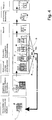
- the mold 1 runs into a continuous furnace O, in which the engine block M entsandet, the engine block M undergoes a solution annealing and falling of the engine block M molding material of the cores of the mold 1 for reprocessed.
- the casting mold 1 entering the furnace 0 is heated to the solution annealing temperature, which is typically in the range of 450-550 ° C., depending on the respectively processed Al casting alloy.
- This solution annealing temperature is higher than the temperature at which the binder of the molding material of the casting cores of the casting mold 1 burns.
- the time required for the solution annealing treatment is also completed, so that the engine block casting M can be quenched to room temperature in a station immediately thereafter. This is followed by a mechanical processing in which the feeder is separated and further machining operations are performed on the engine block M. Finally, an outsourcing treatment is optionally carried out.
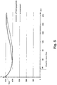
- Fig. 5 is the temperature profile of the engine block casting M in the furnace O for a gesandetes in conventional operation and solution-treated engine block casting (dashed line) and a similar in the inventive manner gesandetes and solution-annealed engine block casting (solid line) shown.
- the casting molds containing the respective casting have entered the furnace 0 after falling below the liquidus temperature of the molten aluminum from which the castings have been cast, but with the solidification of the respective engine block casting not yet completed.
- the engine block castings are passed in the only partially solidified state in the furnace 0, they can still be used in this state inherent casting heat.
- the temperature of the casting was in conventional and inventive operation when entering the furnace 0 each about 430 ° C.
- the casting gas flowed through by hot gas according to the invention has reached the solution annealing temperature TLG of approximately 485 ° C., much faster than the conventionally heated casting without casting.
- the hot-gas-flowed casting in the conventional furnace 0 lingered at the solution annealing temperature TLG for about 90 minutes longer than the conventionally treated casting. Since, at the same time, desanding was much more effective in the procedure according to the invention, the procedure according to the invention thus makes it possible to shorten the desanding and solution annealing process by about 30% compared to the conventional procedure.
Landscapes
- Engineering & Computer Science (AREA)
- Chemical & Material Sciences (AREA)
- Mechanical Engineering (AREA)
- Physics & Mathematics (AREA)
- Thermal Sciences (AREA)
- Crystallography & Structural Chemistry (AREA)
- Materials Engineering (AREA)
- Metallurgy (AREA)
- Organic Chemistry (AREA)
- Molds, Cores, And Manufacturing Methods Thereof (AREA)
- Mold Materials And Core Materials (AREA)
- Cylinder Crankcases Of Internal Combustion Engines (AREA)
Claims (10)
- Procédé permettant de démouler une pièce (M), moulée à partir d'un métal léger fondu, d'un moule (1), lequel comprend au moins un noyau de coulée (2-7, 17, 18a-21b, 30) formant dans la pièce moulée (M) une ouverture de passage (Z1-Z3) reliant deux faces extérieures de la pièce moulée, et constitué d'une matière à mouler liée au moyen d'un liant se décomposant sous l'effet de la température, étant entendu que pour démouler, le moule (1) est soumis à un traitement thermique dans un four (O), dans lequel il est chauffé à une température à laquelle le liant perd son effet liant,
caractérisé en ce qu'un passage (D1-D4) ménagé dans le noyau de coulée (18a-21b) du moule (1), formant ouverture de passage, est traversé par un gaz chaud (H) dont la température correspond au moins à la température à laquelle le liant de la matière à mouler perd son effet liant, de sorte que le noyau de coulée (18a-21b) formant l'ouverture de passage (Z1-Z3) se décompose dans le four (O), du fait de l'action du gaz chaud, en fragments (B) ou en particules de sable individuelles. - Procédé selon la revendication 1, caractérisé en ce que le passage (D1-D4) formé par le noyau de coulée (18a-21b) du moule (1) est orienté verticalement dans le four (O).
- Procédé selon l'une quelconque des revendications précédentes, caractérisé en ce que l'ouverture de passage (Z1-Z3) de la pièce moulée (1) est formée par deux noyaux de coulée ou plus (18a-21b) qui, chacun, présentent un passage (D1-D4), et en ce que les passages (D1-D4) du noyau de coulée (18a-21b) associés à une ouverture de passage (Zl-Z3) sont reliés entre eux et traversés conjointement dans le four (O) par un gaz chaud (H).
- Procédé selon l'une quelconque des revendications précédentes, caractérisé en ce que le moule (1) est constitué en tant que paquet de noyaux, formé de deux noyaux de coulée (2-7, 17, 18a-21b, 30) ou plus.
- Procédé selon la revendication 4, caractérisé en ce que des évidements (8, 9) sont formés dans les noyaux de coulée (3-6) constituant les parties latérales du moule (1).
- Procédé selon l'une quelconque des revendications précédentes, caractérisé en ce qu'au moins un noyau de coulée (18a-21b) formant l'ouverture de passage (Z1-Z3) de la pièce moulée (M) bute contre une partie latérale (7) formant la terminaison extérieure du moule (1), et en ce que le passage (D1-D4) du noyau de coulée (18a-21b) formant l'ouverture de passage (Z1-Z3) est prolongé dans la partie latérale extérieure (7), s'étend jusqu'à la surface extérieure (12) du moule (1).
- Procédé selon l'une quelconque des revendications précédentes, caractérisé en ce que le traitement thermique auquel est soumis le moule (1) dans le four (O) est réalisé en tant que traitement par recuit de mise en solution de la pièce moulée (M).
- Procédé selon l'une quelconque des revendications précédentes, caractérisé en ce que les fragments (B) formés par la désintégration du liant, et se détachant de la pièce moulée (M), sont recueillis et retenus dans le four (O), au moins ceux qui constituent l'ouverture de passage du noyau de coulée (2-7, 17, 18a-21b, 30), jusqu'à ce que le liant subsistant dans les fragments (B) soit brûlé également.
- Procédé selon l'une quelconque des revendications précédentes, caractérisé en ce que la pièce moulée (M) est un bloc moteur pour un moteur à combustion interne et en ce que l'ouverture de passage formée par au moins un noyau de coulée (18a-21b) est un orifice de cylindre (Z1-Z3) de cette pièce moulée (M).
- Procédé selon l'une quelconque des revendications précédentes, caractérisé en ce que le moule (1) et la pièce moulée (M) traversent le four (O) en un flux continu.
Applications Claiming Priority (1)
| Application Number | Priority Date | Filing Date | Title |
|---|---|---|---|
| PCT/EP2013/068277 WO2015032427A1 (fr) | 2013-09-04 | 2013-09-04 | Procédé permettant de démouler d'un moule une pièce moulée à partir d'un métal léger fondu |
Publications (2)
| Publication Number | Publication Date |
|---|---|
| EP3041623A1 EP3041623A1 (fr) | 2016-07-13 |
| EP3041623B1 true EP3041623B1 (fr) | 2017-06-07 |
Family
ID=49111211
Family Applications (1)
| Application Number | Title | Priority Date | Filing Date |
|---|---|---|---|
| EP13756497.7A Active EP3041623B1 (fr) | 2013-09-04 | 2013-09-04 | Procédé permettant de démouler d'un moule une pièce moulée à partir d'un métal léger fondu |
Country Status (10)
| Country | Link |
|---|---|
| US (1) | US9895745B2 (fr) |
| EP (1) | EP3041623B1 (fr) |
| JP (1) | JP6126746B2 (fr) |
| KR (1) | KR101759268B1 (fr) |
| CN (1) | CN105705274B (fr) |
| BR (1) | BR112016004221B1 (fr) |
| ES (1) | ES2634319T3 (fr) |
| MX (1) | MX370862B (fr) |
| RU (1) | RU2635598C2 (fr) |
| WO (1) | WO2015032427A1 (fr) |
Families Citing this family (2)
| Publication number | Priority date | Publication date | Assignee | Title |
|---|---|---|---|---|
| CN106583658B (zh) * | 2016-12-14 | 2018-11-13 | 江西腾勒动力有限公司 | 发动机缸体铸造砂芯及应用所述铸造砂芯铸造缸体的方法 |
| CN114918977B (zh) * | 2022-06-20 | 2023-10-13 | 一汽丰田发动机(长春)有限公司 | 一种机械手坐标调整标准件及取件位置确认的作业方法 |
Family Cites Families (12)
| Publication number | Priority date | Publication date | Assignee | Title |
|---|---|---|---|---|
| JPS51111421A (en) * | 1975-03-26 | 1976-10-01 | Kubota Ltd | Method of banking backup for precision casting mold |
| JPS62259661A (ja) * | 1986-05-07 | 1987-11-12 | Nissan Motor Co Ltd | 金型鋳造における中子崩壊方法 |
| EP0546210B2 (fr) * | 1991-05-24 | 2003-07-09 | Consolidated Engineering Company, Inc. | Procédé et dispositif pour le traitement thermique de pièces coulées |
| JP2849213B2 (ja) | 1992-08-13 | 1999-01-20 | コンソリデイティッド エンジニアリング カンパニー オブ ジョージア,インコーポレイテッド | 金属キャスティングの熱処理および炉内砂回収 |
| CA2254505A1 (fr) * | 1997-12-22 | 1999-06-22 | Joseph C. Schim | Formation rapide de pieces creuses complexes par la technique de moulage a cire perdue |
| CA2391349C (fr) | 1999-07-29 | 2009-09-15 | Consolidated Engineering Company, Inc. | Traitement thermique et retrait des noyaux de sable des pieces coulees |
| CA2461797A1 (fr) * | 2001-09-14 | 2003-03-27 | Bernhard Stauder | Procede de realisation de pieces moulees, sable de coulee, et son utilisation pour la mise en oeuvre du procede |
| MXPA05001393A (es) * | 2002-08-08 | 2005-04-28 | Cons Eng Co Inc | Metodos y aparatos para el tratamiento con calor y remocion de arena para fundiciones. |
| US7121318B2 (en) * | 2002-09-20 | 2006-10-17 | Alotech Ltd. Llc | Lost pattern mold removal casting method and apparatus |
| JP2006231360A (ja) * | 2005-02-24 | 2006-09-07 | Suzuki Motor Corp | 中子の分離除去方法および装置 |
| DE102005046027A1 (de) * | 2005-09-05 | 2007-03-08 | HOS Hottinger Systems GbR (vertretungsberechtigter Gesellschafter: Walter Leo Pöhlandt, 68782 Brühl) | Verfahren zum Gießen von Formteilen |
| CN102161224A (zh) * | 2011-03-11 | 2011-08-24 | 王湘冀 | 一种中空产品注塑方法、其易熔型芯及其制作方法 |
-
2013
- 2013-09-04 EP EP13756497.7A patent/EP3041623B1/fr active Active
- 2013-09-04 JP JP2016529434A patent/JP6126746B2/ja active Active
- 2013-09-04 KR KR1020167007584A patent/KR101759268B1/ko active Active
- 2013-09-04 BR BR112016004221-2A patent/BR112016004221B1/pt active IP Right Grant
- 2013-09-04 ES ES13756497.7T patent/ES2634319T3/es active Active
- 2013-09-04 CN CN201380079379.3A patent/CN105705274B/zh active Active
- 2013-09-04 US US14/916,374 patent/US9895745B2/en active Active
- 2013-09-04 WO PCT/EP2013/068277 patent/WO2015032427A1/fr not_active Ceased
- 2013-09-04 RU RU2016112524A patent/RU2635598C2/ru active
- 2013-09-04 MX MX2016002776A patent/MX370862B/es active IP Right Grant
Also Published As
| Publication number | Publication date |
|---|---|
| CN105705274B (zh) | 2017-07-25 |
| EP3041623A1 (fr) | 2016-07-13 |
| KR101759268B1 (ko) | 2017-07-18 |
| ES2634319T3 (es) | 2017-09-27 |
| WO2015032427A1 (fr) | 2015-03-12 |
| RU2635598C2 (ru) | 2017-11-14 |
| RU2016112524A (ru) | 2017-10-09 |
| BR112016004221B1 (pt) | 2019-06-11 |
| US20160193655A1 (en) | 2016-07-07 |
| US9895745B2 (en) | 2018-02-20 |
| JP6126746B2 (ja) | 2017-05-10 |
| KR20160047514A (ko) | 2016-05-02 |
| JP2016530101A (ja) | 2016-09-29 |
| MX370862B (es) | 2020-01-08 |
| CN105705274A (zh) | 2016-06-22 |
| MX2016002776A (es) | 2016-08-03 |
Similar Documents
| Publication | Publication Date | Title |
|---|---|---|
| EP2844409B1 (fr) | Procédé de coulée d'une pièce coulée munie d'au moins une ouverture de passage | |
| EP2091678B1 (fr) | Moule de coulée pour la coulée d'une pièce et utilisation de ce moule de coulée | |
| EP3597329B1 (fr) | Procédé de coulée de pièces coulées | |
| DE102014101080B3 (de) | Vorrichtung zur Herstellung eines Zylinderkurbelgehäuses im Niederdruck- oder Schwerkraftgießverfahren | |
| EP2945760B1 (fr) | Moule permettant d'obtenir des pièces en fonte, en particulier des blocs-cylindres et des culasses, avec raccordement fonctionnel de la masselotte | |
| DE102008058329A1 (de) | Verfahren zur Temperierung einer Heiß Isostatischen Presse und eine Heiß Isostatische Presse | |
| EP0872295A1 (fr) | Moule de coulage et procédé de fabrication de pièces coulées creuses et pièces coulées creuses | |
| DE102009049695A1 (de) | Verfahren zur Herstellung eines Läufers eines Turboladers | |
| EP3041623B1 (fr) | Procédé permettant de démouler d'un moule une pièce moulée à partir d'un métal léger fondu | |
| DE102008037778A1 (de) | Gießvorrichtung und Kokille für eine Gießvorrichtung | |
| DE102012019192A1 (de) | Aluminiumgusskern und Verfahren zur Herstellung eines Aluminiumgusskerns | |
| EP3166740B1 (fr) | Noyau de coulée et procédé de fabrication d'un noyau de coulée | |
| EP0890400B1 (fr) | Procédé de moulage pour la fabrication des objets moulés métalliques | |
| EP4355512B1 (fr) | Procédé de coulée de pièces moulées | |
| EP2636467B1 (fr) | Dispositif de fabrication d'un bloc moteur agencé en V | |
| EP2734322B1 (fr) | Noyau de coulée d'un moule pour la fabrication d'un cylindre | |
| DE102017106775A1 (de) | Gießkern und Verfahren zu seiner Herstellung | |
| EP3285941B1 (fr) | Boîte à noyau permettant de produire des noyaux de coulée | |
| DE102015217452A1 (de) | Verfahren zur Herstellung eines gegossenen, metallischen Lagergehäuses | |
| EP0415135A2 (fr) | Procédé de fabrication de disques de frein | |
| WO2015051991A1 (fr) | Moule de coulée et piston fabriqué au moyen de celui-ci | |
| DE102012217939A1 (de) | Verfahren zur Herstellung von Kernen für die gießtechnische Herstellung von Werkstücken | |
| EP2312063B1 (fr) | Recouvrement doté d'une surface résistante à l'usure et son procédé de fabrication | |
| DE3002576A1 (de) | Dauerform (kokille) zur herstellung von gussstuecken aus leichtmetall | |
| DE2402893C3 (de) | Verfahren zum Gießen von Metallen mit hohem Schmelzpunkt in mehrteiligen Gießformen |
Legal Events
| Date | Code | Title | Description |
|---|---|---|---|
| PUAI | Public reference made under article 153(3) epc to a published international application that has entered the european phase |
Free format text: ORIGINAL CODE: 0009012 |
|
| 17P | Request for examination filed |
Effective date: 20160229 |
|
| AK | Designated contracting states |
Kind code of ref document: A1 Designated state(s): AL AT BE BG CH CY CZ DE DK EE ES FI FR GB GR HR HU IE IS IT LI LT LU LV MC MK MT NL NO PL PT RO RS SE SI SK SM TR |
|
| AX | Request for extension of the european patent |
Extension state: BA ME |
|
| DAX | Request for extension of the european patent (deleted) | ||
| GRAP | Despatch of communication of intention to grant a patent |
Free format text: ORIGINAL CODE: EPIDOSNIGR1 |
|
| INTG | Intention to grant announced |
Effective date: 20161221 |
|
| GRAS | Grant fee paid |
Free format text: ORIGINAL CODE: EPIDOSNIGR3 |
|
| AK | Designated contracting states |
Kind code of ref document: B1 Designated state(s): AL AT BE BG CH CY CZ DE DK EE ES FI FR GB GR HR HU IE IS IT LI LT LU LV MC MK MT NL NO PL PT RO RS SE SI SK SM TR |
|
| REG | Reference to a national code |
Ref country code: GB Ref legal event code: FG4D Free format text: NOT ENGLISH |
|
| GRAA | (expected) grant |
Free format text: ORIGINAL CODE: 0009210 |
|
| REG | Reference to a national code |
Ref country code: CH Ref legal event code: EP Ref country code: AT Ref legal event code: REF Ref document number: 898849 Country of ref document: AT Kind code of ref document: T Effective date: 20170615 |
|
| REG | Reference to a national code |
Ref country code: IE Ref legal event code: FG4D Free format text: LANGUAGE OF EP DOCUMENT: GERMAN |
|
| REG | Reference to a national code |
Ref country code: DE Ref legal event code: R096 Ref document number: 502013007444 Country of ref document: DE |
|
| REG | Reference to a national code |
Ref country code: FR Ref legal event code: PLFP Year of fee payment: 5 |
|
| REG | Reference to a national code |
Ref country code: ES Ref legal event code: FG2A Ref document number: 2634319 Country of ref document: ES Kind code of ref document: T3 Effective date: 20170927 |
|
| REG | Reference to a national code |
Ref country code: NL Ref legal event code: MP Effective date: 20170607 |
|
| REG | Reference to a national code |
Ref country code: LT Ref legal event code: MG4D |
|
| PG25 | Lapsed in a contracting state [announced via postgrant information from national office to epo] |
Ref country code: LT Free format text: LAPSE BECAUSE OF FAILURE TO SUBMIT A TRANSLATION OF THE DESCRIPTION OR TO PAY THE FEE WITHIN THE PRESCRIBED TIME-LIMIT Effective date: 20170607 Ref country code: GR Free format text: LAPSE BECAUSE OF FAILURE TO SUBMIT A TRANSLATION OF THE DESCRIPTION OR TO PAY THE FEE WITHIN THE PRESCRIBED TIME-LIMIT Effective date: 20170908 Ref country code: HR Free format text: LAPSE BECAUSE OF FAILURE TO SUBMIT A TRANSLATION OF THE DESCRIPTION OR TO PAY THE FEE WITHIN THE PRESCRIBED TIME-LIMIT Effective date: 20170607 Ref country code: FI Free format text: LAPSE BECAUSE OF FAILURE TO SUBMIT A TRANSLATION OF THE DESCRIPTION OR TO PAY THE FEE WITHIN THE PRESCRIBED TIME-LIMIT Effective date: 20170607 Ref country code: NO Free format text: LAPSE BECAUSE OF FAILURE TO SUBMIT A TRANSLATION OF THE DESCRIPTION OR TO PAY THE FEE WITHIN THE PRESCRIBED TIME-LIMIT Effective date: 20170907 |
|
| PG25 | Lapsed in a contracting state [announced via postgrant information from national office to epo] |
Ref country code: NL Free format text: LAPSE BECAUSE OF FAILURE TO SUBMIT A TRANSLATION OF THE DESCRIPTION OR TO PAY THE FEE WITHIN THE PRESCRIBED TIME-LIMIT Effective date: 20170607 Ref country code: RS Free format text: LAPSE BECAUSE OF FAILURE TO SUBMIT A TRANSLATION OF THE DESCRIPTION OR TO PAY THE FEE WITHIN THE PRESCRIBED TIME-LIMIT Effective date: 20170607 Ref country code: BG Free format text: LAPSE BECAUSE OF FAILURE TO SUBMIT A TRANSLATION OF THE DESCRIPTION OR TO PAY THE FEE WITHIN THE PRESCRIBED TIME-LIMIT Effective date: 20170907 Ref country code: SE Free format text: LAPSE BECAUSE OF FAILURE TO SUBMIT A TRANSLATION OF THE DESCRIPTION OR TO PAY THE FEE WITHIN THE PRESCRIBED TIME-LIMIT Effective date: 20170607 Ref country code: LV Free format text: LAPSE BECAUSE OF FAILURE TO SUBMIT A TRANSLATION OF THE DESCRIPTION OR TO PAY THE FEE WITHIN THE PRESCRIBED TIME-LIMIT Effective date: 20170607 |
|
| PG25 | Lapsed in a contracting state [announced via postgrant information from national office to epo] |
Ref country code: CZ Free format text: LAPSE BECAUSE OF FAILURE TO SUBMIT A TRANSLATION OF THE DESCRIPTION OR TO PAY THE FEE WITHIN THE PRESCRIBED TIME-LIMIT Effective date: 20170607 Ref country code: RO Free format text: LAPSE BECAUSE OF FAILURE TO SUBMIT A TRANSLATION OF THE DESCRIPTION OR TO PAY THE FEE WITHIN THE PRESCRIBED TIME-LIMIT Effective date: 20170607 Ref country code: SK Free format text: LAPSE BECAUSE OF FAILURE TO SUBMIT A TRANSLATION OF THE DESCRIPTION OR TO PAY THE FEE WITHIN THE PRESCRIBED TIME-LIMIT Effective date: 20170607 Ref country code: EE Free format text: LAPSE BECAUSE OF FAILURE TO SUBMIT A TRANSLATION OF THE DESCRIPTION OR TO PAY THE FEE WITHIN THE PRESCRIBED TIME-LIMIT Effective date: 20170607 |
|
| PG25 | Lapsed in a contracting state [announced via postgrant information from national office to epo] |
Ref country code: IS Free format text: LAPSE BECAUSE OF FAILURE TO SUBMIT A TRANSLATION OF THE DESCRIPTION OR TO PAY THE FEE WITHIN THE PRESCRIBED TIME-LIMIT Effective date: 20171007 Ref country code: SM Free format text: LAPSE BECAUSE OF FAILURE TO SUBMIT A TRANSLATION OF THE DESCRIPTION OR TO PAY THE FEE WITHIN THE PRESCRIBED TIME-LIMIT Effective date: 20170607 Ref country code: PL Free format text: LAPSE BECAUSE OF FAILURE TO SUBMIT A TRANSLATION OF THE DESCRIPTION OR TO PAY THE FEE WITHIN THE PRESCRIBED TIME-LIMIT Effective date: 20170607 |
|
| REG | Reference to a national code |
Ref country code: DE Ref legal event code: R097 Ref document number: 502013007444 Country of ref document: DE |
|
| PLBE | No opposition filed within time limit |
Free format text: ORIGINAL CODE: 0009261 |
|
| STAA | Information on the status of an ep patent application or granted ep patent |
Free format text: STATUS: NO OPPOSITION FILED WITHIN TIME LIMIT |
|
| PG25 | Lapsed in a contracting state [announced via postgrant information from national office to epo] |
Ref country code: DK Free format text: LAPSE BECAUSE OF FAILURE TO SUBMIT A TRANSLATION OF THE DESCRIPTION OR TO PAY THE FEE WITHIN THE PRESCRIBED TIME-LIMIT Effective date: 20170607 |
|
| REG | Reference to a national code |
Ref country code: CH Ref legal event code: PL |
|
| 26N | No opposition filed |
Effective date: 20180308 |
|
| PG25 | Lapsed in a contracting state [announced via postgrant information from national office to epo] |
Ref country code: MC Free format text: LAPSE BECAUSE OF FAILURE TO SUBMIT A TRANSLATION OF THE DESCRIPTION OR TO PAY THE FEE WITHIN THE PRESCRIBED TIME-LIMIT Effective date: 20170607 |
|
| REG | Reference to a national code |
Ref country code: IE Ref legal event code: MM4A |
|
| REG | Reference to a national code |
Ref country code: BE Ref legal event code: MM Effective date: 20170930 |
|
| PG25 | Lapsed in a contracting state [announced via postgrant information from national office to epo] |
Ref country code: LU Free format text: LAPSE BECAUSE OF NON-PAYMENT OF DUE FEES Effective date: 20170904 |
|
| PG25 | Lapsed in a contracting state [announced via postgrant information from national office to epo] |
Ref country code: IE Free format text: LAPSE BECAUSE OF NON-PAYMENT OF DUE FEES Effective date: 20170904 Ref country code: CH Free format text: LAPSE BECAUSE OF NON-PAYMENT OF DUE FEES Effective date: 20170930 Ref country code: LI Free format text: LAPSE BECAUSE OF NON-PAYMENT OF DUE FEES Effective date: 20170930 |
|
| PG25 | Lapsed in a contracting state [announced via postgrant information from national office to epo] |
Ref country code: BE Free format text: LAPSE BECAUSE OF NON-PAYMENT OF DUE FEES Effective date: 20170930 |
|
| REG | Reference to a national code |
Ref country code: FR Ref legal event code: PLFP Year of fee payment: 6 |
|
| PG25 | Lapsed in a contracting state [announced via postgrant information from national office to epo] |
Ref country code: MT Free format text: LAPSE BECAUSE OF FAILURE TO SUBMIT A TRANSLATION OF THE DESCRIPTION OR TO PAY THE FEE WITHIN THE PRESCRIBED TIME-LIMIT Effective date: 20170607 |
|
| PG25 | Lapsed in a contracting state [announced via postgrant information from national office to epo] |
Ref country code: HU Free format text: LAPSE BECAUSE OF FAILURE TO SUBMIT A TRANSLATION OF THE DESCRIPTION OR TO PAY THE FEE WITHIN THE PRESCRIBED TIME-LIMIT; INVALID AB INITIO Effective date: 20130904 |
|
| PG25 | Lapsed in a contracting state [announced via postgrant information from national office to epo] |
Ref country code: SI Free format text: LAPSE BECAUSE OF FAILURE TO SUBMIT A TRANSLATION OF THE DESCRIPTION OR TO PAY THE FEE WITHIN THE PRESCRIBED TIME-LIMIT Effective date: 20170607 |
|
| PG25 | Lapsed in a contracting state [announced via postgrant information from national office to epo] |
Ref country code: CY Free format text: LAPSE BECAUSE OF FAILURE TO SUBMIT A TRANSLATION OF THE DESCRIPTION OR TO PAY THE FEE WITHIN THE PRESCRIBED TIME-LIMIT Effective date: 20170607 |
|
| REG | Reference to a national code |
Ref country code: AT Ref legal event code: MM01 Ref document number: 898849 Country of ref document: AT Kind code of ref document: T Effective date: 20180904 |
|
| PG25 | Lapsed in a contracting state [announced via postgrant information from national office to epo] |
Ref country code: MK Free format text: LAPSE BECAUSE OF FAILURE TO SUBMIT A TRANSLATION OF THE DESCRIPTION OR TO PAY THE FEE WITHIN THE PRESCRIBED TIME-LIMIT Effective date: 20170607 |
|
| PG25 | Lapsed in a contracting state [announced via postgrant information from national office to epo] |
Ref country code: AT Free format text: LAPSE BECAUSE OF NON-PAYMENT OF DUE FEES Effective date: 20180904 |
|
| PG25 | Lapsed in a contracting state [announced via postgrant information from national office to epo] |
Ref country code: PT Free format text: LAPSE BECAUSE OF FAILURE TO SUBMIT A TRANSLATION OF THE DESCRIPTION OR TO PAY THE FEE WITHIN THE PRESCRIBED TIME-LIMIT Effective date: 20170607 |
|
| PG25 | Lapsed in a contracting state [announced via postgrant information from national office to epo] |
Ref country code: AL Free format text: LAPSE BECAUSE OF FAILURE TO SUBMIT A TRANSLATION OF THE DESCRIPTION OR TO PAY THE FEE WITHIN THE PRESCRIBED TIME-LIMIT Effective date: 20170607 |
|
| PGFP | Annual fee paid to national office [announced via postgrant information from national office to epo] |
Ref country code: DE Payment date: 20250919 Year of fee payment: 13 |
|
| PGFP | Annual fee paid to national office [announced via postgrant information from national office to epo] |
Ref country code: TR Payment date: 20250901 Year of fee payment: 13 |
|
| PGFP | Annual fee paid to national office [announced via postgrant information from national office to epo] |
Ref country code: GB Payment date: 20250923 Year of fee payment: 13 |
|
| PGFP | Annual fee paid to national office [announced via postgrant information from national office to epo] |
Ref country code: FR Payment date: 20250926 Year of fee payment: 13 |
|
| PGFP | Annual fee paid to national office [announced via postgrant information from national office to epo] |
Ref country code: IT Payment date: 20250930 Year of fee payment: 13 |
|
| PGFP | Annual fee paid to national office [announced via postgrant information from national office to epo] |
Ref country code: ES Payment date: 20251020 Year of fee payment: 13 |