EP3041655B1 - Répartiteur de matière fondue à canaux froids - Google Patents
Répartiteur de matière fondue à canaux froids Download PDFInfo
- Publication number
- EP3041655B1 EP3041655B1 EP14796411.8A EP14796411A EP3041655B1 EP 3041655 B1 EP3041655 B1 EP 3041655B1 EP 14796411 A EP14796411 A EP 14796411A EP 3041655 B1 EP3041655 B1 EP 3041655B1
- Authority
- EP
- European Patent Office
- Prior art keywords
- moulding
- nozzle
- injection moulding
- nozzle block
- tool
- Prior art date
- Legal status (The legal status is an assumption and is not a legal conclusion. Google has not performed a legal analysis and makes no representation as to the accuracy of the status listed.)
- Active
Links
Images


Classifications
-
- B—PERFORMING OPERATIONS; TRANSPORTING
- B29—WORKING OF PLASTICS; WORKING OF SUBSTANCES IN A PLASTIC STATE IN GENERAL
- B29C—SHAPING OR JOINING OF PLASTICS; SHAPING OF MATERIAL IN A PLASTIC STATE, NOT OTHERWISE PROVIDED FOR; AFTER-TREATMENT OF THE SHAPED PRODUCTS, e.g. REPAIRING
- B29C45/00—Injection moulding, i.e. forcing the required volume of moulding material through a nozzle into a closed mould; Apparatus therefor
- B29C45/17—Component parts, details or accessories; Auxiliary operations
- B29C45/26—Moulds
- B29C45/27—Sprue channels ; Runner channels or runner nozzles
- B29C45/2756—Cold runner channels
Definitions
- the invention relates to a cold runner melt distributor for a casting or injection molding tool for casting or injection molding of molded parts according to the preamble of claim 1.
- the US 2012/225159 A1 as well as the WO 2013/074741 A1 describe tools comprising a plurality of mold cavities and comprising melt distributors.
- the JP 2000 043104 A describes a tool having a distributor plate and a common nozzle block, wherein the common nozzle block is spaced from front ends of nozzle openings.
- the molded parts to be cast or to be injection-molded with the cold-runner melt distributor according to the invention are to be understood in the most general sense.
- the invention includes all molding compounds which are supplied at a temperature of less than 150 ° C and then solidify in the mold cavities.
- a first example is the injection molding of silicone parts.
- the appropriate molding compound is supplied in the cold state. After the molding compound has been heated in the mold cavities, a chemical crosslinking and thus a solidification take place.
- the molding compound to be supplied has a comparatively lower temperature, while in the molding area for chemical crosslinking of the molding composition, a higher temperature prevails.
- rubber, duromers, thermosets, etc. may be provided as the molding compound.
- a second example is the use of molding compositions which are supplied in a viscous form below a temperature of 150 ° C and then cooled in the mold cavities to thereby solidify.
- An example of this would be soap, which is liquid at 80 ° C and solidifies after cooling in the mold cavity.
- soap which is liquid at 80 ° C and solidifies after cooling in the mold cavity.
- wax, food, technical metal alloys, etc. may be provided as a molding material.
- the cold runner melt distributor according to the invention is therefore intended for casting or injection molding of molded parts for molding compositions which are supplied to the mold cavity cold with a temperature of less than 150 ° C and chemically react with each other after heating within the mold cavity for solidification.
- the cold runner melt distributor according to the invention can also be used for molding compositions which are in the cold state, ie. H. be supplied to the mold cavities at a temperature below 150 ° C, without these molding compositions chemically react with each other.
- the solidification takes place by cooling.
- the known tools for casting or injection molding of molded parts have a plurality of mold cavities, which - as stated - the molding compound via a cold runner melt distributor is fed and then solidified in the molding compound.
- Each mold cavity is assigned a feed for the molding compound.
- This feed for the molding compound has a feed channel, which defines a feed nozzle at the front end and in which a valve pin is arranged.
- each feed of the molding compound assigned to the respective mold cavity is formed in a separate block. If several mold cavities are provided, the corresponding blocks are joined together with their molding material feeds.
- the disadvantage here is that so that only relatively large pitches are possible, so that the tool is overall very bulky or that for a given tool size only a very limited number of mold cavities can be accommodated.
- the basic principle is that the feeders are equipped inside the block back with a sealing ring. This serves as a seal and on the other he exerts a pressure on the cold runner for a corresponding seat in the block. Disadvantageously, the seal then always depends on the interference fit, and vice versa.
- the present invention seeks to provide a cold runner melt distributor for a casting or injection molding tool for casting or injection molding of molded parts of the type specified, in which the distance between the mold cavities is less.
- a cold runner melt distributor for a casting or injection molding tool for casting or injection molding of molded parts is created, which is characterized by small and narrow nested spacings of the molds.
- This has the advantage that the tool is very compact with its mold cavities.
- the basic idea of the cold runner melt distributor according to the invention consists in a monoblock in which the individual feeds for the molding compound are formed and accommodated to the mold cavities. This means that this nozzle block / monoblock common to all feeds has corresponding feed channels corresponding to the number of mold cavities. Thus, the nozzle block / monoblock on mutually parallel holes, which define the cold channels and in which the actual facilities of the cold runners are used.
- valve pin is arranged directly in the associated feed channel. This means that the valve pin is located directly in the corresponding hole of the nozzle block. This creates an extremely compact design.
- a second variant proposes according to claim 4, that an additional sleeve-shaped nozzle body is provided, in which the valve pin is received.
- This additional use of a nozzle body has the advantage that thereby easier cleaning is possible.
- the sealing effect is improved
- the nozzle block has tempering channels for tempering the molding compound. These tempering channels can run on a very specific way through the nozzle block, so as to achieve the desired temperature control tempering can mean cooling or heating.
- the nozzle block is defined between two plates. This is understood to mean that an outlet plate for the melt is provided in the front nozzle region, while a distributor plate is provided at the rear region of the cold channel. This rear distributor plate serves as a main distributor for the melt of the molding compound to be supplied.
- the development according to claim 6 proposes that in the front nozzle area either between the nozzle block and the front outlet plate or between the nozzle body and the front outlet plate a pressure-resistant insulating is arranged with low thermal conductivity.
- This disc can consist of a solid surface material.
- the back of the system on the one hand a tension spring, for example in the form of a plate spring and on the other hand, a sealing ring.
- a tension spring for example in the form of a plate spring and on the other hand, a sealing ring.
- the advantage in the separate use of a spring with respect to the sealing ring is that the press-in force of the cold runner can be adjusted to the cavity individually. As a result, different pressures can be built up by different spring constants, regardless of the sealing effect of the sealing ring.
- the special arrangement of the sealing ring has the advantage that the cold runner can be displaced in the axial direction.
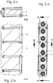
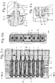
- Fig. 1 and 2 is a first embodiment and in the Fig. 3 and 4 a second embodiment of a cold runner melt distributor for a casting or injection molding tool for casting or injection molding of molded parts shown.
- the cold runner melt distributor has a nozzle block 1 as the central element.
- this nozzle block 1 according to the - not shown - form nests of the tool feed channels 2 are formed in the form of holes. These are used to supply "cold" molding compound below 150 ° C to the mold cavities.
- the nozzle block 1 is sandwiched between two plates 6, 7 fixed.
- the front outlet plate 6 defines in the region of the front end of the feed channel 2 of the nozzle block 1 each have a nozzle opening 8 which is openable and closable by means of the axially adjustable valve needle 4.
- a disc 9 in the form of a pressure-resistant insulating with low thermal conductivity.
- a spring 10 in the form of a plate spring is arranged in the region of the feed channels 2.
- a sealing ring 11 is provided between the nozzle block 1 and the rear distributor plate 7 in this area.
- This sealing ring 11 is located in the side wall region of the above-described parts.
- the nozzle block 1 has a hump-like projection and the rear distributor plate 7 a corresponding recess - or vice versa - on.
- each cold runner is assigned an additional hollow cylindrical nozzle body 12.
- the respective valve needle 4 is fixed.
- the assembly consisting of nozzle body 12 and valve needle 4 is inserted into the associated feed channel 2 of the nozzle block 1.
- the actual supply of the molding compound takes place here by the axial channel, which is formed in the hollow cylindrical nozzle body 12.
- this embodiment also has a disk 9, a spring 10 and a sealing ring 11 with respect to each cold runner. However, these are arranged between the nozzle body 12 and the front outlet plate 6 and between the nozzle body 12 and the rear distributor plate 7 in a corresponding manner.
Landscapes
- Engineering & Computer Science (AREA)
- Manufacturing & Machinery (AREA)
- Mechanical Engineering (AREA)
- Moulds For Moulding Plastics Or The Like (AREA)
- Injection Moulding Of Plastics Or The Like (AREA)
Claims (7)
- Outil de moulage ou moulage par injection pour le moulage ou moulage par injection de pièces moulées, comprenant- un répartiteur de masse fondue à canal froid et- plusieurs creux de moule auxquels une matière à mouler à une température de moins de 150°C peut être amenée par le biais du répartiteur de masse fondue à canal froid et dans lesquels la matière à mouler amenée peut ensuite être solidifiée, et- une plaque de sortie (6) qui présente une ouverture de buse (8) par creux de moule, dans lequel un canal d'amenée (2) pour l'amenée de la matière à mouler avec une aiguille de fermeture (4) disposée en son sein, pouvant être coulissée axialement, est associé à chaque creux de moule dans le répartiteur de masse fondue à canal froid,caractérisé en ce- qu'un bloc de buses commun (1) dans lequel les canaux d'amenée (2) pour la matière à mouler sont réalisés est prévu pour toutes les amenées de matière à moule,- dans lequel le bloc de buses commun (1) est fixé à la manière d'un sandwich entre une plaque de répartiteur arrière (7) pour la répartition de la masse fondue amenée de la matière à mouler et la plaque de sortie (6), et- dans lequel les canaux d'amenée (2) du bloc de buses commun (1) s'étendent chacun jusqu'aux ouvertures de buse (8) et débouchent chacun avec une extrémité avant dans les ouvertures de buse (8).
- Outil de moulage ou moulage par injection pour le moulage ou moulage par injection de pièces moulées selon la revendication 1,
caractérisé en ce
qu'un écart qui convient à mettre à disposition une fente d'aération est présent entre la plaque de sortie (6) et le bloc de buses commun (1). - Outil de moulage ou moulage par injection pour le moulage ou moulage par injection de pièces moulées selon la revendication 1 ou 2,
caractérisé en ce
que l'aiguille de fermeture (4) est directement disposée dans le canal d'amenée (2) associé. - Outil de moulage ou moulage par injection pour le moulage ou moulage par injection de pièces moulées selon la revendication 1 ou 2,
caractérisé en ce
qu'un corps de buse (12) de forme cylindrique creuse, disposé dans le canal d'amenée (2) est prévu pour la réception de l'aiguille de fermeture (4). - Outil de moulage ou moulage par injection pour le moulage ou moulage par injection de pièces moulées selon au moins une des revendications précédentes,
caractérisé en ce
que des canaux à tempérer (5) pour tempérer la matière à mouler amenée sont prévus dans le bloc de buses (1). - Outil de moulage ou moulage par injection pour le moulage ou moulage par injection de pièces moulées selon au moins une des revendications précédentes,
caractérisé en ce
qu'un disque (9) pour l'étanchéification ainsi que pour l'isolation thermique est disposé autour de l'ouverture de buse (8) entre le côté frontal avant du bloc de buses (1) et la plaque de sortie avant (6) associée ou entre le côté frontal avant du corps de buse (12) et la plaque de sortie avant (6) associée. - Outil de moulage ou moulage par injection pour le moulage ou moulage par injection de pièces moulées selon au moins une des revendications précédentes,
caractérisé en ce
qu'un ressort (10) est disposé entre le côté frontal arrière du bloc de buses (1) et la plaque de répartiteur arrière (7) associée ou entre le côté frontal arrière du corps de buse (12) et la plaque de répartiteur arrière (7) associée, et
qu'une bague d'étanchéité (11) est disposée autour d'une saillie arrière et d'un évidement correspondant à celle-ci qui sont réalisés entre le bloc de buses (1) ou le corps de buse (12) et la plaque de répartiteur arrière (7).
Applications Claiming Priority (2)
| Application Number | Priority Date | Filing Date | Title |
|---|---|---|---|
| DE102013014884.7A DE102013014884A1 (de) | 2013-09-06 | 2013-09-06 | Kaltkanal-Schmelzeverteiler |
| PCT/EP2014/002378 WO2015032490A1 (fr) | 2013-09-06 | 2014-09-02 | Répartiteur de matière fondue à canaux froids |
Publications (2)
| Publication Number | Publication Date |
|---|---|
| EP3041655A1 EP3041655A1 (fr) | 2016-07-13 |
| EP3041655B1 true EP3041655B1 (fr) | 2019-07-10 |
Family
ID=51893971
Family Applications (1)
| Application Number | Title | Priority Date | Filing Date |
|---|---|---|---|
| EP14796411.8A Active EP3041655B1 (fr) | 2013-09-06 | 2014-09-02 | Répartiteur de matière fondue à canaux froids |
Country Status (5)
| Country | Link |
|---|---|
| EP (1) | EP3041655B1 (fr) |
| DE (1) | DE102013014884A1 (fr) |
| ES (1) | ES2750263T3 (fr) |
| PT (1) | PT3041655T (fr) |
| WO (1) | WO2015032490A1 (fr) |
Families Citing this family (1)
| Publication number | Priority date | Publication date | Assignee | Title |
|---|---|---|---|---|
| CN106346712B (zh) * | 2016-11-09 | 2019-07-23 | 木林森股份有限公司 | 密集阀针式热流道系统 |
Family Cites Families (3)
| Publication number | Priority date | Publication date | Assignee | Title |
|---|---|---|---|---|
| JP2000043104A (ja) * | 1998-07-31 | 2000-02-15 | Ge Toshiba Silicones Co Ltd | 射出成形装置 |
| US8628322B2 (en) * | 2011-03-04 | 2014-01-14 | Terry L. Schwenk | Mold apparatus for use in injection molding of a liquid silicone composition |
| WO2013074741A1 (fr) * | 2011-11-18 | 2013-05-23 | Husky Injection Molding Systems Ltd. | Système d'outil de moulage comprenant un ensemble de conformation de tige |
-
2013
- 2013-09-06 DE DE102013014884.7A patent/DE102013014884A1/de not_active Withdrawn
-
2014
- 2014-09-02 PT PT147964118T patent/PT3041655T/pt unknown
- 2014-09-02 ES ES14796411T patent/ES2750263T3/es active Active
- 2014-09-02 EP EP14796411.8A patent/EP3041655B1/fr active Active
- 2014-09-02 WO PCT/EP2014/002378 patent/WO2015032490A1/fr not_active Ceased
Non-Patent Citations (1)
| Title |
|---|
| None * |
Also Published As
| Publication number | Publication date |
|---|---|
| WO2015032490A4 (fr) | 2015-05-28 |
| PT3041655T (pt) | 2019-10-25 |
| ES2750263T3 (es) | 2020-03-25 |
| EP3041655A1 (fr) | 2016-07-13 |
| WO2015032490A1 (fr) | 2015-03-12 |
| DE102013014884A1 (de) | 2015-03-12 |
Similar Documents
| Publication | Publication Date | Title |
|---|---|---|
| EP0162037B1 (fr) | Procédé pour la fabrication de pièces moulées par injection et moule par injection correspondant | |
| AT516225B1 (de) | Verfahren und Spritzgussdüse zum Herstellen von Spritzgussteilen aus Kunststoff | |
| EP2295172B1 (fr) | Unité de bloc de carotte, système de carotte et dispositif de commande pour une machine à couler sous pression | |
| DE69603538T2 (de) | Spritzgiessvorrichtung mit seitlichem Anschnitt mit radial montierten Anschnitteinsätzen | |
| DE2356764B2 (de) | Heißkanal-Spritzgießwerkzeug mit mehreren Formhohlräumen | |
| DE4422064A1 (de) | Spritzgießvorrichtung | |
| DE2744150C2 (fr) | ||
| EP3302852B1 (fr) | Système d'injection de canal chauffant pour un moule de coulée sous pression | |
| DE3912209A1 (de) | Spritzgiesseinrichtung mit duesenverschlusssystem | |
| DE10084280B3 (de) | Mehrform-Spritzgussvorrichtung mit Schmelzeaufsplittung kurz vor dem Düsenende | |
| EP2781333B1 (fr) | Composants pour un outil de moulage par injection, outil de moulage par injection et procédé de fabrication des composants | |
| DE1964109C3 (de) | Mehrteilige Spritzgießform für Formkörper aus Kunststoff, mit einem längs eines Verteilerkanals angeordneten Temperierelement | |
| EP3041655B1 (fr) | Répartiteur de matière fondue à canaux froids | |
| DE3140711A1 (de) | Mehrfachspritzgiesswerkzeug | |
| DE102009037343A1 (de) | Heißkanaldüse | |
| DE3538206A1 (de) | Warmspritzduese zur verwendung mit einer pressform zum eingusslosen spritzen von kunststoffmaterial | |
| DE102013014883A1 (de) | Kaltkanal-Schmelzeverteiler | |
| DE2542875A1 (de) | Verfahren zum angusslosen spritzen von thermoplastteilen | |
| DE112014005406B4 (de) | Spritzgießvorrichtung und Verfahren zum Spritzgießen mit einer Spritzgießvorrichtung | |
| EP3281762B1 (fr) | Machine à moulage par injection comprenant plaques d'adaptateur | |
| EP3292924B1 (fr) | Moule refroidi pour un outil | |
| DE102008018351A1 (de) | Nadelverschluss für Gusskavität | |
| DE2525437C3 (de) | Form zum Spritzgießen oder Preßspritzen von Kautschuk und anderen plastischen wärmehärtbaren Werkstoffen | |
| DE2824729A1 (de) | Spritzgussform | |
| DE10331642A1 (de) | Vorrichtung zum Spritzgießen von Formkörpern aus Kunststoff |
Legal Events
| Date | Code | Title | Description |
|---|---|---|---|
| PUAI | Public reference made under article 153(3) epc to a published international application that has entered the european phase |
Free format text: ORIGINAL CODE: 0009012 |
|
| 17P | Request for examination filed |
Effective date: 20160406 |
|
| AK | Designated contracting states |
Kind code of ref document: A1 Designated state(s): AL AT BE BG CH CY CZ DE DK EE ES FI FR GB GR HR HU IE IS IT LI LT LU LV MC MK MT NL NO PL PT RO RS SE SI SK SM TR |
|
| AX | Request for extension of the european patent |
Extension state: BA ME |
|
| DAX | Request for extension of the european patent (deleted) | ||
| STAA | Information on the status of an ep patent application or granted ep patent |
Free format text: STATUS: EXAMINATION IS IN PROGRESS |
|
| 17Q | First examination report despatched |
Effective date: 20180723 |
|
| GRAP | Despatch of communication of intention to grant a patent |
Free format text: ORIGINAL CODE: EPIDOSNIGR1 |
|
| STAA | Information on the status of an ep patent application or granted ep patent |
Free format text: STATUS: GRANT OF PATENT IS INTENDED |
|
| INTG | Intention to grant announced |
Effective date: 20190328 |
|
| GRAS | Grant fee paid |
Free format text: ORIGINAL CODE: EPIDOSNIGR3 |
|
| GRAA | (expected) grant |
Free format text: ORIGINAL CODE: 0009210 |
|
| STAA | Information on the status of an ep patent application or granted ep patent |
Free format text: STATUS: THE PATENT HAS BEEN GRANTED |
|
| AK | Designated contracting states |
Kind code of ref document: B1 Designated state(s): AL AT BE BG CH CY CZ DE DK EE ES FI FR GB GR HR HU IE IS IT LI LT LU LV MC MK MT NL NO PL PT RO RS SE SI SK SM TR |
|
| REG | Reference to a national code |
Ref country code: GB Ref legal event code: FG4D Free format text: NOT ENGLISH |
|
| REG | Reference to a national code |
Ref country code: CH Ref legal event code: EP Ref country code: AT Ref legal event code: REF Ref document number: 1153059 Country of ref document: AT Kind code of ref document: T Effective date: 20190715 |
|
| REG | Reference to a national code |
Ref country code: DE Ref legal event code: R096 Ref document number: 502014012200 Country of ref document: DE |
|
| REG | Reference to a national code |
Ref country code: IE Ref legal event code: FG4D Free format text: LANGUAGE OF EP DOCUMENT: GERMAN |
|
| REG | Reference to a national code |
Ref country code: CH Ref legal event code: NV Representative=s name: ISLER AND PEDRAZZINI AG, CH |
|
| REG | Reference to a national code |
Ref country code: PT Ref legal event code: SC4A Ref document number: 3041655 Country of ref document: PT Date of ref document: 20191025 Kind code of ref document: T Free format text: AVAILABILITY OF NATIONAL TRANSLATION Effective date: 20191003 |
|
| REG | Reference to a national code |
Ref country code: NL Ref legal event code: MP Effective date: 20190710 |
|
| REG | Reference to a national code |
Ref country code: LT Ref legal event code: MG4D |
|
| PG25 | Lapsed in a contracting state [announced via postgrant information from national office to epo] |
Ref country code: SE Free format text: LAPSE BECAUSE OF FAILURE TO SUBMIT A TRANSLATION OF THE DESCRIPTION OR TO PAY THE FEE WITHIN THE PRESCRIBED TIME-LIMIT Effective date: 20190710 Ref country code: BG Free format text: LAPSE BECAUSE OF FAILURE TO SUBMIT A TRANSLATION OF THE DESCRIPTION OR TO PAY THE FEE WITHIN THE PRESCRIBED TIME-LIMIT Effective date: 20191010 Ref country code: LT Free format text: LAPSE BECAUSE OF FAILURE TO SUBMIT A TRANSLATION OF THE DESCRIPTION OR TO PAY THE FEE WITHIN THE PRESCRIBED TIME-LIMIT Effective date: 20190710 Ref country code: NL Free format text: LAPSE BECAUSE OF FAILURE TO SUBMIT A TRANSLATION OF THE DESCRIPTION OR TO PAY THE FEE WITHIN THE PRESCRIBED TIME-LIMIT Effective date: 20190710 Ref country code: HR Free format text: LAPSE BECAUSE OF FAILURE TO SUBMIT A TRANSLATION OF THE DESCRIPTION OR TO PAY THE FEE WITHIN THE PRESCRIBED TIME-LIMIT Effective date: 20190710 Ref country code: FI Free format text: LAPSE BECAUSE OF FAILURE TO SUBMIT A TRANSLATION OF THE DESCRIPTION OR TO PAY THE FEE WITHIN THE PRESCRIBED TIME-LIMIT Effective date: 20190710 Ref country code: NO Free format text: LAPSE BECAUSE OF FAILURE TO SUBMIT A TRANSLATION OF THE DESCRIPTION OR TO PAY THE FEE WITHIN THE PRESCRIBED TIME-LIMIT Effective date: 20191010 |
|
| PG25 | Lapsed in a contracting state [announced via postgrant information from national office to epo] |
Ref country code: IS Free format text: LAPSE BECAUSE OF FAILURE TO SUBMIT A TRANSLATION OF THE DESCRIPTION OR TO PAY THE FEE WITHIN THE PRESCRIBED TIME-LIMIT Effective date: 20191110 Ref country code: LV Free format text: LAPSE BECAUSE OF FAILURE TO SUBMIT A TRANSLATION OF THE DESCRIPTION OR TO PAY THE FEE WITHIN THE PRESCRIBED TIME-LIMIT Effective date: 20190710 Ref country code: AL Free format text: LAPSE BECAUSE OF FAILURE TO SUBMIT A TRANSLATION OF THE DESCRIPTION OR TO PAY THE FEE WITHIN THE PRESCRIBED TIME-LIMIT Effective date: 20190710 Ref country code: GR Free format text: LAPSE BECAUSE OF FAILURE TO SUBMIT A TRANSLATION OF THE DESCRIPTION OR TO PAY THE FEE WITHIN THE PRESCRIBED TIME-LIMIT Effective date: 20191011 Ref country code: RS Free format text: LAPSE BECAUSE OF FAILURE TO SUBMIT A TRANSLATION OF THE DESCRIPTION OR TO PAY THE FEE WITHIN THE PRESCRIBED TIME-LIMIT Effective date: 20190710 |
|
| REG | Reference to a national code |
Ref country code: ES Ref legal event code: FG2A Ref document number: 2750263 Country of ref document: ES Kind code of ref document: T3 Effective date: 20200325 |
|
| PG25 | Lapsed in a contracting state [announced via postgrant information from national office to epo] |
Ref country code: TR Free format text: LAPSE BECAUSE OF FAILURE TO SUBMIT A TRANSLATION OF THE DESCRIPTION OR TO PAY THE FEE WITHIN THE PRESCRIBED TIME-LIMIT Effective date: 20190710 |
|
| PG25 | Lapsed in a contracting state [announced via postgrant information from national office to epo] |
Ref country code: DK Free format text: LAPSE BECAUSE OF FAILURE TO SUBMIT A TRANSLATION OF THE DESCRIPTION OR TO PAY THE FEE WITHIN THE PRESCRIBED TIME-LIMIT Effective date: 20190710 Ref country code: PL Free format text: LAPSE BECAUSE OF FAILURE TO SUBMIT A TRANSLATION OF THE DESCRIPTION OR TO PAY THE FEE WITHIN THE PRESCRIBED TIME-LIMIT Effective date: 20190710 Ref country code: EE Free format text: LAPSE BECAUSE OF FAILURE TO SUBMIT A TRANSLATION OF THE DESCRIPTION OR TO PAY THE FEE WITHIN THE PRESCRIBED TIME-LIMIT Effective date: 20190710 Ref country code: RO Free format text: LAPSE BECAUSE OF FAILURE TO SUBMIT A TRANSLATION OF THE DESCRIPTION OR TO PAY THE FEE WITHIN THE PRESCRIBED TIME-LIMIT Effective date: 20190710 Ref country code: IT Free format text: LAPSE BECAUSE OF FAILURE TO SUBMIT A TRANSLATION OF THE DESCRIPTION OR TO PAY THE FEE WITHIN THE PRESCRIBED TIME-LIMIT Effective date: 20190710 |
|
| PG25 | Lapsed in a contracting state [announced via postgrant information from national office to epo] |
Ref country code: SM Free format text: LAPSE BECAUSE OF FAILURE TO SUBMIT A TRANSLATION OF THE DESCRIPTION OR TO PAY THE FEE WITHIN THE PRESCRIBED TIME-LIMIT Effective date: 20190710 Ref country code: MC Free format text: LAPSE BECAUSE OF FAILURE TO SUBMIT A TRANSLATION OF THE DESCRIPTION OR TO PAY THE FEE WITHIN THE PRESCRIBED TIME-LIMIT Effective date: 20190710 Ref country code: IS Free format text: LAPSE BECAUSE OF FAILURE TO SUBMIT A TRANSLATION OF THE DESCRIPTION OR TO PAY THE FEE WITHIN THE PRESCRIBED TIME-LIMIT Effective date: 20200224 Ref country code: CZ Free format text: LAPSE BECAUSE OF FAILURE TO SUBMIT A TRANSLATION OF THE DESCRIPTION OR TO PAY THE FEE WITHIN THE PRESCRIBED TIME-LIMIT Effective date: 20190710 Ref country code: SK Free format text: LAPSE BECAUSE OF FAILURE TO SUBMIT A TRANSLATION OF THE DESCRIPTION OR TO PAY THE FEE WITHIN THE PRESCRIBED TIME-LIMIT Effective date: 20190710 |
|
| REG | Reference to a national code |
Ref country code: DE Ref legal event code: R097 Ref document number: 502014012200 Country of ref document: DE |
|
| PLBE | No opposition filed within time limit |
Free format text: ORIGINAL CODE: 0009261 |
|
| STAA | Information on the status of an ep patent application or granted ep patent |
Free format text: STATUS: NO OPPOSITION FILED WITHIN TIME LIMIT |
|
| PG2D | Information on lapse in contracting state deleted |
Ref country code: IS |
|
| PG25 | Lapsed in a contracting state [announced via postgrant information from national office to epo] |
Ref country code: LU Free format text: LAPSE BECAUSE OF NON-PAYMENT OF DUE FEES Effective date: 20190902 Ref country code: IE Free format text: LAPSE BECAUSE OF NON-PAYMENT OF DUE FEES Effective date: 20190902 |
|
| 26N | No opposition filed |
Effective date: 20200603 |
|
| REG | Reference to a national code |
Ref country code: BE Ref legal event code: MM Effective date: 20190930 |
|
| PG25 | Lapsed in a contracting state [announced via postgrant information from national office to epo] |
Ref country code: SI Free format text: LAPSE BECAUSE OF FAILURE TO SUBMIT A TRANSLATION OF THE DESCRIPTION OR TO PAY THE FEE WITHIN THE PRESCRIBED TIME-LIMIT Effective date: 20190710 Ref country code: BE Free format text: LAPSE BECAUSE OF NON-PAYMENT OF DUE FEES Effective date: 20190930 |
|
| GBPC | Gb: european patent ceased through non-payment of renewal fee |
Effective date: 20191010 |
|
| PG25 | Lapsed in a contracting state [announced via postgrant information from national office to epo] |
Ref country code: GB Free format text: LAPSE BECAUSE OF NON-PAYMENT OF DUE FEES Effective date: 20191010 Ref country code: FR Free format text: LAPSE BECAUSE OF NON-PAYMENT OF DUE FEES Effective date: 20190910 |
|
| PG25 | Lapsed in a contracting state [announced via postgrant information from national office to epo] |
Ref country code: CY Free format text: LAPSE BECAUSE OF FAILURE TO SUBMIT A TRANSLATION OF THE DESCRIPTION OR TO PAY THE FEE WITHIN THE PRESCRIBED TIME-LIMIT Effective date: 20190710 |
|
| PG25 | Lapsed in a contracting state [announced via postgrant information from national office to epo] |
Ref country code: HU Free format text: LAPSE BECAUSE OF FAILURE TO SUBMIT A TRANSLATION OF THE DESCRIPTION OR TO PAY THE FEE WITHIN THE PRESCRIBED TIME-LIMIT; INVALID AB INITIO Effective date: 20140902 Ref country code: MT Free format text: LAPSE BECAUSE OF FAILURE TO SUBMIT A TRANSLATION OF THE DESCRIPTION OR TO PAY THE FEE WITHIN THE PRESCRIBED TIME-LIMIT Effective date: 20190710 |
|
| PG25 | Lapsed in a contracting state [announced via postgrant information from national office to epo] |
Ref country code: MK Free format text: LAPSE BECAUSE OF FAILURE TO SUBMIT A TRANSLATION OF THE DESCRIPTION OR TO PAY THE FEE WITHIN THE PRESCRIBED TIME-LIMIT Effective date: 20190710 |
|
| PGFP | Annual fee paid to national office [announced via postgrant information from national office to epo] |
Ref country code: PT Payment date: 20240626 Year of fee payment: 11 |
|
| PGFP | Annual fee paid to national office [announced via postgrant information from national office to epo] |
Ref country code: DE Payment date: 20240523 Year of fee payment: 11 |
|
| PGFP | Annual fee paid to national office [announced via postgrant information from national office to epo] |
Ref country code: AT Payment date: 20240913 Year of fee payment: 11 |
|
| PGFP | Annual fee paid to national office [announced via postgrant information from national office to epo] |
Ref country code: ES Payment date: 20241018 Year of fee payment: 11 |
|
| PGFP | Annual fee paid to national office [announced via postgrant information from national office to epo] |
Ref country code: CH Payment date: 20241001 Year of fee payment: 11 |
|
| PG25 | Lapsed in a contracting state [announced via postgrant information from national office to epo] |
Ref country code: PT Free format text: LAPSE BECAUSE OF NON-PAYMENT OF DUE FEES Effective date: 20260302 |