EP3042419B1 - Borne de raccordement à ressort - Google Patents
Borne de raccordement à ressort Download PDFInfo
- Publication number
- EP3042419B1 EP3042419B1 EP14765889.2A EP14765889A EP3042419B1 EP 3042419 B1 EP3042419 B1 EP 3042419B1 EP 14765889 A EP14765889 A EP 14765889A EP 3042419 B1 EP3042419 B1 EP 3042419B1
- Authority
- EP
- European Patent Office
- Prior art keywords
- spring
- current bar
- clamping
- busbar piece
- terminal
- Prior art date
- Legal status (The legal status is an assumption and is not a legal conclusion. Google has not performed a legal analysis and makes no representation as to the accuracy of the status listed.)
- Active
Links
Images




Classifications
-
- H—ELECTRICITY
- H01—ELECTRIC ELEMENTS
- H01R—ELECTRICALLY-CONDUCTIVE CONNECTIONS; STRUCTURAL ASSOCIATIONS OF A PLURALITY OF MUTUALLY-INSULATED ELECTRICAL CONNECTING ELEMENTS; COUPLING DEVICES; CURRENT COLLECTORS
- H01R4/00—Electrically-conductive connections between two or more conductive members in direct contact, i.e. touching one another; Means for effecting or maintaining such contact; Electrically-conductive connections having two or more spaced connecting locations for conductors and using contact members penetrating insulation
- H01R4/28—Clamped connections, spring connections
- H01R4/48—Clamped connections, spring connections utilising a spring, clip, or other resilient member
- H01R4/4854—Clamped connections, spring connections utilising a spring, clip, or other resilient member using a wire spring
- H01R4/4863—Coil spring
-
- H—ELECTRICITY
- H01—ELECTRIC ELEMENTS
- H01R—ELECTRICALLY-CONDUCTIVE CONNECTIONS; STRUCTURAL ASSOCIATIONS OF A PLURALITY OF MUTUALLY-INSULATED ELECTRICAL CONNECTING ELEMENTS; COUPLING DEVICES; CURRENT COLLECTORS
- H01R4/00—Electrically-conductive connections between two or more conductive members in direct contact, i.e. touching one another; Means for effecting or maintaining such contact; Electrically-conductive connections having two or more spaced connecting locations for conductors and using contact members penetrating insulation
- H01R4/28—Clamped connections, spring connections
- H01R4/38—Clamped connections, spring connections utilising a clamping member acted on by screw or nut
- H01R4/40—Pivotable clamping member
-
- H—ELECTRICITY
- H01—ELECTRIC ELEMENTS
- H01R—ELECTRICALLY-CONDUCTIVE CONNECTIONS; STRUCTURAL ASSOCIATIONS OF A PLURALITY OF MUTUALLY-INSULATED ELECTRICAL CONNECTING ELEMENTS; COUPLING DEVICES; CURRENT COLLECTORS
- H01R9/00—Structural associations of a plurality of mutually-insulated electrical connecting elements, e.g. terminal strips or terminal blocks; Terminals or binding posts mounted upon a base or in a case; Bases therefor
- H01R9/22—Bases, e.g. strip, block, panel
- H01R9/24—Terminal blocks
- H01R9/26—Clip-on terminal blocks for side-by-side rail- or strip-mounting
-
- H—ELECTRICITY
- H01—ELECTRIC ELEMENTS
- H01R—ELECTRICALLY-CONDUCTIVE CONNECTIONS; STRUCTURAL ASSOCIATIONS OF A PLURALITY OF MUTUALLY-INSULATED ELECTRICAL CONNECTING ELEMENTS; COUPLING DEVICES; CURRENT COLLECTORS
- H01R9/00—Structural associations of a plurality of mutually-insulated electrical connecting elements, e.g. terminal strips or terminal blocks; Terminals or binding posts mounted upon a base or in a case; Bases therefor
- H01R9/22—Bases, e.g. strip, block, panel
- H01R9/24—Terminal blocks
- H01R9/26—Clip-on terminal blocks for side-by-side rail- or strip-mounting
- H01R9/2608—Fastening means for mounting on support rail or strip
Definitions
- the invention relates to a spring-loaded connection terminal with a busbar piece which has a base surface and sidewalls extending laterally from the base surface, wherein mutually opposite side walls delimit a receiving space on both sides, and with a clamping arrangement for clamping an electrical conductor to an associated clamping point which has at least one clamping spring. which is in operative connection with the busbar piece.
- the invention further relates to a terminal component, in particular a terminal, with a Isolierstoffgeophuse and at least one such Federkraftklemman gleich.
- DE 10 2005 058 307 A1 discloses an electrical terminal with cage tension springs, which are mounted on a busbar.
- the busbar has folded on both sides side walls, with which a lateral guidance of a guided to a terminal point electrical conductor is effected.
- a mounting foot for a mounting rail which adjoins a busbar for a spring terminal connection is also in the DE 44 09 206 C1 described.
- From the EP 2 395 605 A1 is a spring clamp and a terminal known.
- From the EP 0 871 243 A1 For example, an element for connecting a shield cable is known.
- From the JP S61 74962 U is a cage-like clamp known.
- From the GB 727 380 A Connecting devices for electrical cables are known.
- the Busbar piece itself can be made of a relatively thin and easy-to-molding material so that it is optimized for the holding function of the clamping spring and optionally for a guiding function.
- the separate current bar on the other hand, can be optimized for its primary powerline function in terms of cross-section and material selection.
- a secure receiving of the current bar while simultaneously receiving and guiding the electrical conductor to the current bar is achieved by the limited by the side walls on both sides of the receiving space. Due to the separate design of the busbar piece to an additional current bar thus a separation of functions of the two components can be achieved.
- the conductor rail piece of U-shaped cross-section does not necessarily have to be designed as an electrically conductive metal part. It can also be formed from a different material than the current bar or at least from a much thinner compared to the current bar sheet metal.
- the current bar on the side facing the bearing surface of the current bar, with which the current bar rests on the conductor bar piece has at least one protruding clamping edge. This ensures that an electrical conductor does not rest flat on the current bar, but the clamping force of the clamping spring is concentrated on a defined contact area (contact point), which is provided by the clamping edge. With the help of the above clamping edges, it is thus possible to increase the surface pressure of the electrical conductor to the current bar.
- the spring terminal has at least one U-shaped cross-section clamp, which is mounted in a direction perpendicular to the plane of the support surface of the current bar on the bus bar piece movable on the busbar piece.
- the drawbar has at least one under the current bar Crossbar. This at least one transverse web and the adjacent current bar thereby form a terminal point for clamping an electrical conductor between the transverse web and the current bar.
- a clamping spring is in operative connection with the busbar piece and the associated drawbar to exert a spring force on the drawbar, forcing the crossbar of the associated bracket in the direction of current bar. Thus, a clamping force is exerted on an electrical conductor, which is positioned between the transverse web and the current bar.
- the clamping spring may for example be a spiral compression spring.
- a spiral compression spring is placed between a head portion of the U-shaped drawbar, from which two Switzerlandbügelarme extend at a distance from each other, and the busbar piece.
- the spiral compression spring can rest either directly on the busbar piece or on a connected to the busbar piece tunnel plate.
- the clamping spring is a patch on the busbar piece cage tension.
- a cage tension spring has an abutment leg mounted on the busbar piece, a spring bow adjoining the contact leg, an actuating leg adjoining the spring bow and a clamping leg deflected by the actuating leg in the direction of the busbar piece.
- the clamping leg has a limited by a transverse web opening.
- the busbar piece protrudes through the opening together with the current bar adjacent thereto.
- the crosspiece forms together with the adjacent current bar a terminal point for clamping an electrical conductor between the crossbar and current bar.
- the busbar piece is not only taken up in the laterally limited by the side walls receiving space of the busbar piece and fixed in position there, but also secured to the busbar piece. This can be done, for example, by riveting, welding, soldering, gluing or screwing the power bar to the busbar piece.
- the current bar and the busbar piece preferably have fastening holes through which suitable fastening parts, such as rivets, screws or the like are passed. These fasteners together with the mounting holes form fasteners in the context of the present invention.
- FIG. 1 shows a side view of a first embodiment of a terminal device 1 in the form of a high-current terminal block.
- the terminal component 1 has an insulating housing 2, in which a spring-force connection terminal 3 is installed.
- the spring-force connection terminal is provided for clamping and connecting two electrical conductors (not visible), which are introduced on opposite sides into conductor insertion openings 4 of the insulating housing 2.
- the spring terminal 3 has a busbar piece which is U-shaped in cross section and has a base 6 and on both sides of the base 6 angled side walls 7. In the receiving space between the opposite side walls 7 and the base 6, an electrical conductor is received, which is inserted through an associated conductor insertion opening 4. Such an electrical conductor is then pressed by means of an associated clamping spring 8 by its spring force in the direction of the base surface 6 of the busbar piece 5.
- the right conductor terminal connection is in the open position, in which the clamping spring 8 is compressed by means of an actuating member 9 to open a clamping point for an electrical conductor.
- the nip is in this case formed by at least one clamping edge at the lower end of a U-shaped tension bow 10 and by a current bar (not visible) on the base 6 in the bounded by the side walls 7 receiving space of the busbar piece 5. It is clear that in the clamping position in the left conductor terminal of the tension bow 10 is displaced by the relaxed compression spring upwards, so that the lower free end of the tension bow 10 moves in the direction of the base 6 compared to the open position of the right conductor terminal terminal.
- the clamping spring 8 is in this embodiment, a spiral compression spring which is mounted between the base 11 of the drawbar 10 and a tunnel plate 14.
- the tunnel plate 14 is fastened with clamping straps 13 on the busbar piece 5. These clamping plates 13 engage in recesses in the side walls 7 of the busbar piece 5 in order to fix the tunnel sheet 14 with respect to their position.
- a tunnel plate spring 15 is arranged, with which a pin contact of a jumper can be received and electrically contacted between the tunnel sheet 14 and the conductor rail piece 5.
- the actuator 9 has a concentric by the clamping spring 8 extending therethrough threaded rod 16 which is rotatably mounted at the upper end to a pivot bearing 17 and in its longitudinal extension direction to the base 11 of the drawbar 10 and forms a thrust bearing.
- the threaded rod 16 dips into a corresponding threaded sleeve 18 of a clamping bush 12, which extends from the tunnel plate 14 in the direction of the base 11 of the drawbar 10 and is fastened to the tunnel plate 14.
- a screwdriver which is inserted into an actuating head 19 at the free end of the threaded rod 16 can be rotated.
- the clamping yoke 10 can be held in the open position with the aid of a locking element 20 displaceably mounted in the insulating housing 2. This locking element 20 is pressed from the outside of the insulating housing 2 in the direction of pivot bearing 17 to overlap the pivot bearing 17.
- the locking element 20 is spring-loaded by means of a compression spring 51 to achieve that the locking element 20 automatically moves back into the unlocked position (see position at the left Porterklemman gleich) when exerted by the yoke 10 and the pivot bearing 17 on the locking element 20 compressive force For example, by slightly pressing down the drawbar 10 in the direction of busbar piece 5 is reduced or canceled.
- FIG. 2 leaves a perspective view of the spring terminal 3 for the terminal device 1 from FIG. 1 detect.
- the U-shaped clamping yokes 10 have a base 11 with an opening 23 for receiving the pivot bearing 17 of the actuating member 9. From the base 11 go on both sides of the trailing arms 21, which extend with its free end under the base 6 of the busbar piece 5. At the free ends of the spring arms 21 are transverse webs 24 which engage in a below the base 6 of the busbar piece 5 arranged current bar 25 and provide a terminal point for clamping an electrical conductor between the transverse webs 24 of the clamping yoke 21 and the current bar 25.
- the traction arms 21 have a rectangular opening 26, for example, through which in particular the current bar 25 protrudes.
- protrude is meant that the current bar 25 protrudes into the opening 26, without it matters whether the free end of the current bar 25 protrudes on the opposite side of the plane of the Bucharms 21 or not.
- the busbar piece 5 can be made of a relatively thin and easily deformable sheet material, wherein it does not depend on the power line capability in the selection of materials.
- the busbar piece 5 can be formed from relatively inexpensive metal sheet or else from other, possibly also electrically insulating materials, such as fiber-reinforced plastic.
- the busbar piece 5 itself is manufactured, for example by injection molding with suitable fiber reinforcement, as a metal casting or the like.
- tunnel sheet 14 with the bearing arms 13 fixed in position is fastened to the busbar piece 5.
- the support plane of the tunnel plate 14 is spaced from the base 6 of the busbar piece 5, so that a gap for receiving the tunnel plate spring 15 (not in FIG. 2 shown) is present.
- FIG. 3 leaves a perspective view of the busbar piece 5 from FIGS. 1 and 2 detect. It is clear that the busbar piece 5 is U-shaped in cross-section and has the base 6 with on both sides thereof by 90 ° outgoing side walls 7. Over the extension length of the busbar piece 5, three successive sections of side walls 7 are provided, wherein the two outer side walls are longer than the middle side wall. On the two outer side walls are on both sides each mounting holes 27 for receiving the mounting arms 13 of the clamping bush 12 is present.
- fasteners in the form of mounting holes 28 are present.
- the current bar 25 is then fastened to the busbar piece 5 by means of rivets, screws or similar fastening elements 29 projecting through the fastening holes 28. It is also conceivable that the current bar 25 is welded in the region of the mounting holes 28 with the busbar piece 5 or possibly also glued.
- FIG. 4 lets a perspective view of the current bar 25 for the spring-loaded terminal from the FIGS. 1 to 3 detect.
- the free from the base 6 in the installed state in FIG. 3 pointing away clamping surface visible.
- clamping edges 30 are present on this clamping surface in the region of the free ends and in the direction of the center spaced thereof.
- These clamping edges 30 are arranged at the height of the current bar 25 cross-tie arms 21, so that an electrical conductor is pressed by the cross bar 24 of a pull arm 21 against the associated protruding clamping edge 30. In this way, the clamping force of the clamping spring 8 is concentrated on the clamping edge 30 with its reduced area and increases the surface pressure, ie the clamping force per unit area.
- a protrusion 31 is provided in the central region, with which a V-shaped free space between the base surface 6 of the conductor rail piece 5 and the current bar 25 is formed in cross-section.
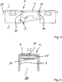
- FIG. 5 allows a side view of the busbar piece 5 with its arranged in the receiving space current bar 25 recognize. It is clear that the current bar 25 rests flat on the underside of the base 6 on the busbar piece 5. The cutting line CC is also recognizable.
- FIG. 6 leaves the busbar piece 5 in FIG. 5 recognize with arranged in its receiving space 35 current bar 25. It is clear that the width of the current bar in the embodiment is less than the distance of the opposite side walls 7 and thus less than the width of the receiving space 35 formed thereby. The busbar piece 5 is thus spaced from the side walls 7 and adjacent to the base 6 of the busbar piece 5 at. It can also be seen that the protruding clamping edges 30 face down into the receiving space 35 and thus away from the opposite base area 6 in order to form a clamping point for an electrical conductor to be clamped.
- FIG. 7 lets recognize a second embodiment of a terminal device 1 in the form of a terminal block. This is constructed in the construction of the conductor terminals with their clamping springs 8 and the tie bars 10 comparable to the first embodiment, so that reference can be made to the above.
- a difference consists in the design of the current bar, which is in two parts in this embodiment and consists of a first current bar portion 25a and a second current bar portion 25b.
- the two current bar parts 25a, 25b are bent away from the plane of the base 6 of the busbar piece 5 in the central region in alignment with the test pin opening and the test pin 34 downward from the base 6 of the busbar piece 5 and extend into this area parallel to each other and lie against each other at.
- the two adjacent sections of the current bar parts 25a, 25b are positively connected to each other, for example, by welding, riveting, caulking, locking or screwing.
- the extending away from the busbar piece 5 portions of the current bar parts 25a, 25b form support portions 37a, 37b, which are remote from the base 6 again facing away from each other with their free ends deflected.
- a support of the terminal component 1 for Auflagerung on a support rail (not shown) is provided to Auflager the support rail on the support portions 37a, 37b and the free side edges of the support rail between the support portions 37a, 37b and locking lugs 38 of a Rastfußes 39 of the terminal component 1 lock.
- FIG. 8 shows a perspective view of the spring terminal 3 for the second embodiment with the two-part current bar 25a, 25b to form a PE DIN rail connection recognize.
- an electrically conductive ground contact PE or protective conductor contact
- PE terminal a protective earth terminal
- DIN rail locking elements 41 are provided, which rest with a base 42 on the free ends of the support portions 37a, 37b of the current bar parts 25a, 25b.
- Two latching fingers 43 are then bent on the side walls of the free ends of the support portions 37a, 37b away from the busbar piece 5 down, so that arranged thereon locking lugs 38 engage under a free side edge 44 of a support rail 40. In this way, the support rail 40 is latched between the support portions 37 a, 37 b and the detents 38.
- the cross-sectionally L-shaped DIN rail locking elements 41 are overlapped by a spring clip 36, which also engages over the vertical parts 45a, 45b of the current bar parts 25a, 25b.
- the latching fingers 43 of the DIN rail locking elements 41 are acted upon by the spring force of the spring clip 36 with a mutually facing force to lock on a support rail 40.
- FIG. 9 allows a perspective view of the cross-sectionally U-shaped conductor rail piece 5 with the recorded in its receiving space 35 adjacent to the base 6 two-piece current bar 25a, 25b recognize. It is clear here that in the central area the two support sections 37a, 37b are bent away from the base 6 of the busbar section 5 parallel to the direction of the side walls 7 (downwards) and extend parallel to one another and adjacent to one another. The free ends of the support sections 37a, 37b are then deflected away from each other at a distance from the base surface 6 (at an angle of about 90 degrees +/- 10 degrees), in order to form in this way on a bearing surface for a mounting rail.
- FIG. 10 shows a perspective view of the two-part current bar with the current bar parts 25a, 25b recognize.
- the current bar sections 25a, 25b in turn have projecting clamping edges 30. It is clear that the current bar sections 25a, 25b are bent in a J-shaped cross-section, the free end of the support sections 37a, 37b being substantially shorter than the opposing clamping sections extending parallel thereto, which rest on the base 6 of the associated U-shaped busbar piece 5.
- the support sections 37a, 37b have an embossment 46 on their side facing the support rail 40 in order to reduce the contact surface with the support rail 40 and thus to increase the surface pressure for improved current transition values.
- the illustrated embodiment provides an optimally shortened current path from the clamped electrical conductor to the mounting rail 40.
- FIG. 11 shows a perspective view of a third embodiment of a spring force terminal 3 with a cage tension spring 45 recognize.
- the cage tension spring 45 in a conventional manner a bearing on the busbar piece 5 bearing leg 46, to which a spring bow 47 connects.
- the spring bow is oriented in the unactuated clamping state so that an actuating leg 48 connects to the spring bow 47 at an angle of about 45 degrees +/- 20 degrees. This extends obliquely upwards in principle in the direction of the free end of the associated current bar 25 and is there under Forming a clamping leg 49 angled so that the clamping leg 49 extends back in the direction of current bar 25.
- the clamping leg 49 has a limited by a cross bar 50 opening 51 through which the free end of the current bar 25 protrudes.
- the transverse web 50 of the clamping leg 49 then forms, together with the adjacent current bar 25, a clamping point for clamping an electrical conductor between the transverse web 50 and the current bar 25.
- Such a cage tension spring 45 can also be arranged on the opposite side. It is also conceivable that there is another terminal connection, such as a terminal connection with a clamping yoke of the first and second embodiment is formed.
Landscapes
- Connections Arranged To Contact A Plurality Of Conductors (AREA)
- Installation Of Bus-Bars (AREA)
- Connector Housings Or Holding Contact Members (AREA)
- Connections Effected By Soldering, Adhesion, Or Permanent Deformation (AREA)
- Connection Or Junction Boxes (AREA)
Claims (10)
- Borne de raccordement à ressort (3) comportant un rail de courant (5) qui présente une surface de base (6) et des parois latérales (7) partant latéralement de la surface de base (6), dans laquelle des parois latérales (7) opposées délimitent des deux côtés un espace de logement (35) destiné à loger et à guider un conducteur électrique, et comportant un système de bornes destiné à connecter le conducteur électrique à un point de serrage associé, comportant au moins un ressort de serrage (8), qui est en liaison fonctionnelle avec le rail de courant (5), au moins une barre de courant (25, 25a, 25b) introduite dans l'espace de logement (35) du rail de courant (5), qui est disposée dans l'espace de logement (35) pour former un point de serrage destiné au raccordement d'un conducteur électrique, caractérisé en ce que la barre de courant (25, 25a, 25b) est disposée séparément du rail de courant (5) et repose sur la surface de base (6).
- Borne de raccordement à ressort (3) selon la revendication 1, caractérisée en ce que la barre de courant (25, 25a, 25b) présente, du côté qui est opposé à la surface d'appui de la barre de courant (25, 25a, 25b) par laquelle la barre de courant (25, 25a, 25b) repose sur le rail de courant (5), au moins un bord de serrage (30) faisant saillie.
- Borne de raccordement à ressort (3) selon la revendication 1 ou 2, caractérisée en ce qu'au moins un étrier de serrage (10) présentant la forme d'un U en coupe transversale est monté sur le rail de courant (5) de manière à ce qu'il soit mobile sur le rail de courant (5) dans une direction perpendiculaire au plan de la surface d'appui de la barre de courant (25, 25a, 25b), dans laquelle l'étrier de serrage (10) présente au moins une tige transversale (24) s'engageant sous la barre de courant (25, 25a, 25b), dans laquelle l'au moins une tige transversale (24) et la barre de courant (25, 25a, 25b) adjacente forment un point de serrage permettant de raccorder un conducteur électrique entre la tige transversale (24) et la barre de courant (25, 25a, 25b), et dans laquelle un ressort de serrage (8) est en liaison fonctionnelle avec le rail de courant (5) et l'étrier de serrage (10) qui lui est associé afin d'exercer sur l'étrier de serrage (10), une force de ressort sollicitant la tige transversale (24) de l'étrier de serrage (10) dans la direction de la barre de courant (25, 25a, 25b).
- Borne de raccordement à ressort (3) selon la revendication 3, caractérisée en ce que le ressort de serrage (8) est un ressort de compression en spirale.
- Borne de raccordement à ressort (3) selon la revendication 1 ou 2, caractérisée en ce que le ressort de serrage (8) est un ressort à cage (45) monté sur le rail de courant (5), qui comporte une branche d'appui (46) montée sur le rail de courant (5), un coude élastique (47) relié à la branche d'appui (46), une branche d'actionnement (48) reliée au coude élastique (47) et une branche de serrage (49) écartée de la branche d'actionnement dans la direction du rail électrique (5), dans laquelle la branche de serrage (49) présente une ouverture (51) délimitée par une tige transversale (50), le rail de courant (5), en association avec la barre de courant (25, 25a, 25b) reposant sur celui-ci, fait saillie à travers l'ouverture (51), et la tige transversale (50), en association avec la barre de courant (25, 25a, 25b) adjacente, forme un point de serrage permettant de raccorder un conducteur électrique entre la tige transversale (50) et la barre de courant (25, 25a, 25b).
- Borne de raccordement à ressort (3) selon l'une des revendications précédentes, caractérisée en ce que la barre de courant (25a, 25b) est en deux parties et en ce que les deux parties de la barre de courant (25a, 25b) présentent des parties d'appui (37a, 37b) dépassant du rail de courant (5) depuis la surface d'appui vers le rail de courant (5), dans laquelle les parties d'appui (37a, 37b) forment un support permettant de fixer la borne de raccordement à ressort (3) sur un rail de support (40) et d'établir un contact électrique entre la barre de courant (25a, 25b) et le rail de support (40).
- Borne de raccordement à ressort (3) selon la revendication 6, caractérisée en ce que les parties d'appui (37a, 37b) s'étendent parallèlement l'une à l'autre et de manière à se supporter l'une l'autre depuis la zone adjacente au rail de courant (5), et en ce que les extrémités libres des parties d'appui (37a, 37b) sont écartées l'une de l'autre.
- Borne de raccordement à ressort (3) selon la revendication 7, caractérisée en ce qu'un pied d'encliquetage (39) destiné à fixer la barre de courant (25a, 25b) à un rail de support (40) est relié aux extrémités libres des parties d'appui (37a, 37b).
- Borne de raccordement à ressort (3) selon l'une des revendications précédentes, caractérisée par des éléments de fixation (28, 29) destinés à fixer l'au moins une barre de courant (25, 25a, 25b) au rail de courant (5).
- Composant de borne (1), notamment bornier de raccordement, comportant un boîtier en matériau isolant (2) et comportant au moins une borne de raccordement à ressort (3) selon l'une des revendications précédentes, dans le boîtier en matériau isolant (2), dans lequel le boîtier en matériau isolant (2) présente au moins une ouverture d'introduction de conducteur (4) qui conduit à un point de serrage associé de la borne de raccordement à ressort (3), permettant d'introduire un conducteur électrique et de raccorder le conducteur électrique introduit au point de serrage.
Applications Claiming Priority (2)
| Application Number | Priority Date | Filing Date | Title |
|---|---|---|---|
| DE102013109640.9A DE102013109640B4 (de) | 2013-09-04 | 2013-09-04 | Federkraftanschlussklemme und Klemmenbauelement |
| PCT/EP2014/068502 WO2015032718A1 (fr) | 2013-09-04 | 2014-09-01 | Borne de raccordement à ressort |
Publications (2)
| Publication Number | Publication Date |
|---|---|
| EP3042419A1 EP3042419A1 (fr) | 2016-07-13 |
| EP3042419B1 true EP3042419B1 (fr) | 2018-04-04 |
Family
ID=51539240
Family Applications (1)
| Application Number | Title | Priority Date | Filing Date |
|---|---|---|---|
| EP14765889.2A Active EP3042419B1 (fr) | 2013-09-04 | 2014-09-01 | Borne de raccordement à ressort |
Country Status (6)
| Country | Link |
|---|---|
| US (1) | US9601844B2 (fr) |
| EP (1) | EP3042419B1 (fr) |
| JP (1) | JP6423437B2 (fr) |
| CN (2) | CN110391507A (fr) |
| DE (1) | DE102013109640B4 (fr) |
| WO (1) | WO2015032718A1 (fr) |
Families Citing this family (17)
| Publication number | Priority date | Publication date | Assignee | Title |
|---|---|---|---|---|
| DE102014012873A1 (de) * | 2014-09-04 | 2016-03-24 | Auto-Kabel Management Gmbh | Verbindungselement zum elektrischen Verbinden von Flachleitern |
| DE202016102959U1 (de) * | 2016-06-02 | 2017-09-06 | Weidmüller Interface GmbH & Co. KG | Federkraftklemme für Leiter |
| DE102016010951B4 (de) * | 2016-09-09 | 2020-10-01 | WAGO Verwaltungsgesellschaft mit beschränkter Haftung | Klemme mit Kontaktplatte |
| US10176905B2 (en) * | 2016-12-08 | 2019-01-08 | Kitty Hawk Corporation | Electrically conductive and insulative composite |
| US10461444B2 (en) | 2017-01-06 | 2019-10-29 | Hubbell Incorporated | Electrical wiring devices with screwless connection terminals |
| JP6848489B2 (ja) * | 2017-02-01 | 2021-03-24 | Smk株式会社 | コンタクトおよびコネクタ |
| BE1025389B1 (de) * | 2017-07-14 | 2019-02-12 | Phoenix Contact Gmbh & Co. Kg | ANSCHLUSSEINRICHTUNG ZUM ANSCHLIEßEN EINER ELEKTRISCHEN LEITUNG |
| DE102018129949A1 (de) * | 2018-11-27 | 2020-05-28 | Phoenix Contact Gmbh & Co. Kg | Federkraftklemme zum Verbinden von Leitern |
| DE102018129950B4 (de) * | 2018-11-27 | 2025-10-09 | Phoenix Contact Gmbh & Co. Kg | Federkraftklemme zum Verbinden von Leitern |
| DE102019111159B4 (de) * | 2019-04-30 | 2023-06-07 | Phoenix Contact Gmbh & Co. Kg | Anschlussanordnung sowie Anschlussklemme |
| US11495895B2 (en) | 2019-05-01 | 2022-11-08 | Hubbell Incorporated | Terminations for electrical wiring devices |
| CN113612039B (zh) | 2021-07-21 | 2023-06-30 | 恩尼特克电子科技(深圳)有限公司 | 螺旋弹簧式锁线端子台 |
| MX2024003613A (es) | 2021-09-27 | 2024-04-09 | Hubbell Inc | Terminales de conexion sin tornillos con administrador de cables. |
| WO2023177811A1 (fr) | 2022-03-16 | 2023-09-21 | Hubbell Incorporated | Dispositifs de câblage électrique à bornes de fil sans vis |
| CN114531817A (zh) * | 2022-03-30 | 2022-05-24 | 济南正大科技发展有限公司 | 一种用于网络安全监控设备控制柜 |
| CN120858493A (zh) | 2022-11-16 | 2025-10-28 | 豪倍公司 | 具有线材端接组件的多极电气布线装置 |
| DE202024106083U1 (de) * | 2024-10-23 | 2026-03-26 | WAGO Verwaltungsgesellschaft mit beschränkter Haftung | Leiteranschlussklemme |
Family Cites Families (28)
| Publication number | Priority date | Publication date | Assignee | Title |
|---|---|---|---|---|
| GB727380A (en) | 1953-08-21 | 1955-03-30 | Garnerot & Co Cons Agencies Lt | Improvements in means for detachably securing leads to electrical connecting devices |
| US3246283A (en) * | 1963-12-23 | 1966-04-12 | Huska Paul | Accessible, self-mounting terminal block |
| US3304392A (en) * | 1965-02-11 | 1967-02-14 | Smith Corp A O | Space saving electrical terminal |
| DE1285589B (de) | 1967-05-19 | 1968-12-19 | Wago Kontakttechnik Gmbh | Schraubenlose Verbindungsklemme |
| CH456714A (de) * | 1967-11-13 | 1968-07-31 | Oskar Woertz H & O Woe | Elektrische Klemme |
| CH575180A5 (fr) * | 1975-03-25 | 1976-04-30 | Woertz Fa | |
| FR2472854A2 (fr) * | 1979-12-28 | 1981-07-03 | Alsthom Cgee | Borne de raccordement |
| JPH0247560Y2 (fr) * | 1984-10-19 | 1990-12-13 | ||
| US4832628A (en) * | 1988-05-16 | 1989-05-23 | Paul Huska | Terminal block insert device |
| DE4409206C1 (de) | 1994-03-17 | 1995-05-11 | Phoenix Contact Gmbh & Co | Fuß für eine elektrische Schutzleiterklemme sowie Schutzleiterklemme |
| DE19714634A1 (de) | 1997-04-09 | 1998-10-15 | Weidmueller Interface | Element zum Anschließen eines Schirmkabels |
| DE19817924C2 (de) * | 1998-04-17 | 2003-06-26 | Wago Verwaltungs Gmbh | Hochstromklemme mit Federkraftklemmanschluß |
| DE19818704C1 (de) | 1998-04-19 | 1999-11-04 | Wago Verwaltungs Gmbh | Montagefuß mit Schutzleiterfunktion für elektr. Klemmen |
| DE19818604C2 (de) | 1998-04-20 | 2000-05-18 | Mannesmann Ag | Vorrichtung zur Übergabe von Stückgut, insbesondere von Werkstückträgern, Werkstücken, Behältern oder Paletten |
| JP3387438B2 (ja) | 1998-06-04 | 2003-03-17 | 住友電装株式会社 | 雄型コネクタ及び雄型コネクタ用キャップ |
| DE19916755B4 (de) * | 1999-04-14 | 2007-06-28 | Weidmüller Interface Gmbh & Co. | Zugfederklemme |
| DE29919903U1 (de) * | 1999-11-12 | 2001-03-29 | Weidmüller Interface GmbH & Co, 32760 Detmold | Zugfederanschluß für große Leiterquerschnitte |
| DE202005005369U1 (de) * | 2004-11-13 | 2006-03-16 | Weidmüller Interface GmbH & Co. KG | Anschlußvorrichtung zum Direktsteckanschluß von Leiterenden und elektrisches Gerät mit einer derartigen Anschlußvorrichtung |
| DE102005058307A1 (de) | 2005-12-07 | 2007-06-14 | Wago Verwaltungsgesellschaft Mbh | Elektrische Anschlussklemme |
| DE102005060410A1 (de) * | 2005-12-15 | 2007-06-21 | Phoenix Contact Gmbh & Co. Kg | Elektrische Klemme |
| US7413487B1 (en) * | 2007-04-03 | 2008-08-19 | Surtec Industries Inc. | Signal line connector |
| US7404745B1 (en) * | 2007-04-03 | 2008-07-29 | Chih-Yuan Wu | Terminal contact and clamp assembly for a cable terminal block and method for processing the same |
| CN101335413B (zh) * | 2007-06-29 | 2011-07-20 | 上海友邦电气有限公司 | 一种汇流排的组装方法 |
| TW200931732A (en) * | 2008-01-04 | 2009-07-16 | Switchlab Inc | Improvement of rail-type grounding terminal structure |
| DE102008060283B4 (de) * | 2008-12-03 | 2011-08-25 | Tyco Electronics AMP GmbH, 64625 | Werkzeuglos betätigbare Anschlussklemmvorrichtung mit mehreren Klemmarmen für mehrere elektrische Leiter |
| DE202010008028U1 (de) * | 2009-07-18 | 2010-12-30 | Weidmüller Interface GmbH & Co. KG | Anschlussvorrichtung für Leiter |
| DE102010023423A1 (de) | 2010-06-11 | 2011-12-15 | Wago Verwaltungsgesellschaft Mbh | Federklemmelement und Reihenklemme |
| DE202010009666U1 (de) * | 2010-06-30 | 2011-11-29 | Weidmüller Interface GmbH & Co. KG | Miniatur-Federklemme |
-
2013
- 2013-09-04 DE DE102013109640.9A patent/DE102013109640B4/de active Active
-
2014
- 2014-09-01 US US14/916,856 patent/US9601844B2/en active Active
- 2014-09-01 CN CN201910681618.1A patent/CN110391507A/zh active Pending
- 2014-09-01 JP JP2016539491A patent/JP6423437B2/ja active Active
- 2014-09-01 EP EP14765889.2A patent/EP3042419B1/fr active Active
- 2014-09-01 CN CN201480049017.4A patent/CN105580209A/zh active Pending
- 2014-09-01 WO PCT/EP2014/068502 patent/WO2015032718A1/fr not_active Ceased
Also Published As
| Publication number | Publication date |
|---|---|
| DE102013109640B4 (de) | 2018-05-24 |
| DE102013109640A1 (de) | 2015-03-05 |
| US9601844B2 (en) | 2017-03-21 |
| JP2016529678A (ja) | 2016-09-23 |
| CN110391507A (zh) | 2019-10-29 |
| WO2015032718A1 (fr) | 2015-03-12 |
| US20160226160A1 (en) | 2016-08-04 |
| CN105580209A (zh) | 2016-05-11 |
| EP3042419A1 (fr) | 2016-07-13 |
| JP6423437B2 (ja) | 2018-11-14 |
Similar Documents
| Publication | Publication Date | Title |
|---|---|---|
| DE102013109640B4 (de) | Federkraftanschlussklemme und Klemmenbauelement | |
| EP2917971B1 (fr) | Connexion par borne à ressort et appareil électrique contenant ladite connexion | |
| EP2400595B1 (fr) | Borne de connexion | |
| EP3298659B1 (fr) | Borne de connexion de conducteur | |
| DE102013101411B4 (de) | Federkraftklemmanschluss und Leiteranschlussklemme | |
| DE102011011080B4 (de) | Federklemmanschluss und Leiteranschlusseinheit | |
| EP2956993B1 (fr) | Contact à serrage par ressort et borne de connexion de conducteurs électriques | |
| DE102014102517B4 (de) | Verbindungsklemme und Federkraftklemmkontakt hierzu | |
| EP3121904B1 (fr) | Composant de pince | |
| EP2395605B1 (fr) | Elément de serrage de ressort et bornier | |
| EP3454422B1 (fr) | Borne de connexion conductrice | |
| EP3292591B1 (fr) | Borne de connexion de conducteur | |
| DE102007033097B4 (de) | Elektrische Klemme und Federkraftklemmenanschluss hierzu | |
| DE202017006806U1 (de) | Leiteranschlussklemme | |
| DE102013104394A1 (de) | Leiteranschlussklemme | |
| DE102014119406B4 (de) | Anschlussklemme | |
| DE102015112433B4 (de) | Leiteranschlussklemme | |
| DE102008047526B4 (de) | Kontakteinsatz und Leiteranschlussklemme | |
| EP3038213A1 (fr) | Borne de connection de câble destinée à serrer au moins un conducteur électrique | |
| DE102024134940A1 (de) | Federkraftklemmanschluss und Leiteranschlussklemme | |
| DE202015102561U1 (de) | Leiteranschlussklemme | |
| DE202014011415U1 (de) | Anschlussklemme | |
| DE102008015374A1 (de) | Elektrische Klemme | |
| DE20208724U1 (de) | Federklemme | |
| DE102011055896B4 (de) | Schwenkbare Anschlussklemme |
Legal Events
| Date | Code | Title | Description |
|---|---|---|---|
| PUAI | Public reference made under article 153(3) epc to a published international application that has entered the european phase |
Free format text: ORIGINAL CODE: 0009012 |
|
| 17P | Request for examination filed |
Effective date: 20160303 |
|
| AK | Designated contracting states |
Kind code of ref document: A1 Designated state(s): AL AT BE BG CH CY CZ DE DK EE ES FI FR GB GR HR HU IE IS IT LI LT LU LV MC MK MT NL NO PL PT RO RS SE SI SK SM TR |
|
| AX | Request for extension of the european patent |
Extension state: BA ME |
|
| DAX | Request for extension of the european patent (deleted) | ||
| GRAP | Despatch of communication of intention to grant a patent |
Free format text: ORIGINAL CODE: EPIDOSNIGR1 |
|
| INTG | Intention to grant announced |
Effective date: 20171017 |
|
| GRAS | Grant fee paid |
Free format text: ORIGINAL CODE: EPIDOSNIGR3 |
|
| GRAA | (expected) grant |
Free format text: ORIGINAL CODE: 0009210 |
|
| AK | Designated contracting states |
Kind code of ref document: B1 Designated state(s): AL AT BE BG CH CY CZ DE DK EE ES FI FR GB GR HR HU IE IS IT LI LT LU LV MC MK MT NL NO PL PT RO RS SE SI SK SM TR |
|
| REG | Reference to a national code |
Ref country code: GB Ref legal event code: FG4D Free format text: NOT ENGLISH |
|
| REG | Reference to a national code |
Ref country code: CH Ref legal event code: EP |
|
| REG | Reference to a national code |
Ref country code: AT Ref legal event code: REF Ref document number: 986552 Country of ref document: AT Kind code of ref document: T Effective date: 20180415 |
|
| REG | Reference to a national code |
Ref country code: DE Ref legal event code: R096 Ref document number: 502014007862 Country of ref document: DE |
|
| REG | Reference to a national code |
Ref country code: IE Ref legal event code: FG4D Free format text: LANGUAGE OF EP DOCUMENT: GERMAN |
|
| REG | Reference to a national code |
Ref country code: NL Ref legal event code: MP Effective date: 20180404 |
|
| REG | Reference to a national code |
Ref country code: LT Ref legal event code: MG4D |
|
| PG25 | Lapsed in a contracting state [announced via postgrant information from national office to epo] |
Ref country code: NL Free format text: LAPSE BECAUSE OF FAILURE TO SUBMIT A TRANSLATION OF THE DESCRIPTION OR TO PAY THE FEE WITHIN THE PRESCRIBED TIME-LIMIT Effective date: 20180404 |
|
| PG25 | Lapsed in a contracting state [announced via postgrant information from national office to epo] |
Ref country code: AL Free format text: LAPSE BECAUSE OF FAILURE TO SUBMIT A TRANSLATION OF THE DESCRIPTION OR TO PAY THE FEE WITHIN THE PRESCRIBED TIME-LIMIT Effective date: 20180404 Ref country code: ES Free format text: LAPSE BECAUSE OF FAILURE TO SUBMIT A TRANSLATION OF THE DESCRIPTION OR TO PAY THE FEE WITHIN THE PRESCRIBED TIME-LIMIT Effective date: 20180404 Ref country code: LT Free format text: LAPSE BECAUSE OF FAILURE TO SUBMIT A TRANSLATION OF THE DESCRIPTION OR TO PAY THE FEE WITHIN THE PRESCRIBED TIME-LIMIT Effective date: 20180404 Ref country code: PL Free format text: LAPSE BECAUSE OF FAILURE TO SUBMIT A TRANSLATION OF THE DESCRIPTION OR TO PAY THE FEE WITHIN THE PRESCRIBED TIME-LIMIT Effective date: 20180404 Ref country code: FI Free format text: LAPSE BECAUSE OF FAILURE TO SUBMIT A TRANSLATION OF THE DESCRIPTION OR TO PAY THE FEE WITHIN THE PRESCRIBED TIME-LIMIT Effective date: 20180404 Ref country code: BG Free format text: LAPSE BECAUSE OF FAILURE TO SUBMIT A TRANSLATION OF THE DESCRIPTION OR TO PAY THE FEE WITHIN THE PRESCRIBED TIME-LIMIT Effective date: 20180704 Ref country code: SE Free format text: LAPSE BECAUSE OF FAILURE TO SUBMIT A TRANSLATION OF THE DESCRIPTION OR TO PAY THE FEE WITHIN THE PRESCRIBED TIME-LIMIT Effective date: 20180404 Ref country code: NO Free format text: LAPSE BECAUSE OF FAILURE TO SUBMIT A TRANSLATION OF THE DESCRIPTION OR TO PAY THE FEE WITHIN THE PRESCRIBED TIME-LIMIT Effective date: 20180704 |
|
| PG25 | Lapsed in a contracting state [announced via postgrant information from national office to epo] |
Ref country code: GR Free format text: LAPSE BECAUSE OF FAILURE TO SUBMIT A TRANSLATION OF THE DESCRIPTION OR TO PAY THE FEE WITHIN THE PRESCRIBED TIME-LIMIT Effective date: 20180705 Ref country code: RS Free format text: LAPSE BECAUSE OF FAILURE TO SUBMIT A TRANSLATION OF THE DESCRIPTION OR TO PAY THE FEE WITHIN THE PRESCRIBED TIME-LIMIT Effective date: 20180404 Ref country code: HR Free format text: LAPSE BECAUSE OF FAILURE TO SUBMIT A TRANSLATION OF THE DESCRIPTION OR TO PAY THE FEE WITHIN THE PRESCRIBED TIME-LIMIT Effective date: 20180404 Ref country code: LV Free format text: LAPSE BECAUSE OF FAILURE TO SUBMIT A TRANSLATION OF THE DESCRIPTION OR TO PAY THE FEE WITHIN THE PRESCRIBED TIME-LIMIT Effective date: 20180404 |
|
| PG25 | Lapsed in a contracting state [announced via postgrant information from national office to epo] |
Ref country code: PT Free format text: LAPSE BECAUSE OF FAILURE TO SUBMIT A TRANSLATION OF THE DESCRIPTION OR TO PAY THE FEE WITHIN THE PRESCRIBED TIME-LIMIT Effective date: 20180806 |
|
| REG | Reference to a national code |
Ref country code: DE Ref legal event code: R097 Ref document number: 502014007862 Country of ref document: DE |
|
| PG25 | Lapsed in a contracting state [announced via postgrant information from national office to epo] |
Ref country code: RO Free format text: LAPSE BECAUSE OF FAILURE TO SUBMIT A TRANSLATION OF THE DESCRIPTION OR TO PAY THE FEE WITHIN THE PRESCRIBED TIME-LIMIT Effective date: 20180404 Ref country code: CZ Free format text: LAPSE BECAUSE OF FAILURE TO SUBMIT A TRANSLATION OF THE DESCRIPTION OR TO PAY THE FEE WITHIN THE PRESCRIBED TIME-LIMIT Effective date: 20180404 Ref country code: SK Free format text: LAPSE BECAUSE OF FAILURE TO SUBMIT A TRANSLATION OF THE DESCRIPTION OR TO PAY THE FEE WITHIN THE PRESCRIBED TIME-LIMIT Effective date: 20180404 Ref country code: EE Free format text: LAPSE BECAUSE OF FAILURE TO SUBMIT A TRANSLATION OF THE DESCRIPTION OR TO PAY THE FEE WITHIN THE PRESCRIBED TIME-LIMIT Effective date: 20180404 Ref country code: DK Free format text: LAPSE BECAUSE OF FAILURE TO SUBMIT A TRANSLATION OF THE DESCRIPTION OR TO PAY THE FEE WITHIN THE PRESCRIBED TIME-LIMIT Effective date: 20180404 |
|
| PLBE | No opposition filed within time limit |
Free format text: ORIGINAL CODE: 0009261 |
|
| STAA | Information on the status of an ep patent application or granted ep patent |
Free format text: STATUS: NO OPPOSITION FILED WITHIN TIME LIMIT |
|
| PG25 | Lapsed in a contracting state [announced via postgrant information from national office to epo] |
Ref country code: IT Free format text: LAPSE BECAUSE OF FAILURE TO SUBMIT A TRANSLATION OF THE DESCRIPTION OR TO PAY THE FEE WITHIN THE PRESCRIBED TIME-LIMIT Effective date: 20180404 Ref country code: SM Free format text: LAPSE BECAUSE OF FAILURE TO SUBMIT A TRANSLATION OF THE DESCRIPTION OR TO PAY THE FEE WITHIN THE PRESCRIBED TIME-LIMIT Effective date: 20180404 |
|
| 26N | No opposition filed |
Effective date: 20190107 |
|
| PG25 | Lapsed in a contracting state [announced via postgrant information from national office to epo] |
Ref country code: MC Free format text: LAPSE BECAUSE OF FAILURE TO SUBMIT A TRANSLATION OF THE DESCRIPTION OR TO PAY THE FEE WITHIN THE PRESCRIBED TIME-LIMIT Effective date: 20180404 |
|
| REG | Reference to a national code |
Ref country code: CH Ref legal event code: PL |
|
| GBPC | Gb: european patent ceased through non-payment of renewal fee |
Effective date: 20180901 |
|
| PG25 | Lapsed in a contracting state [announced via postgrant information from national office to epo] |
Ref country code: SI Free format text: LAPSE BECAUSE OF FAILURE TO SUBMIT A TRANSLATION OF THE DESCRIPTION OR TO PAY THE FEE WITHIN THE PRESCRIBED TIME-LIMIT Effective date: 20180404 |
|
| REG | Reference to a national code |
Ref country code: BE Ref legal event code: MM Effective date: 20180930 |
|
| REG | Reference to a national code |
Ref country code: IE Ref legal event code: MM4A |
|
| PG25 | Lapsed in a contracting state [announced via postgrant information from national office to epo] |
Ref country code: LU Free format text: LAPSE BECAUSE OF NON-PAYMENT OF DUE FEES Effective date: 20180901 |
|
| PG25 | Lapsed in a contracting state [announced via postgrant information from national office to epo] |
Ref country code: IE Free format text: LAPSE BECAUSE OF NON-PAYMENT OF DUE FEES Effective date: 20180901 |
|
| PG25 | Lapsed in a contracting state [announced via postgrant information from national office to epo] |
Ref country code: CH Free format text: LAPSE BECAUSE OF NON-PAYMENT OF DUE FEES Effective date: 20180930 Ref country code: LI Free format text: LAPSE BECAUSE OF NON-PAYMENT OF DUE FEES Effective date: 20180930 Ref country code: FR Free format text: LAPSE BECAUSE OF NON-PAYMENT OF DUE FEES Effective date: 20180930 Ref country code: BE Free format text: LAPSE BECAUSE OF NON-PAYMENT OF DUE FEES Effective date: 20180930 |
|
| PG25 | Lapsed in a contracting state [announced via postgrant information from national office to epo] |
Ref country code: GB Free format text: LAPSE BECAUSE OF NON-PAYMENT OF DUE FEES Effective date: 20180901 |
|
| PG25 | Lapsed in a contracting state [announced via postgrant information from national office to epo] |
Ref country code: MT Free format text: LAPSE BECAUSE OF FAILURE TO SUBMIT A TRANSLATION OF THE DESCRIPTION OR TO PAY THE FEE WITHIN THE PRESCRIBED TIME-LIMIT Effective date: 20180404 |
|
| PG25 | Lapsed in a contracting state [announced via postgrant information from national office to epo] |
Ref country code: TR Free format text: LAPSE BECAUSE OF FAILURE TO SUBMIT A TRANSLATION OF THE DESCRIPTION OR TO PAY THE FEE WITHIN THE PRESCRIBED TIME-LIMIT Effective date: 20180404 |
|
| PG25 | Lapsed in a contracting state [announced via postgrant information from national office to epo] |
Ref country code: HU Free format text: LAPSE BECAUSE OF FAILURE TO SUBMIT A TRANSLATION OF THE DESCRIPTION OR TO PAY THE FEE WITHIN THE PRESCRIBED TIME-LIMIT; INVALID AB INITIO Effective date: 20140901 Ref country code: MK Free format text: LAPSE BECAUSE OF NON-PAYMENT OF DUE FEES Effective date: 20180404 Ref country code: CY Free format text: LAPSE BECAUSE OF FAILURE TO SUBMIT A TRANSLATION OF THE DESCRIPTION OR TO PAY THE FEE WITHIN THE PRESCRIBED TIME-LIMIT Effective date: 20180404 |
|
| PG25 | Lapsed in a contracting state [announced via postgrant information from national office to epo] |
Ref country code: IS Free format text: LAPSE BECAUSE OF FAILURE TO SUBMIT A TRANSLATION OF THE DESCRIPTION OR TO PAY THE FEE WITHIN THE PRESCRIBED TIME-LIMIT Effective date: 20180804 |
|
| REG | Reference to a national code |
Ref country code: AT Ref legal event code: MM01 Ref document number: 986552 Country of ref document: AT Kind code of ref document: T Effective date: 20190901 |
|
| PG25 | Lapsed in a contracting state [announced via postgrant information from national office to epo] |
Ref country code: AT Free format text: LAPSE BECAUSE OF NON-PAYMENT OF DUE FEES Effective date: 20190901 |
|
| REG | Reference to a national code |
Ref country code: DE Ref legal event code: R082 Ref document number: 502014007862 Country of ref document: DE Representative=s name: MEISSNER BOLTE PATENTANWAELTE RECHTSANWAELTE P, DE |
|
| P01 | Opt-out of the competence of the unified patent court (upc) registered |
Effective date: 20230516 |
|
| PGFP | Annual fee paid to national office [announced via postgrant information from national office to epo] |
Ref country code: DE Payment date: 20250926 Year of fee payment: 12 |