EP3042607B1 - Biopotenzialsignalerfassungssystem und -verfahren - Google Patents
Biopotenzialsignalerfassungssystem und -verfahren Download PDFInfo
- Publication number
- EP3042607B1 EP3042607B1 EP15150843.9A EP15150843A EP3042607B1 EP 3042607 B1 EP3042607 B1 EP 3042607B1 EP 15150843 A EP15150843 A EP 15150843A EP 3042607 B1 EP3042607 B1 EP 3042607B1
- Authority
- EP
- European Patent Office
- Prior art keywords
- signal
- common mode
- input
- biopotential
- amplifier
- Prior art date
- Legal status (The legal status is an assumption and is not a legal conclusion. Google has not performed a legal analysis and makes no representation as to the accuracy of the status listed.)
- Active
Links
Images



Classifications
-
- A—HUMAN NECESSITIES
- A61—MEDICAL OR VETERINARY SCIENCE; HYGIENE
- A61B—DIAGNOSIS; SURGERY; IDENTIFICATION
- A61B5/00—Measuring for diagnostic purposes; Identification of persons
- A61B5/24—Detecting, measuring or recording bioelectric or biomagnetic signals of the body or parts thereof
- A61B5/30—Input circuits therefor
- A61B5/305—Common mode rejection
Definitions
- This invention relates to the acquisition of biopotential signals.
- the invention is for example of interest for ECG (electrocardiography), EEG (electroencephalography), EMG (electromyography) or EOG (electrooculogram) signals.
- Biopotentials are usually recorded using electrodes attached to the body, such as wet (gel) electrodes, or dry electrodes.
- the electrodes are used to measure biopotentials, which typically have a magnitude in the range 1 ⁇ V to 10mV.
- Active electrodes have been employed in biopotential acquisition systems, in which the electrodes are integrated with amplifiers for the suppression of interference picked up from cables.
- the active electrode based system is robust to cable motion artifacts and interferences, which makes it suitable for dry electrode applications.
- An ideal active electrode comprises a passive electrode and a pre-amplifier that are integrated within the same package or board, which can be placed very close to the skin to extract the low-level biopotential signals. In this way, the signal path length between the electrode and the pre-amplifier is minimized, maintaining the highest possible input impedance of the amplifier and lowest possible noise pick-up from electromagnetic fields. Furthermore, the output of the active electrode forms a low-impedance node and the interference and motion artifacts obtained by cable movement and electromagnetic fields in the vicinity can both be reduced when compared to a conventional passive electrode interface.
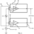
- FIG. 1 shows the basic active electrode system.
- a reference active electrode 10 comprises an amplifier 12. Contact is made with the patient at a first contact 20 which provides an input to the system.
- a first signal active electrode 16 comprises an amplifier 18. Contact is made with the patient at a second contact 22. The gain of the reference active electrode amplifier is shown as A and the gain of the signal active electrode amplifier is shown as A+ ⁇ A. Thus, there is a gain mismatch between the active electrodes.
- analogue to digital converter units may be implemented as part of the electrodes 10,16 or they may be implemented downstream from the electrodes.
- Common mode interference is one of the major problems in such active electrode biopotential signal acquisition systems.
- biopotential signals can be affected by interference currents derived from the mains power supply lines, known as "common mode aggressors".
- the mains frequency generally falls within the frequency range of interest of biomedical signals, which makes such common mode signals a particular problem.
- an ECG signal has its main frequency components in the range 0.5Hz to 40Hz, but signal information up to around 100Hz or even 200Hz is desired.
- the interference signals can have larger amplitudes than the biopotential signals to be measured.
- CMRR common mode rejection ratio
- notch filtering is normally required to remove the common mode interfering signal.
- a particular problem is that the common mode interference at the inputs of the active electrodes can be converted to a differential mode error at the outputs of active electrode pairs due to the voltage gain mismatch between the active electrode pairs, as well as the contact-impedance mismatch.
- the output error can have significant amplitude when compared to the amplitude of the biopotential signals.
- the CMRR of active electrode systems is usually limited by this voltage gain mismatch (VCM * ⁇ A) between the signal active electrode and the reference active electrode, which in return is due to the process variation and component mismatch.
- VCM * ⁇ A voltage gain mismatch
- the process variation and component mismatch make it difficult to achieve well-matched voltage gain. Without compensation circuits or trimming, achieving more than 60dB CMRR is very difficult because of the component mismatch, while medical grade biopotential systems typically require more than 80dB CMRR.
- a large common mode input interference may also saturate the active electrode, especially when the amplifier has a large voltage gain, and the other input is connected to a reference voltage. To avoid saturation of the active electrode, its voltage gain is usually limited to accommodate large input common mode dynamic range.
- WO 2014/043739 A1 Another known system for the measurement of physiological signals using active electrodes is described in WO 2014/043739 A1 , which includes a sensing element for sensing a biological signal generated in a subject's body, the biological signal including a noise component and an information carrying component: a filter module separates the noise component and the information carrying component of the biological signal from each other, the filter module generating a filtered signal from the biological signal input into the filter module; an amplifier has an inverting input and a non-inverting input, the filter module being connected to one of the inputs of the amplifier for receiving the filtered signal and the sensed biological signal being input to the other of the inputs so at least the noise component of the biological signal is attenuated relative to the information carrying component.
- biopotential signal acquisition system as in claim 1.
- the integrated amplifier of each active electrode (which functions as a pre-amplifier, as there will generally be further amplification in the signal processing path) is connected to a feedforward common mode voltage provided by the unity gain voltage buffer.
- This buffered signal is approximately equal to the input common mode signal, which can be used to bias the other input of the amplifier.
- the effective common-mode input voltage which appears at the input of each amplifier is significantly reduced. This reduces the common-mode gain of the two active electrodes, and thus improves their common mode rejection ratio. It also avoids the saturation of the active electrodes, but without affecting the differential amplification of the signal of interest.
- the system may be applied to a single channel system (with two active electrodes) or to a multiple channel system (with more than two active electrodes).
- the system can be used with different types of amplifier, including inverting and non-inverting amplifiers.
- the first and second inputs are skin contact points at which electrode pads are applied to the skin of the patient being monitored. They may be wet (gel) or dry contacts, although as described above systems using dry electrode contacts are preferred by patients for reasons of ease of use.
- the unity gain buffer may be for receiving a signal from an associated input which is additional to the first and second inputs.
- the unity gain buffer may be for receiving a signal from the first or second input. In this case, no additional contact electrodes are needed to those already required for the active electrodes.
- the unity gain buffer may for example be implemented as an operational amplifier with full negative feedback, i.e. the output connected directly to the inverting input, and the input signal from the skin contact provided to the non-inverting input.
- the unity gain buffer may then also provide the buffered output to the third integrated amplifier as a reference signal.
- the unity gain buffer may be shared between two or more active electrodes. There may be one unity gain buffer even for many active electrodes, but equally, there may be more than one unity gain buffer, each providing a reference signal to an associated set of active electrodes.
- the output of the unity gain buffer may be provided to the respective integrated amplifiers through decoupling capacitors. These prevent a dc signal from the unity gain buffer from saturating the active electrode amplifiers.
- the unity gain buffer output may be provided to inverting inputs of the respective integrated amplifiers through the decoupling capacitors, and the respective integrated amplifiers may then also comprise a negative feedback path. This feedback path may be used to stabilize the DC operating points of the active electrode amplifiers. This provides an implementation using inverting amplification of the input signals and decoupling of the buffer signal.
- the output of the unity gain buffer is provided to non-inverting inputs of the respective integrated amplifiers.
- the first and second inputs may then be provided to the respective integrated amplifiers through decoupling capacitors, and the respective integrated amplifiers may again comprise a negative feedback path. This provides an implementation using non-inverting amplification of the input signals, and decoupling of the input signals.
- the first active electrode may comprise a reference electrode
- the second active electrode may comprise one of a set of active electrode.
- the set may comprise only one active electrode (for a one channel implementation).
- the set may for example comprise between 8 and 32 active electrodes (for 8 to 32 channels respectively).
- the invention also provides a biopotential signal acquisition method as in claim 10.
- This method provides a common mode feedforward approach in which a common mode signal may be fed forward from a unity gain buffer, which may be external to the active electrodes, to any number of active electrodes, in order to improve the common mode rejection ratio.
- the first, second and common mode biopotential signals may each be received from a respective input or else the first and second biopotential signals may each be received from a respective input and the common mode biopotential signal comprises one of the first and second biopotential signals.
- Third or further biopotential signals may also be captured using a third or further active electrode comprising an associated integrated amplifier.
- the buffered output may also be provided to the third or further integrated amplifier as a reference common mode signal. In this way, the concept can be applied to single channel or multiple channel systems.
- the buffered common mode biopotential signal or the first and second biopotential signals may be provided to the respective integrated amplifiers through decoupling capacitors to suppress DC signals between the inputs.
- a negative feedback path may be used to stabilize the operating points of the amplifiers.
- the invention provides a biopotential signal acquisition system, comprising at least two active electrodes each for receiving a signal from a respective input.
- the input may for example be a dry electrode applied to the skin of a patient being monitored.
- a unity gain buffer is used to feed forward a signal from an associated input.
- the buffered output is provided to the amplifiers of the active electrodes as a reference signal.
- the buffered signal is approximately equal to the input common mode signal so that the effective common mode input voltage appearing at the inputs of each amplifier is significantly reduced. This reduces the common mode gain of the active electrodes and thus improves their common mode rejection ratio while also avoiding saturation of the active electrodes.
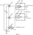
- FIG. 2 shows a first example of signal acquisition system of the invention.
- the same reference numbers are used as in Figure 1 for the same components.
- a third electrode 30 and a unity gain voltage buffer 32 generate a feedforward voltage (VCMFF in Figure 2 ) approximately equal to the input CM signal (Vcm), which can be used to bias one input of the active electrode amplifiers 12,18.
- VCMFF feedforward voltage
- the signal levels are shown in Figure 2 . These examples of signal levels are based on the common mode feedforward signal being applied to the inverting input of the amplifiers.
- the input signals are Vcm+ExG to the non-inverting input, and ⁇ Vcm to the inverting input.
- the output is (A ⁇ A)(Vcm+ExG- ⁇ Vcm).
- the output signal resulting from the common mode interference is thus (A ⁇ A)(1 - ⁇ )Vcm.
- the signal levels shown are based on input signals Vcm to the non-inverting input, and ⁇ Vcm to the inverting input.
- the output is (A)(Vcm - ⁇ Vcm).
- the output signal all results from the common mode interference because this is the reference electrode, and the output resulting from the common mode interference is thus A(1 - ⁇ )Vcm.
- the common mode feedforward signal may instead be applied to the non-inverting input of the amplifiers, and the input signals applied to the inverting inputs.
- the final differential output signal remains the same.
- the gain of the differential amplifier to the common mode input is reduced by a factor of 1/(1- ⁇ ). As ⁇ approaches 1, this reduction in gain approaches infinity, corresponding to an infinite common mode rejection ratio.
- the large common mode signal is compensated at the inputs of each amplifier, and this means that amplifier saturation is avoided.
- FIG 2 shows a system which has an input in the form of a skin contact 30 dedicated to the common mode buffer 32.
- the feedforward signal may be derived from one of the active electrode skin contacts, as shown in Figure 3 .
- the contact 20 for the reference electrode is used to derive the common mode feedforward signal.
- Figures 2 and 3 show single channel systems, with a reference active electrode and a single further active electrode. The approach can be extended to any number of active electrodes.
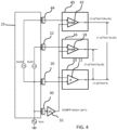
- Figure 4 shows the system extended with a third active electrode 40 with it associated amplifier 42. It receives a signal from a third input, again in the form of a patient contact 44.
- This is a two channel system, and the two biopotential signals being monitored are shown as ExG1 and ExG2.
- the common mode feedforward signal is applied to the inverting input of the amplifier of each of the three active electrodes. Both channels experience the same common mode rejection ratio if the value of ⁇ A is the same.
- the output signals resulting from the common mode interference will differ accordingly in dependence on the mismatch between the gain of the amplifier in the reference electrode 10 and in the signal electrodes 16, 42.
- Figures 1 to 4 shows the signal levels at different points in the circuit which result from the common mode interfering signal Vcm. For simplicity, the signal of interest is not shown. In each case, it comprises an additional signal (A ⁇ A)ExG at the output of the active signal electrode (or (A ⁇ A)ExG1 and (A ⁇ A)ExG2 for the two active signal electrodes in Figure 4 ).
- Figure 6 shows an example modification to the circuit of Figure 2 in which the output from the buffer 32 is supplied to the inverting inputs of the amplifiers 12,18 through respective DC blocking capacitors 60,62.
- FIG. 6 shows different DC voltage levels Vdc1, Vdc2 at the patient contacts 20, 22 relative to the common mode voltage Vcm.
- any DC voltage offset is cancelled so that only the AC components are coupled to the amplifier (such as 50 or 60Hz mains interference).
- the DC operating point after the capacitor 60, 62 is defined by a negative feedback loop 64, 66 together with capacitor 60, 62.
- This feedback loop with capacitor 60, 62 behaves as a low-pass filter, which only feeds back the DC and low frequency components to the inverting input of the amplifier. As a result, the DC voltage of the amplifier inverting input always follows its positive input. The electrode offset between leads is in this way blocked.
- the DC voltage level at both inputs of the amplifier 12 is thus Vdc1 and the DC voltage level at both inputs of the amplifier 18 is Vdc2.
- the output signals resulting from the common mode interferer are the same as in Figure 2 .
- the blocking capacitors 60,62 behave as a short circuit for the common mode signal. As discussed above, the effective common mode swing to each amplifier is reduced, which leads to improved CMRR of both active electrodes and avoid amplifier saturation.
- Figure 7 shows an implementation in which the input signals are provided to the inverting inputs of the integrated amplifiers through the decoupling capacitors 60, 62, and the buffered common mode signal is provided to the non-inverting inputs.
- the same reference numbers are used as in Figure 6 .
- the feedback paths are shown as implemented by capacitors 64, 66. Note that the common mode voltage across the input decoupling capacitors is almost zero so that there is no input common mode current. Thus, the common mode gain is reduced and the common mode rejection ratio is boosted.
- the fed forward common mode signal will be connected to each active electrode through a cable which may be long.
- the buffered output is a low impedance node, which reduces the noise and interference pick-up from environment by the cable.
- the system has better stability and faster settling time because of the elimination of the feedback loop.
- There is also improved power/bandwidth tradeoff as it is possible to use a low power analog buffer to achieve sufficient CMRR bandwidth (0.5-100Hz).
- the feedback amplifier suffers from the tradeoff between bandwidth, power and stability. The power consumption of the feedback amplifier is usually high.
- the common mode feedforward approach has been verified by hardware measurement of a 4-channel digital active electrode system for EEG recording, and shows more than 30dB CMRR improvement and significant 50/60Hz interference reduction.
- the invention is applicable generally to single or multi-channel ExG systems, especially for (digital) active electrode systems for healthcare monitoring.
- the invention does not require any particular active electrode design and can be applied regardless of the detailed architecture and implementation of the active electrodes.
Landscapes
- Life Sciences & Earth Sciences (AREA)
- Health & Medical Sciences (AREA)
- Medical Informatics (AREA)
- Biophysics (AREA)
- Pathology (AREA)
- Engineering & Computer Science (AREA)
- Biomedical Technology (AREA)
- Heart & Thoracic Surgery (AREA)
- Physics & Mathematics (AREA)
- Molecular Biology (AREA)
- Surgery (AREA)
- Animal Behavior & Ethology (AREA)
- General Health & Medical Sciences (AREA)
- Public Health (AREA)
- Veterinary Medicine (AREA)
- Measurement And Recording Of Electrical Phenomena And Electrical Characteristics Of The Living Body (AREA)
Claims (12)
- Biopotenzialsignalerfassungssystem zur Messung von Biopotentialsignalen (ExG), die von einem Patienten erzeugt werden, umfassend:eine erste aktive Elektrode (10), die einen ersten integrierten Verstärker (12) umfasst; wobei der erste integrierte Verstärker (12) einen ersten Eingang und einen ersten gepufferten Signaleingang umfasst, wobei der erste Eingang mit einem ersten Kontakt (20) verbunden ist;eine zweite aktive Elektrode (16), die einen zweiten integrierten Verstärker (18) umfasst; wobei der zweite integrierte Verstärker (18) einen zweiten Eingang und einen zweiten gepufferten Signaleingang umfasst, wobei der zweite Eingang mit einem zweiten Kontakt (22) verbunden ist; undeinen Puffer (32) mit Verstärkungsfaktor Eins, der einen Eingang, der mit dem ersten, dem zweiten oder einem dritten Kontakt (20, 22, 30) verbunden ist, und einen Ausgang aufweist, der mit dem ersten gepufferten Signaleingang des ersten integrierten Verstärkers (12) und mit dem zweiten gepufferten Signaleingang des zweiten integrierten Verstärkers (18) verbunden ist; und dadurch gekennzeichnet, dass das Biopotenzialsignalerfassungssystem so konfiguriert ist, dass, wenn die Kontakte an die Haut des Patienten angelegt werden, der erste und der zweite gepufferte Signaleingang, die von dem ersten und dem zweiten integrierten Verstärker (12, 18) empfangen werden, ein von dem Patienten erzeugtes Biopotentialsignal (ExG) enthalten.
- System nach Anspruch 1, wobei der erste gepufferte Signaleingang des ersten integrierten Verstärkers (12) und der zweite gepufferte Signaleingang des zweiten integrierten Verstärkers (18) entweder beide invertierende oder nicht-invertierende Eingänge der Verstärker sind.
- System nach einem vorstehenden Anspruch, das weiter mindestens eine dritte aktive Elektrode (40) umfasst und einen dritten integrierten Verstärker (42) umfasst.
- System nach Anspruch 3, wobei der Puffer (32) mit Verstärkungsfaktor Eins den gepufferten Ausgang an den dritten integrierten Verstärker (42) als ein Referenz-Gleichtakt-Biopotentialsignal bereitstellt.
- System nach einem vorstehenden Anspruch, wobei das gepufferte Gleichtakt-Biopotentialsignal den invertierenden Eingängen der jeweiligen integrierten Verstärker (12, 18) über Entkopplungskondensatoren (60, 62) bereitgestellt wird, und wobei die jeweiligen integrierten Verstärker (12, 18) einen negativen Rückkopplungspfad (64, 66) umfassen.
- System nach einem der Ansprüche 1 bis 4, wobei das gepufferte Gleichtakt-Biopotentialsignal nicht-invertierenden Eingängen der jeweiligen integrierten Verstärker (12, 18) bereitgestellt wird, wobei die ersten und zweiten Eingänge den jeweiligen integrierten Verstärkern (12, 18) über Entkopplungskondensatoren (60, 62) bereitgestellt werden, und wobei die jeweiligen integrierten Verstärker (12, 18) einen negativen Rückkopplungspfad (64, 66) umfassen.
- System nach einem vorstehenden Anspruch, wobei die erste aktive Elektrode (10) eine Referenzelektrode umfasst und die zweite aktive Elektrode (16) eine aus einem Satz von aktiven Elektroden umfasst.
- System nach Anspruch 7, wobei der Satz zwischen 8 und 32 aktive Elektroden umfasst.
- Elektronische Schaltung oder Vorrichtung umfassend ein Biopotenzialsignalerfassungssystem nach einem der Ansprüche 1 bis 8.
- Biopotenzialsignalerfassungsverfahren zur Messung von Biopotentialsignalen (ExG), die von einem Patienten erzeugt werden, unter Verwendung eines Systems nach Anspruch 1, umfassend:Erfassen eines ersten Biopotentialsignals unter Verwendung einer ersten aktiven Elektrode (10), die einen ersten integrierten Verstärker (12) umfasst;Erfassen eines zweiten Biopotentialsignals unter Verwendung einer zweiten aktiven Elektrode (16), die einen zweiten integrierten Verstärker (18) umfasst;Puffern eines Gleichtakt-Biopotentialsignals unter Verwendung eines Puffers (32) mit Verstärkungsfaktor Eins und dadurch gekennzeichnet, dass das gepufferte Gleichtakt-Biopotentialsignal, das auch ein vom Patienten erzeugtes Biopotentialsignal (ExG) enthält, an einen Eingang des ersten und des zweiten integrierten Verstärkers (12, 18) als ein Referenz-Gleichtaktsignal bereitgestellt wird und die integrierten Verstärker es empfangen.
- Verfahren nach Anspruch 10, weiter umfassend das Erfassen eines dritten Biopotentialsignals unter Verwendung einer dritten aktiven Elektrode (40), die einen dritten integrierten Verstärker (42) umfasst, und das Bereitstellen des gepufferten Gleichtakt-Biopotentialsignals an den dritten integrierten Verstärker (42) als ein Referenz-Gleichtaktsignal.
- Verfahren nach Anspruch 10 oder 11, umfassend das Bereitstellen des gepufferten Gleichtakt-Biopotentialsignals oder des ersten und zweiten Biopotentialsignals an die jeweiligen integrierten Verstärker (23, 18) über Entkopplungskondensatoren (60, 62) und das Bereitstellen der jeweiligen integrierten Verstärker (12, 18) mit einem negativen Rückkopplungspfad.
Priority Applications (1)
| Application Number | Priority Date | Filing Date | Title |
|---|---|---|---|
| EP15150843.9A EP3042607B1 (de) | 2015-01-12 | 2015-01-12 | Biopotenzialsignalerfassungssystem und -verfahren |
Applications Claiming Priority (1)
| Application Number | Priority Date | Filing Date | Title |
|---|---|---|---|
| EP15150843.9A EP3042607B1 (de) | 2015-01-12 | 2015-01-12 | Biopotenzialsignalerfassungssystem und -verfahren |
Publications (2)
| Publication Number | Publication Date |
|---|---|
| EP3042607A1 EP3042607A1 (de) | 2016-07-13 |
| EP3042607B1 true EP3042607B1 (de) | 2024-09-04 |
Family
ID=52292815
Family Applications (1)
| Application Number | Title | Priority Date | Filing Date |
|---|---|---|---|
| EP15150843.9A Active EP3042607B1 (de) | 2015-01-12 | 2015-01-12 | Biopotenzialsignalerfassungssystem und -verfahren |
Country Status (1)
| Country | Link |
|---|---|
| EP (1) | EP3042607B1 (de) |
Families Citing this family (2)
| Publication number | Priority date | Publication date | Assignee | Title |
|---|---|---|---|---|
| CN109199370B (zh) * | 2018-09-21 | 2021-08-13 | 北京机械设备研究所 | 一种脑电信号放大装置及方法 |
| CN113876336B (zh) * | 2021-09-02 | 2022-07-05 | 中国科学院深圳先进技术研究院 | 肌电采集参考电极的动态切换装置以及动态切换方法 |
Family Cites Families (4)
| Publication number | Priority date | Publication date | Assignee | Title |
|---|---|---|---|---|
| US3885552A (en) * | 1972-11-16 | 1975-05-27 | Pacemaker Diagnostic Clinic Of | Cardiac function monitoring system and method for use in association with cardiac pacer apparatus |
| US5813993A (en) * | 1996-04-05 | 1998-09-29 | Consolidated Research Of Richmond, Inc. | Alertness and drowsiness detection and tracking system |
| EP2442443B8 (de) * | 2010-10-15 | 2018-02-07 | IMEC vzw | Erfassungssystem für Mehrkanal-Biopotenzsignal |
| WO2014043739A1 (en) * | 2012-09-19 | 2014-03-27 | Heard Systems Pty Ltd | A system for measuring physiological signals |
-
2015
- 2015-01-12 EP EP15150843.9A patent/EP3042607B1/de active Active
Also Published As
| Publication number | Publication date |
|---|---|
| EP3042607A1 (de) | 2016-07-13 |
Similar Documents
| Publication | Publication Date | Title |
|---|---|---|
| US9681844B2 (en) | Biopotential signal acquisition system and method | |
| JP6713482B2 (ja) | アクティブ電極,センサ・システム,および電位差検出方法 | |
| EP2442443B1 (de) | Erfassungssystem für Mehrkanal-Biopotenzsignal | |
| Lee et al. | An ultra-high input impedance analog front end using self-calibrated positive feedback | |
| TWI481196B (zh) | 生物電信號感測儀器與其基線漂移移除裝置 | |
| EP2819306B1 (de) | Instrumentenverstärker und zur Signalverstärkungsverfahren. | |
| US20080159365A1 (en) | Analog Conditioning of Bioelectric Signals | |
| US9190966B2 (en) | Impedance bootstrap circuit for an interface of a monitoring device | |
| CN107979377A (zh) | 具有电容差分电路和数字σ-δ反馈的adc | |
| US11350866B2 (en) | Read-out circuitry for acquiring a multi-channel biopotential signal and a sensor for sensing a biopotential signal | |
| Dabbaghian et al. | An active electrode IC with embedded analog CMRR enhancement for interference-and gain-mismatch-resilient EEG recording | |
| EP3042607A1 (de) | Biopotenzialsignalerfassungssystem und -verfahren | |
| US20050228306A1 (en) | System and method for filtering and detecting faint signals in noise | |
| Hong et al. | A 46 μW motion artifact reduction bio-signal sensor with ICA based adaptive DC level control for sleep monitoring system | |
| WO2016035104A1 (en) | Signal acquisition system | |
| Pourahmad et al. | Two-wired current modulator active electrode for ambulatory biosignal recording | |
| US20220015712A1 (en) | Biosignal Monitoring System With Motion Artifact Reduction | |
| KR102402752B1 (ko) | 50/60Hz 잡음 억제용 무선 능동 전극 및 이에 기반한 심전도 측정 장치 | |
| Ji et al. | An active electrode design for weak biosignal measurements | |
| EP4181769B1 (de) | Vorrichtung zur messung des biopotentials | |
| US12440143B2 (en) | Signal acquisition circuit and physiological detection apparatus | |
| US10542900B2 (en) | Device and method for detecting electric potentials | |
| Thanapitak et al. | Test Bench for Biopotential Instrumentation Amplifier using Single-Ended to Differential Amplifiers | |
| Yin et al. | An Orthogonal Code-Division Multiplexing AFE with low Channel-Gain-Mismatch by Input Capacitors Calibration Technology | |
| Guimarães et al. | Analog Front-End for ECG Signal Acquisition with Automatic Gain Control |
Legal Events
| Date | Code | Title | Description |
|---|---|---|---|
| PUAI | Public reference made under article 153(3) epc to a published international application that has entered the european phase |
Free format text: ORIGINAL CODE: 0009012 |
|
| AK | Designated contracting states |
Kind code of ref document: A1 Designated state(s): AL AT BE BG CH CY CZ DE DK EE ES FI FR GB GR HR HU IE IS IT LI LT LU LV MC MK MT NL NO PL PT RO RS SE SI SK SM TR |
|
| AX | Request for extension of the european patent |
Extension state: BA ME |
|
| STAA | Information on the status of an ep patent application or granted ep patent |
Free format text: STATUS: REQUEST FOR EXAMINATION WAS MADE |
|
| 17P | Request for examination filed |
Effective date: 20170112 |
|
| RBV | Designated contracting states (corrected) |
Designated state(s): AL AT BE BG CH CY CZ DE DK EE ES FI FR GB GR HR HU IE IS IT LI LT LU LV MC MK MT NL NO PL PT RO RS SE SI SK SM TR |
|
| STAA | Information on the status of an ep patent application or granted ep patent |
Free format text: STATUS: EXAMINATION IS IN PROGRESS |
|
| 17Q | First examination report despatched |
Effective date: 20180206 |
|
| REG | Reference to a national code |
Ref country code: DE Ref legal event code: R079 Free format text: PREVIOUS MAIN CLASS: A61B0005040000 Ipc: A61B0005300000 Ref country code: DE Ref legal event code: R079 Ref document number: 602015089747 Country of ref document: DE Free format text: PREVIOUS MAIN CLASS: A61B0005040000 Ipc: A61B0005300000 |
|
| RIC1 | Information provided on ipc code assigned before grant |
Ipc: A61B 5/30 20210101AFI20231114BHEP |
|
| GRAP | Despatch of communication of intention to grant a patent |
Free format text: ORIGINAL CODE: EPIDOSNIGR1 |
|
| STAA | Information on the status of an ep patent application or granted ep patent |
Free format text: STATUS: GRANT OF PATENT IS INTENDED |
|
| INTG | Intention to grant announced |
Effective date: 20240326 |
|
| P01 | Opt-out of the competence of the unified patent court (upc) registered |
Effective date: 20240523 |
|
| GRAS | Grant fee paid |
Free format text: ORIGINAL CODE: EPIDOSNIGR3 |
|
| GRAA | (expected) grant |
Free format text: ORIGINAL CODE: 0009210 |
|
| STAA | Information on the status of an ep patent application or granted ep patent |
Free format text: STATUS: THE PATENT HAS BEEN GRANTED |
|
| AK | Designated contracting states |
Kind code of ref document: B1 Designated state(s): AL AT BE BG CH CY CZ DE DK EE ES FI FR GB GR HR HU IE IS IT LI LT LU LV MC MK MT NL NO PL PT RO RS SE SI SK SM TR |
|
| REG | Reference to a national code |
Ref country code: GB Ref legal event code: FG4D |
|
| REG | Reference to a national code |
Ref country code: CH Ref legal event code: EP |
|
| REG | Reference to a national code |
Ref country code: IE Ref legal event code: FG4D |
|
| REG | Reference to a national code |
Ref country code: DE Ref legal event code: R096 Ref document number: 602015089747 Country of ref document: DE |
|
| REG | Reference to a national code |
Ref country code: LT Ref legal event code: MG9D |
|
| REG | Reference to a national code |
Ref country code: NL Ref legal event code: MP Effective date: 20240904 |
|
| PG25 | Lapsed in a contracting state [announced via postgrant information from national office to epo] |
Ref country code: NO Free format text: LAPSE BECAUSE OF FAILURE TO SUBMIT A TRANSLATION OF THE DESCRIPTION OR TO PAY THE FEE WITHIN THE PRESCRIBED TIME-LIMIT Effective date: 20241204 |
|
| PG25 | Lapsed in a contracting state [announced via postgrant information from national office to epo] |
Ref country code: PL Free format text: LAPSE BECAUSE OF FAILURE TO SUBMIT A TRANSLATION OF THE DESCRIPTION OR TO PAY THE FEE WITHIN THE PRESCRIBED TIME-LIMIT Effective date: 20240904 Ref country code: GR Free format text: LAPSE BECAUSE OF FAILURE TO SUBMIT A TRANSLATION OF THE DESCRIPTION OR TO PAY THE FEE WITHIN THE PRESCRIBED TIME-LIMIT Effective date: 20241205 Ref country code: FI Free format text: LAPSE BECAUSE OF FAILURE TO SUBMIT A TRANSLATION OF THE DESCRIPTION OR TO PAY THE FEE WITHIN THE PRESCRIBED TIME-LIMIT Effective date: 20240904 |
|
| PG25 | Lapsed in a contracting state [announced via postgrant information from national office to epo] |
Ref country code: BG Free format text: LAPSE BECAUSE OF FAILURE TO SUBMIT A TRANSLATION OF THE DESCRIPTION OR TO PAY THE FEE WITHIN THE PRESCRIBED TIME-LIMIT Effective date: 20240904 |
|
| PG25 | Lapsed in a contracting state [announced via postgrant information from national office to epo] |
Ref country code: LV Free format text: LAPSE BECAUSE OF FAILURE TO SUBMIT A TRANSLATION OF THE DESCRIPTION OR TO PAY THE FEE WITHIN THE PRESCRIBED TIME-LIMIT Effective date: 20240904 |
|
| PG25 | Lapsed in a contracting state [announced via postgrant information from national office to epo] |
Ref country code: HR Free format text: LAPSE BECAUSE OF FAILURE TO SUBMIT A TRANSLATION OF THE DESCRIPTION OR TO PAY THE FEE WITHIN THE PRESCRIBED TIME-LIMIT Effective date: 20240904 |
|
| PG25 | Lapsed in a contracting state [announced via postgrant information from national office to epo] |
Ref country code: ES Free format text: LAPSE BECAUSE OF FAILURE TO SUBMIT A TRANSLATION OF THE DESCRIPTION OR TO PAY THE FEE WITHIN THE PRESCRIBED TIME-LIMIT Effective date: 20240904 Ref country code: RS Free format text: LAPSE BECAUSE OF FAILURE TO SUBMIT A TRANSLATION OF THE DESCRIPTION OR TO PAY THE FEE WITHIN THE PRESCRIBED TIME-LIMIT Effective date: 20241204 |
|
| PG25 | Lapsed in a contracting state [announced via postgrant information from national office to epo] |
Ref country code: RS Free format text: LAPSE BECAUSE OF FAILURE TO SUBMIT A TRANSLATION OF THE DESCRIPTION OR TO PAY THE FEE WITHIN THE PRESCRIBED TIME-LIMIT Effective date: 20241204 Ref country code: PL Free format text: LAPSE BECAUSE OF FAILURE TO SUBMIT A TRANSLATION OF THE DESCRIPTION OR TO PAY THE FEE WITHIN THE PRESCRIBED TIME-LIMIT Effective date: 20240904 Ref country code: NO Free format text: LAPSE BECAUSE OF FAILURE TO SUBMIT A TRANSLATION OF THE DESCRIPTION OR TO PAY THE FEE WITHIN THE PRESCRIBED TIME-LIMIT Effective date: 20241204 Ref country code: LV Free format text: LAPSE BECAUSE OF FAILURE TO SUBMIT A TRANSLATION OF THE DESCRIPTION OR TO PAY THE FEE WITHIN THE PRESCRIBED TIME-LIMIT Effective date: 20240904 Ref country code: HR Free format text: LAPSE BECAUSE OF FAILURE TO SUBMIT A TRANSLATION OF THE DESCRIPTION OR TO PAY THE FEE WITHIN THE PRESCRIBED TIME-LIMIT Effective date: 20240904 Ref country code: GR Free format text: LAPSE BECAUSE OF FAILURE TO SUBMIT A TRANSLATION OF THE DESCRIPTION OR TO PAY THE FEE WITHIN THE PRESCRIBED TIME-LIMIT Effective date: 20241205 Ref country code: FI Free format text: LAPSE BECAUSE OF FAILURE TO SUBMIT A TRANSLATION OF THE DESCRIPTION OR TO PAY THE FEE WITHIN THE PRESCRIBED TIME-LIMIT Effective date: 20240904 Ref country code: ES Free format text: LAPSE BECAUSE OF FAILURE TO SUBMIT A TRANSLATION OF THE DESCRIPTION OR TO PAY THE FEE WITHIN THE PRESCRIBED TIME-LIMIT Effective date: 20240904 Ref country code: BG Free format text: LAPSE BECAUSE OF FAILURE TO SUBMIT A TRANSLATION OF THE DESCRIPTION OR TO PAY THE FEE WITHIN THE PRESCRIBED TIME-LIMIT Effective date: 20240904 |
|
| REG | Reference to a national code |
Ref country code: AT Ref legal event code: MK05 Ref document number: 1719521 Country of ref document: AT Kind code of ref document: T Effective date: 20240904 |
|
| PG25 | Lapsed in a contracting state [announced via postgrant information from national office to epo] |
Ref country code: NL Free format text: LAPSE BECAUSE OF FAILURE TO SUBMIT A TRANSLATION OF THE DESCRIPTION OR TO PAY THE FEE WITHIN THE PRESCRIBED TIME-LIMIT Effective date: 20240904 |
|
| PG25 | Lapsed in a contracting state [announced via postgrant information from national office to epo] |
Ref country code: PT Free format text: LAPSE BECAUSE OF FAILURE TO SUBMIT A TRANSLATION OF THE DESCRIPTION OR TO PAY THE FEE WITHIN THE PRESCRIBED TIME-LIMIT Effective date: 20250106 Ref country code: IS Free format text: LAPSE BECAUSE OF FAILURE TO SUBMIT A TRANSLATION OF THE DESCRIPTION OR TO PAY THE FEE WITHIN THE PRESCRIBED TIME-LIMIT Effective date: 20250104 |
|
| PG25 | Lapsed in a contracting state [announced via postgrant information from national office to epo] |
Ref country code: SM Free format text: LAPSE BECAUSE OF FAILURE TO SUBMIT A TRANSLATION OF THE DESCRIPTION OR TO PAY THE FEE WITHIN THE PRESCRIBED TIME-LIMIT Effective date: 20240904 Ref country code: RO Free format text: LAPSE BECAUSE OF FAILURE TO SUBMIT A TRANSLATION OF THE DESCRIPTION OR TO PAY THE FEE WITHIN THE PRESCRIBED TIME-LIMIT Effective date: 20240904 |
|
| PG25 | Lapsed in a contracting state [announced via postgrant information from national office to epo] |
Ref country code: EE Free format text: LAPSE BECAUSE OF FAILURE TO SUBMIT A TRANSLATION OF THE DESCRIPTION OR TO PAY THE FEE WITHIN THE PRESCRIBED TIME-LIMIT Effective date: 20240904 Ref country code: AT Free format text: LAPSE BECAUSE OF FAILURE TO SUBMIT A TRANSLATION OF THE DESCRIPTION OR TO PAY THE FEE WITHIN THE PRESCRIBED TIME-LIMIT Effective date: 20240904 |
|
| PG25 | Lapsed in a contracting state [announced via postgrant information from national office to epo] |
Ref country code: CZ Free format text: LAPSE BECAUSE OF FAILURE TO SUBMIT A TRANSLATION OF THE DESCRIPTION OR TO PAY THE FEE WITHIN THE PRESCRIBED TIME-LIMIT Effective date: 20240904 |
|
| PG25 | Lapsed in a contracting state [announced via postgrant information from national office to epo] |
Ref country code: IT Free format text: LAPSE BECAUSE OF FAILURE TO SUBMIT A TRANSLATION OF THE DESCRIPTION OR TO PAY THE FEE WITHIN THE PRESCRIBED TIME-LIMIT Effective date: 20240904 Ref country code: SK Free format text: LAPSE BECAUSE OF FAILURE TO SUBMIT A TRANSLATION OF THE DESCRIPTION OR TO PAY THE FEE WITHIN THE PRESCRIBED TIME-LIMIT Effective date: 20240904 |
|
| REG | Reference to a national code |
Ref country code: DE Ref legal event code: R097 Ref document number: 602015089747 Country of ref document: DE |
|
| PG25 | Lapsed in a contracting state [announced via postgrant information from national office to epo] |
Ref country code: DK Free format text: LAPSE BECAUSE OF FAILURE TO SUBMIT A TRANSLATION OF THE DESCRIPTION OR TO PAY THE FEE WITHIN THE PRESCRIBED TIME-LIMIT Effective date: 20240904 |
|
| PLBE | No opposition filed within time limit |
Free format text: ORIGINAL CODE: 0009261 |
|
| STAA | Information on the status of an ep patent application or granted ep patent |
Free format text: STATUS: NO OPPOSITION FILED WITHIN TIME LIMIT |
|
| 26N | No opposition filed |
Effective date: 20250605 |
|
| REG | Reference to a national code |
Ref country code: CH Ref legal event code: PL |
|
| PG25 | Lapsed in a contracting state [announced via postgrant information from national office to epo] |
Ref country code: SE Free format text: LAPSE BECAUSE OF FAILURE TO SUBMIT A TRANSLATION OF THE DESCRIPTION OR TO PAY THE FEE WITHIN THE PRESCRIBED TIME-LIMIT Effective date: 20240904 |
|
| PG25 | Lapsed in a contracting state [announced via postgrant information from national office to epo] |
Ref country code: LU Free format text: LAPSE BECAUSE OF NON-PAYMENT OF DUE FEES Effective date: 20250112 Ref country code: MC Free format text: LAPSE BECAUSE OF FAILURE TO SUBMIT A TRANSLATION OF THE DESCRIPTION OR TO PAY THE FEE WITHIN THE PRESCRIBED TIME-LIMIT Effective date: 20240904 |
|
| GBPC | Gb: european patent ceased through non-payment of renewal fee |
Effective date: 20250112 |
|
| PG25 | Lapsed in a contracting state [announced via postgrant information from national office to epo] |
Ref country code: BE Free format text: LAPSE BECAUSE OF NON-PAYMENT OF DUE FEES Effective date: 20250131 Ref country code: GB Free format text: LAPSE BECAUSE OF NON-PAYMENT OF DUE FEES Effective date: 20250112 |
|
| PG25 | Lapsed in a contracting state [announced via postgrant information from national office to epo] |
Ref country code: FR Free format text: LAPSE BECAUSE OF NON-PAYMENT OF DUE FEES Effective date: 20250131 |
|
| PG25 | Lapsed in a contracting state [announced via postgrant information from national office to epo] |
Ref country code: CH Free format text: LAPSE BECAUSE OF NON-PAYMENT OF DUE FEES Effective date: 20250131 |
|
| REG | Reference to a national code |
Ref country code: BE Ref legal event code: MM Effective date: 20250131 |
|
| PG25 | Lapsed in a contracting state [announced via postgrant information from national office to epo] |
Ref country code: IE Free format text: LAPSE BECAUSE OF NON-PAYMENT OF DUE FEES Effective date: 20250112 |
|
| PGFP | Annual fee paid to national office [announced via postgrant information from national office to epo] |
Ref country code: DE Payment date: 20251217 Year of fee payment: 12 |