EP3043017B2 - Drainagesystem für tür- und fensterelemente - Google Patents
Drainagesystem für tür- und fensterelemente Download PDFInfo
- Publication number
- EP3043017B2 EP3043017B2 EP15202343.8A EP15202343A EP3043017B2 EP 3043017 B2 EP3043017 B2 EP 3043017B2 EP 15202343 A EP15202343 A EP 15202343A EP 3043017 B2 EP3043017 B2 EP 3043017B2
- Authority
- EP
- European Patent Office
- Prior art keywords
- drainage
- drainage channel
- profile
- drainage system
- channel
- Prior art date
- Legal status (The legal status is an assumption and is not a legal conclusion. Google has not performed a legal analysis and makes no representation as to the accuracy of the status listed.)
- Active
Links
Images




Classifications
-
- E—FIXED CONSTRUCTIONS
- E06—DOORS, WINDOWS, SHUTTERS, OR ROLLER BLINDS IN GENERAL; LADDERS
- E06B—FIXED OR MOVABLE CLOSURES FOR OPENINGS IN BUILDINGS, VEHICLES, FENCES OR LIKE ENCLOSURES IN GENERAL, e.g. DOORS, WINDOWS, BLINDS, GATES
- E06B7/00—Special arrangements or measures in connection with doors or windows
- E06B7/14—Measures for draining-off condensed water or water leaking-in frame members for draining off condensation water, throats at the bottom of a sash
-
- E—FIXED CONSTRUCTIONS
- E06—DOORS, WINDOWS, SHUTTERS, OR ROLLER BLINDS IN GENERAL; LADDERS
- E06B—FIXED OR MOVABLE CLOSURES FOR OPENINGS IN BUILDINGS, VEHICLES, FENCES OR LIKE ENCLOSURES IN GENERAL, e.g. DOORS, WINDOWS, BLINDS, GATES
- E06B1/00—Border constructions of openings in walls, floors, or ceilings; Frames to be rigidly mounted in such openings
- E06B1/62—Tightening or covering joints between the border of openings and the frame or between contiguous frames
- E06B1/68—Tightening or covering joints between the border of openings and the frame or between contiguous frames by profiled external parts
-
- E—FIXED CONSTRUCTIONS
- E06—DOORS, WINDOWS, SHUTTERS, OR ROLLER BLINDS IN GENERAL; LADDERS
- E06B—FIXED OR MOVABLE CLOSURES FOR OPENINGS IN BUILDINGS, VEHICLES, FENCES OR LIKE ENCLOSURES IN GENERAL, e.g. DOORS, WINDOWS, BLINDS, GATES
- E06B1/00—Border constructions of openings in walls, floors, or ceilings; Frames to be rigidly mounted in such openings
- E06B1/70—Sills; Thresholds
- E06B2001/707—Thresholds with special provision for insulation
-
- E—FIXED CONSTRUCTIONS
- E06—DOORS, WINDOWS, SHUTTERS, OR ROLLER BLINDS IN GENERAL; LADDERS
- E06B—FIXED OR MOVABLE CLOSURES FOR OPENINGS IN BUILDINGS, VEHICLES, FENCES OR LIKE ENCLOSURES IN GENERAL, e.g. DOORS, WINDOWS, BLINDS, GATES
- E06B7/00—Special arrangements or measures in connection with doors or windows
- E06B7/26—Rain or draught deflectors, e.g. under sliding wings also protection against light for doors
Definitions
- the invention relates to a drainage system for draining surface water in the threshold area of door or window elements with a drainage channel and at least one drain that can be connected to a ground-based drainage system.
- Linear surface drainage systems are known in practice in many different designs. They are particularly important when large flat areas with no (or too little) slope direct the surface water that collects during rain towards the threshold of door or window elements.
- door or window elements are mentioned below, this should also include corresponding door or window sliding systems.
- the water collected in the drainage channel is then fed into a subterranean drainage system via a drain located either on the underside or on the side.
- the DE 20 2013 003 423 U1 discloses a drainage system with a threshold for barrier-free transitions.
- the threshold consists of the end bodies and the support body arranged between them. These three elements, together with the magnetic strips, form the entire surface of the threshold of the door or window element.
- a drainage system which includes a sill profile.
- This sill profile is made up of the interior profile and the exterior profile.
- a drainage channel in the form of the channel profile is connected to the sill profile.
- the DE 299 05 191 U1 concerns a base connection element which is attached to building walls - sometimes with a Fig. 3 door or window element shown - and forms a permanent base connection and drainage closure.
- a drainage system for connection to a patio window D is shown.
- a grating support frame is connected to the lower frame of the window via the connection points. This grating support frame also represents the drainage channel via its internal cavity.
- the RAL Installation guidelines according to the RAL Quality Association provide for the use of drainage channels (drainage) as a supporting structural measure.
- drainage channels drainage
- two different trades namely door and window installation on the one hand and paving work on the other, have to be coordinated with one another.
- the drainage system is either positioned in such a way that effective surface drainage directly in front of the door or window is not guaranteed, or it is not sufficiently taken into account during the planning stage.
- the present invention is based on the object of designing the drainage system mentioned at the beginning and described in more detail above in such a way that the threshold and drainage channel are coordinated with one another in such a way that both elements can be connected to one another and that it can also be used for all types of barrier-free threshold situations.
- the threshold and drainage system enables optimal adaptation and integrates the drainage channel directly into the threshold area of the door, window or sliding system.
- the base profile used for this was realized using a thermally separated base profile and is designed in such a way that it accommodates the lower sealing point of the door or window, but at the same time also enables the direct connection of the linear surface drainage channel.
- the base profile and the drainage channel each have connecting elements running over their entire length for positive and/or non-positive connection to one another.
- the base profile has a, preferably spring-loaded, receptacle for a corresponding clamping bar.
- a design with a clamping bar on the base profile and a corresponding receptacle in the drainage channel is of course also conceivable.
- the base profile has a support surface to transfer the load of the drainage channel. This is particularly advantageous during the construction of the outer surface after the drainage channel has been installed, as this means that the drainage channel can bear loads, is fully functional and can be walked on right from the start, even if the final paving has not yet been completed.
- the base profile has a receptacle for fastening a film that ensures the waterproofing of the building at the connection.
- a waterproof film such as a PVC film
- the film can preferably be attached to the receptacle of the base profile using fastening clips.
- the film then expediently runs along the support surface of the base profile and is pressed onto the base profile by the drainage channel.
- the base profile has coupling options for connecting to other profiles, webs or the like.
- the drainage system according to the invention can also be attached to existing threshold profiles and thus used for retrofitting.
- the base profile and the drainage channel are preferably made of aluminum profiles. This enables simple production, high stability and durability.
- the actual drainage channel can be flexibly adapted to the desired length, element width or reveal of the respective threshold situation.
- its length can be optimally adapted to the existing base profile by shortening it accordingly on site. This is then permanently closed using appropriate end caps.
- the drainage channel has a number of screw channels to accommodate screw connections with the end caps that can be screwed onto the open ends of the drainage channel.
- the drainage system according to the invention can be used anywhere.
- the drainage of the channel with a drainage capacity of approx. 200 l/min. can be carried out via a standard DN 50 connection, which can be freely positioned in the channel and, depending on requirements, can also be set multiple times.
- the DN standard ensures a defined interface to ground-based drainage systems.
- a further teaching of the invention provides that the drainage channel has a clamping bar or a receptacle for connecting to a connection or cover profile in the area of its side edge facing away from the threshold.
- a corresponding connection or cover profile therefore provides a corresponding receptacle or a clamping bar for connecting to the drainage channel. This achieves a particularly elegant transition to the adjacent paving surface.
- the drainage channel has a web for transferring the load to the base profile, which has a corresponding support surface.
- a stable unit of both construction elements is therefore created.
- the drainage channel has a plurality of screw channels for receiving screw connections with end caps that can be attached to the open ends of the drainage channel.
- the firm screw connection reliably guarantees that no water can escape from the sides of the drainage channel.
- the drainage channel has at least one receiving channel for support feet on its underside.
- the support feet which are preferably height-adjustable, can support point loads of up to 1.5 t.
- the support feet can also be freely positioned along the length of the drainage channel.
- the drainage system according to the invention is covered with a drainage grate.
- High-quality, salt-resistant stainless steel grates can be used for this purpose.
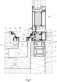
- Fig. 1 shows a first embodiment of a drainage system according to the invention, shown for the application of a door system with a door profile 1, which has a drop-down seal 2 on its underside and an externally arranged rain drainage profile 3.
- a threshold profile 4 can be seen, which in the illustrated and thus preferred embodiment is almost flush with an interior floor covering 5.
- the other structural elements shown such as foundation, insulation elements, screed, backfill tape, etc., are not provided with separate reference symbols, since these are present on site and have nothing to do directly with the drainage system according to the invention.
- a base profile 6 which is connected to the base profile 4 and rests on a support profile 8 carried by a support angle 7.
- the support profile 8 has unspecified mounting rails in its upper area, which serve to attach an inner and an outer film 9 as a moisture barrier to the support profile 8 with corresponding fastening clips.
- the actual drainage system initially and essentially comprises a drainage channel 11, which in cross-section has a connecting or covering profile 12 at its end facing away from the threshold and thus enables a stable and orderly transition to the adjacent paving P.
- a drain which initially consists of a screw socket 13, which is screwed into a socket 14, which in turn is screwed into a Angle pipe 15 is located which ends in a drain pipe 16 which leads into an underground drainage system (not shown).
- the actual connection between the base profile 6 and the drainage channel 11 is described in more detail below. It can also be seen that the drainage channel 11 is supported on the base profile 6 on the building side and is provided with a height-adjustable support foot 17 on the other side. A drainage grate 18 covers the drainage channel 11 at the top. A film 19 also ensures reliable drainage of all water, which can be pulled up on the external insulation to the base profile 6 and held there with a fastening clip 20 before the drainage channel 11 is hung in place.
- Fig. 2 describes a similar situation as in Fig. 1 , however, no door system is shown, but rather a version of a floor-to-ceiling window. Firstly, you can see a window profile 1' which is supported by a seal on a stop 2' of a threshold profile 4'. Here too, a rainwater drainage profile 3' ensures that the rainwater running down the window is directed into the drainage system.
- the threshold element 4' is firmly connected to the base profile 6 underneath via screwed or attached additional profiles (not specified in more detail). Due to the other reference symbols, reference is made to the - identical - description of Fig. 1 referred to.
- Fig. 3 shows a drainage system with a sliding system, which is not part of the invention.
- the profile 1" of the sliding element can be seen, which can be moved by means of a roller 2" on an unspecified rail of a threshold profile 4".
- the sliding element is located further inside the building and the threshold element 4" is correspondingly wider.
- a cover plate 3" ensures that the surface water is fed into the actual drainage channel 11.
- the threshold element 4" rests on two insulation elements 8' resting on the foundation and a support angle 7'. As in the previous embodiments, the edge of the inner and outer foils 9 is pulled up to the threshold element 4".
- the threshold element 4" is connected to a base element 6' underneath, which has a slightly different structure but the same function as the base profiles 6 already described in the Fig. 1 and 2 If water should enter the area directly below the cover plate, it will be drained through the horizontally permeable threshold profile 4" and over the base element 6' along the unspecified arrow in Fig. 3 also led into the drainage channel 11.
- the drainage channel 11 is identical to the drainage channels 11 already described. However, because the drainage channel 11 is installed deeper in this embodiment, the connection and cover profile 12' shown is also designed to be correspondingly higher, but fulfils the same function in relation to the paving P as already described. Fig. 1 described. The purpose of this deeper drainage channel (11) is to provide the possibility of draining the sliding element or a door or window element in a concealed manner.
- the further structure below the drainage channel 11 with the drainage elements 13, 14, 15 and 16 as well as the support foot 17 is again identical to the embodiments already described.
- a different, higher drainage grate 18' is also used, the cross-section of which is adapted to the geometric conditions.
- the film 19 is again attached to a corresponding holder of the base profile 6' using fastening clips 20.
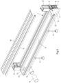
- Fig. 4 now a drainage system according to Fig. 1 shown in perspective. Firstly, one can see the threshold profile 4 and the drainage channel 11 attached to it, as well as the base profile 6 and the support profile 8. The two films 9 and the film 19 are only indicated by dash-dot lines.
- the threshold profile 4 is laterally limited by two vertically arranged frame profiles 21. End caps 22 close the open ends of the drainage channel 11 so that the water collecting therein can drain through the drain connection 13 and pipes 15 and 16, as already described. Furthermore, Fig. 4 The two support feet 17 used in this embodiment, the plug-on connection or cover profile 12 and the drainage grate 18 can also be seen.
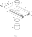
- Fig. 5 now shows a short section of a drainage channel 11 according to the invention with an unspecified hole in the bottom for receiving the screw socket 13, which can be screwed into the end socket 14 and is sealed by means of a seal 14*. Furthermore, the individually shown end cap 22 can be seen, which is provided with three unspecified holes for receiving screws 23.
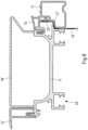
- Fig. 6 now shows the individual elements in cross-section in the not yet assembled state.
- the Fig. 6 The drainage channel 11 shown individually has, in the illustrated and thus preferred embodiment, a clamping web 24 for the positive and non-positive connection to the base profile 6. On the side facing away from the base profile 6, one can see a further clamping web 24' projecting upwards, which is connected to the connection or cover profile 12 arranged at a distance above it.
- the receiving channel 26 for receiving the support feet 17 can also be seen.
- the drainage channel 11 On the side facing the base profile 6, the drainage channel 11 also has a web 27 for transferring the load to the base profile 6.
- connection or cover profile 12 has a receptacle 28 on its underside, which corresponds to the clamping web 24' and creates a clean transition of the drainage system to the paving (not shown here).
- the base profile 6 is designed to be thermally separated to avoid a cold bridge and has, on its side facing the drainage channel 11, a receiving channel 29 for receiving the clamping web 24 of the drainage channel 11. Corresponding to the web 27 of the drainage channel 11, the base profile 6 has a shoulder 30 for supporting and thus for load transfer.
- a further receiving channel 31 serves, as already mentioned, Fig. 1 described for fastening the upper edge of a film (not shown) by means of fastening clips (also not shown).
- Fig. 7 now shows all elements from Fig. 6 and the already described foil 19 together with the fastening clip 20 in the fully assembled state. It is clearly visible that this is the same situation as in Fig. 1 and Fig. 2 is described.
- the reference symbols for the clamping bars 24' and 25' of the drainage channel 11 and the corresponding receptacles 28 and 29 have been omitted for reasons of clarity.
- the receptacle for fastening the film 19 by means of fastening clips 20 is also located in the "dry area" in the base element 6', since the projecting receptacle 29 for the clamping web 35 of the drainage channel 11 forms a water drip edge.
- connection or cover profile 12' forms a reliable hold for the adjacent leg of the attached drainage grate 18'.
Landscapes
- Engineering & Computer Science (AREA)
- Civil Engineering (AREA)
- Structural Engineering (AREA)
- Specific Sealing Or Ventilating Devices For Doors And Windows (AREA)
Priority Applications (1)
| Application Number | Priority Date | Filing Date | Title |
|---|---|---|---|
| PL15202343.8T PL3043017T5 (pl) | 2015-01-09 | 2015-12-23 | System drenażowy do elementów drzwi i okien |
Applications Claiming Priority (1)
| Application Number | Priority Date | Filing Date | Title |
|---|---|---|---|
| DE102015100266.3A DE102015100266A1 (de) | 2015-01-09 | 2015-01-09 | Drainagesystem für Tür- und Fensterelemente |
Publications (3)
| Publication Number | Publication Date |
|---|---|
| EP3043017A1 EP3043017A1 (de) | 2016-07-13 |
| EP3043017B1 EP3043017B1 (de) | 2018-11-14 |
| EP3043017B2 true EP3043017B2 (de) | 2024-10-23 |
Family
ID=55027457
Family Applications (1)
| Application Number | Title | Priority Date | Filing Date |
|---|---|---|---|
| EP15202343.8A Active EP3043017B2 (de) | 2015-01-09 | 2015-12-23 | Drainagesystem für tür- und fensterelemente |
Country Status (3)
| Country | Link |
|---|---|
| EP (1) | EP3043017B2 (pl) |
| DE (1) | DE102015100266A1 (pl) |
| PL (1) | PL3043017T5 (pl) |
Families Citing this family (6)
| Publication number | Priority date | Publication date | Assignee | Title |
|---|---|---|---|---|
| CN106837123A (zh) * | 2017-04-03 | 2017-06-13 | 张祯翔 | 一种建筑门窗迂回排水孔盖 |
| DE202018100426U1 (de) * | 2018-01-25 | 2018-02-07 | Thomas Seidl | Lastabtragendes Ausgleichselement mit Wärmedämmung |
| DE102018112434A1 (de) * | 2018-05-24 | 2019-11-28 | SCHÜCO International KG | Fenster |
| DE102019116285A1 (de) * | 2019-06-14 | 2020-12-17 | Gest Holding Gmbh | Entwässerungsvorrichtung sowie Verdunkelungssystem aufweisend die Entwässerungsvorrichtung |
| DE202019106103U1 (de) | 2019-11-04 | 2019-11-25 | Hautau Gmbh | Drainageeinrichtung für Tür- oder Fensterelemente |
| AT524419B1 (de) * | 2021-08-06 | 2022-06-15 | Mueller Guenther | Formteil |
Citations (3)
| Publication number | Priority date | Publication date | Assignee | Title |
|---|---|---|---|---|
| DE202010004020U1 (de) † | 2010-03-22 | 2011-07-27 | Inge Frey | Bodenschwelle |
| DE202013003423U1 (de) † | 2013-04-12 | 2013-05-27 | Inge Frey | Bodenschwelle , insbesondere für barrierefreie Übergänge |
| WO2013113914A2 (de) † | 2012-02-03 | 2013-08-08 | Claudia Rager-Frey | Barrierefreie bodenschwelle, insbesondere altbau- bzw. renovierungsschwelle |
Family Cites Families (10)
| Publication number | Priority date | Publication date | Assignee | Title |
|---|---|---|---|---|
| DE4433145A1 (de) | 1994-09-17 | 1996-03-21 | Harry Frey | Magnetische Türdichtung |
| DE29507277U1 (de) | 1995-05-02 | 1995-07-20 | Frey, Harry, 87600 Kaufbeuren | Bodenschwelle für Türen |
| JP3234516B2 (ja) * | 1996-08-05 | 2001-12-04 | ワイケイケイアーキテクチュラルプロダクツ株式会社 | 排水溝ユニットおよびこれを用いた建物開口部の排水構造 |
| DE19744242A1 (de) * | 1997-10-07 | 1999-04-29 | Peter Willrich | Türschwellenvorrichtung mit einer Türschwelle |
| DE29905191U1 (de) * | 1999-03-22 | 2000-08-17 | Ruch, Herwig, Dipl.-Ing.-Architekt (FH), 73540 Heubach | Sockelanschlußelement |
| DE20106929U1 (de) | 2001-04-20 | 2002-08-29 | Frey, Inge, 87600 Kaufbeuren | Türdichtung |
| DE102009056118A1 (de) | 2009-11-30 | 2011-06-01 | Inge Frey | Dichtung, insbesondere für Schiebetüren |
| BE1019134A3 (nl) * | 2010-01-07 | 2012-03-06 | Reynaers Aluminium Nv | Afwateringssysteem voor een schuifraam of schuifdeur. |
| AT511798B1 (de) * | 2011-12-29 | 2013-03-15 | Ifn Holding Ag | Bodenschwelle für eine hebe/schiebetür |
| GB201318985D0 (en) | 2013-10-28 | 2013-12-11 | Kennedy Anne | A drainage unit |
-
2015
- 2015-01-09 DE DE102015100266.3A patent/DE102015100266A1/de active Pending
- 2015-12-23 EP EP15202343.8A patent/EP3043017B2/de active Active
- 2015-12-23 PL PL15202343.8T patent/PL3043017T5/pl unknown
Patent Citations (4)
| Publication number | Priority date | Publication date | Assignee | Title |
|---|---|---|---|---|
| DE202010004020U1 (de) † | 2010-03-22 | 2011-07-27 | Inge Frey | Bodenschwelle |
| WO2013113914A2 (de) † | 2012-02-03 | 2013-08-08 | Claudia Rager-Frey | Barrierefreie bodenschwelle, insbesondere altbau- bzw. renovierungsschwelle |
| DE202013003423U1 (de) † | 2013-04-12 | 2013-05-27 | Inge Frey | Bodenschwelle , insbesondere für barrierefreie Übergänge |
| WO2014167077A1 (de) † | 2013-04-12 | 2014-10-16 | Inge Frey | Bodenschwelle, insbesondere für barrierefreie uebergaenge |
Also Published As
| Publication number | Publication date |
|---|---|
| EP3043017A1 (de) | 2016-07-13 |
| DE102015100266A1 (de) | 2016-07-14 |
| PL3043017T5 (pl) | 2024-12-23 |
| EP3043017B1 (de) | 2018-11-14 |
| PL3043017T3 (pl) | 2019-03-29 |
Similar Documents
| Publication | Publication Date | Title |
|---|---|---|
| EP2957702B2 (de) | Türschwellensystem für eine haustür, eine ladentür oder dergleichen | |
| EP3043017B1 (de) | Drainagesystem für tür- und fensterelemente | |
| EP2202378B1 (de) | Nachtraeglich montierbare Bodenschwelle für ein Hebeschiebfenster und Montageverfahren | |
| DE2401307A1 (de) | Fensterkonstruktion | |
| EP2809864B1 (de) | Barrierefreie bodenschwelle, insbesondere altbau- bzw. renovierungsschwelle | |
| DE202013003423U1 (de) | Bodenschwelle , insbesondere für barrierefreie Übergänge | |
| DE202010016773U1 (de) | Stützhalter für wetterseitige Metallfensterbänke | |
| AT15735U1 (de) | Entwässerungssystem | |
| EP2947253A1 (de) | Fenster, insbesondere wohndachfenster, mit einer dämmung und mindestens einem abdeckblech | |
| EP3130739B2 (de) | Schwelle mit zusatzvorrichtung zur verringerung der barrierewirkung | |
| EP0725194A1 (de) | Entwässerungssytem für Balkone | |
| EP3783187A2 (de) | System mit einem fenster, einer verschattungsanlage und einem entwässerungselement | |
| DE19516464A1 (de) | Bausatz zur Halterung einer aus Platten, insbesondere Glasplatten oder dergleichen zusammensetzbaren Fassade oder Dacheindeckung | |
| DE102006007742A1 (de) | Bodenschwelle | |
| DE202012001082U1 (de) | Barrierefreie Bodenschwelle, insbesondere Altbau- bzw. Renovierungsschwelle | |
| DE10037880C1 (de) | Wärmegedämmte Schutzschiene für Fenster oder Türen | |
| EP3258049B1 (de) | Vorrichtung zum abdecken des äusseren bereichs der unteren begrenzung einer gebäudeöffnung | |
| EP1251234B1 (de) | Türdichtung | |
| DE202007002319U1 (de) | Schließteil | |
| AT12925U1 (de) | Zusatzelement zum Anordnen an einer Bodenschwelle | |
| DE8531254U1 (de) | Vorrichtung zum Verschließen einer vorzugsweise geneigten Dachöffnung | |
| EP3258048B1 (de) | Vorrichtung zum niederhalten eines abdeckblechs | |
| AT12155U1 (de) | Führungsschiene | |
| DE20001759U1 (de) | Tür mit in einem Rahmen angeordnetem Türeinsatz | |
| EP0958774A2 (de) | Duschabtrennung |
Legal Events
| Date | Code | Title | Description |
|---|---|---|---|
| PUAI | Public reference made under article 153(3) epc to a published international application that has entered the european phase |
Free format text: ORIGINAL CODE: 0009012 |
|
| AK | Designated contracting states |
Kind code of ref document: A1 Designated state(s): AL AT BE BG CH CY CZ DE DK EE ES FI FR GB GR HR HU IE IS IT LI LT LU LV MC MK MT NL NO PL PT RO RS SE SI SK SM TR |
|
| AX | Request for extension of the european patent |
Extension state: BA ME |
|
| STAA | Information on the status of an ep patent application or granted ep patent |
Free format text: STATUS: REQUEST FOR EXAMINATION WAS MADE |
|
| 17P | Request for examination filed |
Effective date: 20161221 |
|
| RBV | Designated contracting states (corrected) |
Designated state(s): AL AT BE BG CH CY CZ DE DK EE ES FI FR GB GR HR HU IE IS IT LI LT LU LV MC MK MT NL NO PL PT RO RS SE SI SK SM TR |
|
| STAA | Information on the status of an ep patent application or granted ep patent |
Free format text: STATUS: EXAMINATION IS IN PROGRESS |
|
| 17Q | First examination report despatched |
Effective date: 20170529 |
|
| GRAP | Despatch of communication of intention to grant a patent |
Free format text: ORIGINAL CODE: EPIDOSNIGR1 |
|
| STAA | Information on the status of an ep patent application or granted ep patent |
Free format text: STATUS: GRANT OF PATENT IS INTENDED |
|
| INTG | Intention to grant announced |
Effective date: 20180620 |
|
| GRAS | Grant fee paid |
Free format text: ORIGINAL CODE: EPIDOSNIGR3 |
|
| GRAA | (expected) grant |
Free format text: ORIGINAL CODE: 0009210 |
|
| STAA | Information on the status of an ep patent application or granted ep patent |
Free format text: STATUS: THE PATENT HAS BEEN GRANTED |
|
| AK | Designated contracting states |
Kind code of ref document: B1 Designated state(s): AL AT BE BG CH CY CZ DE DK EE ES FI FR GB GR HR HU IE IS IT LI LT LU LV MC MK MT NL NO PL PT RO RS SE SI SK SM TR |
|
| REG | Reference to a national code |
Ref country code: AT Ref legal event code: REF Ref document number: 1065025 Country of ref document: AT Kind code of ref document: T Effective date: 20181115 Ref country code: CH Ref legal event code: EP |
|
| REG | Reference to a national code |
Ref country code: CH Ref legal event code: NV Representative=s name: SCHMAUDER AND PARTNER AG PATENT- UND MARKENANW, CH |
|
| REG | Reference to a national code |
Ref country code: DE Ref legal event code: R096 Ref document number: 502015006853 Country of ref document: DE |
|
| REG | Reference to a national code |
Ref country code: IE Ref legal event code: FG4D Free format text: LANGUAGE OF EP DOCUMENT: GERMAN |
|
| REG | Reference to a national code |
Ref country code: NL Ref legal event code: FP |
|
| REG | Reference to a national code |
Ref country code: LT Ref legal event code: MG4D |
|
| PG25 | Lapsed in a contracting state [announced via postgrant information from national office to epo] |
Ref country code: LV Free format text: LAPSE BECAUSE OF FAILURE TO SUBMIT A TRANSLATION OF THE DESCRIPTION OR TO PAY THE FEE WITHIN THE PRESCRIBED TIME-LIMIT Effective date: 20181114 Ref country code: HR Free format text: LAPSE BECAUSE OF FAILURE TO SUBMIT A TRANSLATION OF THE DESCRIPTION OR TO PAY THE FEE WITHIN THE PRESCRIBED TIME-LIMIT Effective date: 20181114 Ref country code: LT Free format text: LAPSE BECAUSE OF FAILURE TO SUBMIT A TRANSLATION OF THE DESCRIPTION OR TO PAY THE FEE WITHIN THE PRESCRIBED TIME-LIMIT Effective date: 20181114 Ref country code: BG Free format text: LAPSE BECAUSE OF FAILURE TO SUBMIT A TRANSLATION OF THE DESCRIPTION OR TO PAY THE FEE WITHIN THE PRESCRIBED TIME-LIMIT Effective date: 20190214 Ref country code: IS Free format text: LAPSE BECAUSE OF FAILURE TO SUBMIT A TRANSLATION OF THE DESCRIPTION OR TO PAY THE FEE WITHIN THE PRESCRIBED TIME-LIMIT Effective date: 20190314 Ref country code: FI Free format text: LAPSE BECAUSE OF FAILURE TO SUBMIT A TRANSLATION OF THE DESCRIPTION OR TO PAY THE FEE WITHIN THE PRESCRIBED TIME-LIMIT Effective date: 20181114 Ref country code: NO Free format text: LAPSE BECAUSE OF FAILURE TO SUBMIT A TRANSLATION OF THE DESCRIPTION OR TO PAY THE FEE WITHIN THE PRESCRIBED TIME-LIMIT Effective date: 20190214 Ref country code: ES Free format text: LAPSE BECAUSE OF FAILURE TO SUBMIT A TRANSLATION OF THE DESCRIPTION OR TO PAY THE FEE WITHIN THE PRESCRIBED TIME-LIMIT Effective date: 20181114 |
|
| PG25 | Lapsed in a contracting state [announced via postgrant information from national office to epo] |
Ref country code: GR Free format text: LAPSE BECAUSE OF FAILURE TO SUBMIT A TRANSLATION OF THE DESCRIPTION OR TO PAY THE FEE WITHIN THE PRESCRIBED TIME-LIMIT Effective date: 20190215 Ref country code: PT Free format text: LAPSE BECAUSE OF FAILURE TO SUBMIT A TRANSLATION OF THE DESCRIPTION OR TO PAY THE FEE WITHIN THE PRESCRIBED TIME-LIMIT Effective date: 20190314 Ref country code: SE Free format text: LAPSE BECAUSE OF FAILURE TO SUBMIT A TRANSLATION OF THE DESCRIPTION OR TO PAY THE FEE WITHIN THE PRESCRIBED TIME-LIMIT Effective date: 20181114 Ref country code: AL Free format text: LAPSE BECAUSE OF FAILURE TO SUBMIT A TRANSLATION OF THE DESCRIPTION OR TO PAY THE FEE WITHIN THE PRESCRIBED TIME-LIMIT Effective date: 20181114 Ref country code: RS Free format text: LAPSE BECAUSE OF FAILURE TO SUBMIT A TRANSLATION OF THE DESCRIPTION OR TO PAY THE FEE WITHIN THE PRESCRIBED TIME-LIMIT Effective date: 20181114 |
|
| PG25 | Lapsed in a contracting state [announced via postgrant information from national office to epo] |
Ref country code: DK Free format text: LAPSE BECAUSE OF FAILURE TO SUBMIT A TRANSLATION OF THE DESCRIPTION OR TO PAY THE FEE WITHIN THE PRESCRIBED TIME-LIMIT Effective date: 20181114 |
|
| REG | Reference to a national code |
Ref country code: DE Ref legal event code: R026 Ref document number: 502015006853 Country of ref document: DE |
|
| PLBI | Opposition filed |
Free format text: ORIGINAL CODE: 0009260 |
|
| PLAX | Notice of opposition and request to file observation + time limit sent |
Free format text: ORIGINAL CODE: EPIDOSNOBS2 |
|
| PG25 | Lapsed in a contracting state [announced via postgrant information from national office to epo] |
Ref country code: LU Free format text: LAPSE BECAUSE OF NON-PAYMENT OF DUE FEES Effective date: 20181223 Ref country code: SK Free format text: LAPSE BECAUSE OF FAILURE TO SUBMIT A TRANSLATION OF THE DESCRIPTION OR TO PAY THE FEE WITHIN THE PRESCRIBED TIME-LIMIT Effective date: 20181114 Ref country code: MC Free format text: LAPSE BECAUSE OF FAILURE TO SUBMIT A TRANSLATION OF THE DESCRIPTION OR TO PAY THE FEE WITHIN THE PRESCRIBED TIME-LIMIT Effective date: 20181114 Ref country code: SM Free format text: LAPSE BECAUSE OF FAILURE TO SUBMIT A TRANSLATION OF THE DESCRIPTION OR TO PAY THE FEE WITHIN THE PRESCRIBED TIME-LIMIT Effective date: 20181114 Ref country code: EE Free format text: LAPSE BECAUSE OF FAILURE TO SUBMIT A TRANSLATION OF THE DESCRIPTION OR TO PAY THE FEE WITHIN THE PRESCRIBED TIME-LIMIT Effective date: 20181114 Ref country code: RO Free format text: LAPSE BECAUSE OF FAILURE TO SUBMIT A TRANSLATION OF THE DESCRIPTION OR TO PAY THE FEE WITHIN THE PRESCRIBED TIME-LIMIT Effective date: 20181114 |
|
| 26 | Opposition filed |
Opponent name: GEZE GMBH Effective date: 20190812 |
|
| REG | Reference to a national code |
Ref country code: IE Ref legal event code: MM4A |
|
| PG25 | Lapsed in a contracting state [announced via postgrant information from national office to epo] |
Ref country code: IE Free format text: LAPSE BECAUSE OF NON-PAYMENT OF DUE FEES Effective date: 20181223 Ref country code: SI Free format text: LAPSE BECAUSE OF FAILURE TO SUBMIT A TRANSLATION OF THE DESCRIPTION OR TO PAY THE FEE WITHIN THE PRESCRIBED TIME-LIMIT Effective date: 20181114 |
|
| PLBB | Reply of patent proprietor to notice(s) of opposition received |
Free format text: ORIGINAL CODE: EPIDOSNOBS3 |
|
| PG25 | Lapsed in a contracting state [announced via postgrant information from national office to epo] |
Ref country code: MT Free format text: LAPSE BECAUSE OF FAILURE TO SUBMIT A TRANSLATION OF THE DESCRIPTION OR TO PAY THE FEE WITHIN THE PRESCRIBED TIME-LIMIT Effective date: 20181114 |
|
| PG25 | Lapsed in a contracting state [announced via postgrant information from national office to epo] |
Ref country code: TR Free format text: LAPSE BECAUSE OF FAILURE TO SUBMIT A TRANSLATION OF THE DESCRIPTION OR TO PAY THE FEE WITHIN THE PRESCRIBED TIME-LIMIT Effective date: 20181114 |
|
| PG25 | Lapsed in a contracting state [announced via postgrant information from national office to epo] |
Ref country code: MK Free format text: LAPSE BECAUSE OF NON-PAYMENT OF DUE FEES Effective date: 20181114 Ref country code: CY Free format text: LAPSE BECAUSE OF FAILURE TO SUBMIT A TRANSLATION OF THE DESCRIPTION OR TO PAY THE FEE WITHIN THE PRESCRIBED TIME-LIMIT Effective date: 20181114 Ref country code: HU Free format text: LAPSE BECAUSE OF FAILURE TO SUBMIT A TRANSLATION OF THE DESCRIPTION OR TO PAY THE FEE WITHIN THE PRESCRIBED TIME-LIMIT; INVALID AB INITIO Effective date: 20151223 |
|
| GBPC | Gb: european patent ceased through non-payment of renewal fee |
Effective date: 20191223 |
|
| PG25 | Lapsed in a contracting state [announced via postgrant information from national office to epo] |
Ref country code: GB Free format text: LAPSE BECAUSE OF NON-PAYMENT OF DUE FEES Effective date: 20191223 |
|
| RDAF | Communication despatched that patent is revoked |
Free format text: ORIGINAL CODE: EPIDOSNREV1 |
|
| APAH | Appeal reference modified |
Free format text: ORIGINAL CODE: EPIDOSCREFNO |
|
| APBM | Appeal reference recorded |
Free format text: ORIGINAL CODE: EPIDOSNREFNO |
|
| APBP | Date of receipt of notice of appeal recorded |
Free format text: ORIGINAL CODE: EPIDOSNNOA2O |
|
| APBQ | Date of receipt of statement of grounds of appeal recorded |
Free format text: ORIGINAL CODE: EPIDOSNNOA3O |
|
| P01 | Opt-out of the competence of the unified patent court (upc) registered |
Effective date: 20230514 |
|
| APAH | Appeal reference modified |
Free format text: ORIGINAL CODE: EPIDOSCREFNO |
|
| APBU | Appeal procedure closed |
Free format text: ORIGINAL CODE: EPIDOSNNOA9O |
|
| PUAH | Patent maintained in amended form |
Free format text: ORIGINAL CODE: 0009272 |
|
| STAA | Information on the status of an ep patent application or granted ep patent |
Free format text: STATUS: PATENT MAINTAINED AS AMENDED |
|
| 27A | Patent maintained in amended form |
Effective date: 20241023 |
|
| AK | Designated contracting states |
Kind code of ref document: B2 Designated state(s): AL AT BE BG CH CY CZ DE DK EE ES FI FR GB GR HR HU IE IS IT LI LT LU LV MC MK MT NL NO PL PT RO RS SE SI SK SM TR |
|
| REG | Reference to a national code |
Ref country code: DE Ref legal event code: R102 Ref document number: 502015006853 Country of ref document: DE |
|
| REG | Reference to a national code |
Ref country code: NL Ref legal event code: FP |
|
| REG | Reference to a national code |
Ref country code: CH Ref legal event code: U11 Free format text: ST27 STATUS EVENT CODE: U-0-0-U10-U11 (AS PROVIDED BY THE NATIONAL OFFICE) Effective date: 20260101 |
|
| PGFP | Annual fee paid to national office [announced via postgrant information from national office to epo] |
Ref country code: DE Payment date: 20251217 Year of fee payment: 11 |
|
| PGFP | Annual fee paid to national office [announced via postgrant information from national office to epo] |
Ref country code: AT Payment date: 20251219 Year of fee payment: 11 |
|
| PGFP | Annual fee paid to national office [announced via postgrant information from national office to epo] |
Ref country code: IT Payment date: 20251222 Year of fee payment: 11 |
|
| PGFP | Annual fee paid to national office [announced via postgrant information from national office to epo] |
Ref country code: NL Payment date: 20251218 Year of fee payment: 11 Ref country code: FR Payment date: 20251217 Year of fee payment: 11 |
|
| PGFP | Annual fee paid to national office [announced via postgrant information from national office to epo] |
Ref country code: BE Payment date: 20251217 Year of fee payment: 11 |
|
| PGFP | Annual fee paid to national office [announced via postgrant information from national office to epo] |
Ref country code: CZ Payment date: 20251112 Year of fee payment: 11 |
|
| PGFP | Annual fee paid to national office [announced via postgrant information from national office to epo] |
Ref country code: PL Payment date: 20251215 Year of fee payment: 11 |
|
| PGFP | Annual fee paid to national office [announced via postgrant information from national office to epo] |
Ref country code: CH Payment date: 20260101 Year of fee payment: 11 |