EP3043018B1 - Dispositif d'ombrage d'une ouverture de bâtiment avec un rail de guidage latéral - Google Patents
Dispositif d'ombrage d'une ouverture de bâtiment avec un rail de guidage latéral Download PDFInfo
- Publication number
- EP3043018B1 EP3043018B1 EP15000030.5A EP15000030A EP3043018B1 EP 3043018 B1 EP3043018 B1 EP 3043018B1 EP 15000030 A EP15000030 A EP 15000030A EP 3043018 B1 EP3043018 B1 EP 3043018B1
- Authority
- EP
- European Patent Office
- Prior art keywords
- guide rail
- shading device
- curtain
- building opening
- lateral guide
- Prior art date
- Legal status (The legal status is an assumption and is not a legal conclusion. Google has not performed a legal analysis and makes no representation as to the accuracy of the status listed.)
- Active
Links
Images

Classifications
-
- E—FIXED CONSTRUCTIONS
- E06—DOORS, WINDOWS, SHUTTERS, OR ROLLER BLINDS IN GENERAL; LADDERS
- E06B—FIXED OR MOVABLE CLOSURES FOR OPENINGS IN BUILDINGS, VEHICLES, FENCES OR LIKE ENCLOSURES IN GENERAL, e.g. DOORS, WINDOWS, BLINDS, GATES
- E06B9/00—Screening or protective devices for wall or similar openings, with or without operating or securing mechanisms; Closures of similar construction
- E06B9/56—Operating, guiding or securing devices or arrangements for roll-type closures; Spring drums; Tape drums; Counterweighting arrangements therefor
- E06B9/58—Guiding devices
-
- E—FIXED CONSTRUCTIONS
- E06—DOORS, WINDOWS, SHUTTERS, OR ROLLER BLINDS IN GENERAL; LADDERS
- E06B—FIXED OR MOVABLE CLOSURES FOR OPENINGS IN BUILDINGS, VEHICLES, FENCES OR LIKE ENCLOSURES IN GENERAL, e.g. DOORS, WINDOWS, BLINDS, GATES
- E06B9/00—Screening or protective devices for wall or similar openings, with or without operating or securing mechanisms; Closures of similar construction
- E06B9/56—Operating, guiding or securing devices or arrangements for roll-type closures; Spring drums; Tape drums; Counterweighting arrangements therefor
- E06B9/58—Guiding devices
- E06B2009/587—Mounting of guiding devices to supporting structure
-
- E—FIXED CONSTRUCTIONS
- E06—DOORS, WINDOWS, SHUTTERS, OR ROLLER BLINDS IN GENERAL; LADDERS
- E06B—FIXED OR MOVABLE CLOSURES FOR OPENINGS IN BUILDINGS, VEHICLES, FENCES OR LIKE ENCLOSURES IN GENERAL, e.g. DOORS, WINDOWS, BLINDS, GATES
- E06B9/00—Screening or protective devices for wall or similar openings, with or without operating or securing mechanisms; Closures of similar construction
- E06B9/24—Screens or other constructions affording protection against light, especially against sunshine; Similar screens for privacy or appearance; Slat blinds
- E06B9/40—Roller blinds
-
- E—FIXED CONSTRUCTIONS
- E06—DOORS, WINDOWS, SHUTTERS, OR ROLLER BLINDS IN GENERAL; LADDERS
- E06B—FIXED OR MOVABLE CLOSURES FOR OPENINGS IN BUILDINGS, VEHICLES, FENCES OR LIKE ENCLOSURES IN GENERAL, e.g. DOORS, WINDOWS, BLINDS, GATES
- E06B9/00—Screening or protective devices for wall or similar openings, with or without operating or securing mechanisms; Closures of similar construction
- E06B9/56—Operating, guiding or securing devices or arrangements for roll-type closures; Spring drums; Tape drums; Counterweighting arrangements therefor
- E06B9/58—Guiding devices
- E06B9/581—Means to prevent or induce disengagement of shutter from side rails
Definitions
- the invention relates to a building opening shading device with a curtain which can be pulled up and down in front of a building opening and which is guided to its two sides in each case in a guide groove of a side guide rail.
- awning fabric of known vertical awnings are usually attached to both side edges as half-zippers executed edge members. With these kederartig recorded in the side guides of the vertical awning edge members, the awning fabric is kept tension.
- an insert is guided in the two lateral guide rails, which has a Kedernut, in which the edge members of the awning fabric are threaded when draining the awning fabric.
- the inserts in the guide rails are based on elastic damping elements on undercuts of the guide grooves of the guide rails, so that the drained awning curtain is held in tension in the transverse direction, but there is a certain flexibility, which is determined by the or the elastic damping elements.
- the awning fabric is attached with its upper end to a winding shaft and with its lower end to a mostly weight-weighted end or Fallstabprofil, which is also performed in the side guide rails.
- a generic vertical awning is the DE 10 2009 007 682 A1 refer to.
- the international patent application WO 2013/167786 A1 shows such a vertical awning.
- the profile is semi-zippered with a series of staple elements provided side edge of the curtain surrounds, in turn rotatably mounted in the side guide rail.
- Venetian blinds were also equipped in the past with wires or ropes stretched on both sides of the blind on which the lower end bar or the lower hanging bar was threaded and thus guided, see, for example, the German Utility Model DE 7002243 U , Due to the susceptibility to wind, however, this has not prevailed.
- external venetian blinds are therefore usually delivered with building-proof side guide rails, in which the lower hanging strip and the blinds are guided.
- the object of the invention is therefore to provide a building opening shading device with good wind stability of the blind and appealing look.
- the building opening shading device has a lateral guide rail on both sides of the curtain.
- at least one of the two side guide rails is penetrated by at least one longitudinally extending parallel to the guide channel, is passed through the at least one elongated attachment member which is above the building and attached below the side guide rail.
- a holder is provided for building-side fastening above and below the respective side guide rail, to which the respective fastening member is mounted stretched to train.
- the side guide rails of the building opening shading device according to the invention can be stored at only two points, one above and one below the respective side guide rail on the building or the facade or on associated components.
- At least one of the two side guide rails at the top and bottom each have at least one insertion opening extending parallel to the guide groove in the longitudinal direction into the side guide rail, wherein in the upper and the lower insertion opening in each case at least one elongated attachment member is inserted, which is above the building or mounted below the side guide rail.
- a holder is provided for building-side fastening above and below the respective side guide rail, to which the respective fastening member is mounted stretched to train.
- a round bar above and below the side guide rail could be inserted into a slot of a bracket acting as a bracket or the like and have at its upper and lower ends a thread on which a nut is screwed to bias it against the slotted wall of the holder ,
- the respective attachment member integrally with the holder, for example in the manner of a door hinge with a holder which is provided with an inserted into the associated insertion opening of the side guide rail hinge pin section.
- the upper-side holder is attached to a side part of a winding shaft box or formed integrally therewith, ie a side part of a box in which a winding shaft is rotatably mounted on the curtain for winding and draining up and is taken unwound.
- the side guide rails can no longer serve as fixed side guide rails for supporting the winding shaft box and on the other hand, the tensile forces of attached to the top holder mounting member must be added to the top holder is advantageously designed as a box attachment fastener, in addition to the associated attachment member also still the box fixed on the building side, eg hung up.
- the lower-side holder can be designed as a spacer fastened to the facade. In order to adjust the distance of the side guide rail of the façade front in particular as a spacer with a austeleskopbaren from the facade away boom to which the fastening member is attached.
- the building opening shading device advantageously has a drapery designed as a cloth web with its welt edges extending along Kederabroughen, wherein the curtain is guided by means of the opposite the curtain cloth thicker Kederabroughe in the undercut guide grooves of the two side guide rails and held on train.
- a drapery designed as a cloth web with its welt edges extending along Kederabroughen, wherein the curtain is guided by means of the opposite the curtain cloth thicker Kederabroughe in the undercut guide grooves of the two side guide rails and held on train.
- the two guide rails facing sides in each case two fork-shaped projecting towards the respective guide rail and in the normal direction to the Behangbene at least the width of the guide rail spaced flank webs, which engage on at least one side of the blind the local guide rail.
- the flank webs then guide the end bar on the outer surface facing the facade and facing away from the facade.
- the end bar on at least one side of the curtain can have a the two fork-shaped protruding flank webs on the back of the guide rail facing away from the curtain interconnecting connecting web to secure the end bar on the guide rail even better.
- the longitudinally extending fastening member of one or both lateral guide rails is designed as a cable, in particular as a steel cable which extends through the channel of the lateral guide rail provided for this purpose.
- a wire extending through the channel or a shaft or rod extending through the channel preferably a steel or something similar, to be used.
- the fastening members of the side guide rails are continuous.
- one or both side guide rails with two pins serving as fastening members, which are inserted at the top and bottom into end-side insertion openings of the channel.
- mount a (steel) rope or a thickened shaft provided with a nipple on a corresponding undercut of the channel, in particular in a two- or multi-part design of the lateral guide rail, which introduces the nipple or another would allow final thickening in the channel.
- both side guide rail made of plastic, in particular consists of one or more plastic profiles. Since non-continuous fastening members require a significantly higher intrinsic stability of the guide rail than a continuous fastening member such as a steel cable, continuous fastening members are better for this, without having to forego the desired slim design of the side guide rail. However, it would also be conceivable to manufacture the guide rail from a relatively expensive and heavy material such as steel or aluminum, for which then non-continuous fastening members would be well suited.
- a multi-part construction of the lateral guide rail can facilitate assembly, in particular in the case of a continuous fastening member, for example in the case of a guide rail consisting of two profiles with a separation plane running through the channel, which permits insertion of the fastening member prior to assembly of the lateral guide rail.
- the two profiles of the side guide rail can be designed to latch together with each other, so for example along their longitudinal sides corresponding latching projection sections / latching hook sections have.
- one or both side guide rails is resiliently attached to the building or are.
- one or both side guide rails are mounted resiliently on the associated holders via a fastening member or fastening members.
- the respective attachment member above and / or below the at least one side guide rail via a damper, rubber or spring element such. a spring cup to the holder to be held tensioned.
- the cable may advantageously have a certain flexibility or elasticity in order to allow the side guide rail (s) to move to the desired extent, So to an extent, which ensures that the curtain remains stretched on train.
- the rope above and / or below the side guide rail to be connected to a damper, rubber or spring element. The damper, rubber or spring element is then preferably received in a pot attached to the holder.
- FIG. 1 is a vertical awning according to the prior art DE 10 2009 007 682 A1 shown. Such vertical awnings are usually arranged on the outside of a window inserted in a building opening, etc.
- the the FIG. 1 underlying vertical awning includes a generally arranged in the region of the upper edge of the building opening box 11, projecting from the side guide rails 12 down.
- Within the box 11 is a rotatably mounted, driven in the direction of rotation winding shaft 13, on which a web-shaped, consisting of an awning curtain 14 wound or from which this curtain 14 is unwound.
- the curtain 14 is accordingly attached with its upper end to the winding shaft 13.
- a drop rod 15 is attached, which may be provided with weight weights and is guided with its side ends in the guide rails 12.
- the curtain 14 passes through a provided in the region of the lower, rear corner of the box 11, over the box length continuous, slit-shaped outlet opening.
- the box 11 contains lateral, advantageously prepared as moldings side parts 18, which with downwardly projecting spigot for Connection of the guide rails 12 may be provided.
- the winding shaft 13 is mounted on the side parts 18.
- the interior of the box 11 is bounded by a circumferential jacket 19, the ends of which are fastened to the side panels or cover caps 18.
- the jacket 19 comprises a rear wall 20, as well as an upper part 21 and a lower part 22nd
- the lateral ends of the drop rod 15 are guided in a guide groove extending in the drawer extension direction.
- the lateral guidance and tightening of the blind 14 serving guide rail inserts are inserted into the guide groove, which are supported transversely to Behangauszugsplatz by elastic damping elements on the inner shoulders of the undercut guide groove in the respective guide rail 12.
- These guide rail inserts each contain a vertically extending groove, which serve as Kedernut for Randkederabête at the side edges of the curtain cloth 14.
- the guide rails 12 are seen in the normal direction to the Behangbene very wide, which makes them unsuitable for mounting outside the wall reveal optical reasons.
- the guide rail inserts supported by the elastic damping elements are required. This wants to fix the invention.
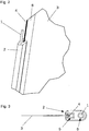
- FIGS. 2 to 5 shown embodiment of the invention, this disadvantage is eliminated without the basic structure of in FIG. 1 vertical awning for it was changed.
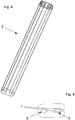
- FIGS. 4 and 5 shown in detail side guide rails 2 are significantly slimmer than those in the prior art according to FIG. 1 Deviating from the side guide rails 2 are here above and below the respective side guide rail 2 attached to the building side.
- FIGS. 2 and 3 each by means of a steel cable 1, which is guided by a longitudinally extending along the respective side guide rail 2 channel 6 and thus forms a longitudinally extending attachment member 1, and which is mounted above and below the respective side guide rail 2 in a known professional manner on a building side mounted holder.
- the holder above the respective side guide rail 2 may be formed at the same time as a carrier or additional box attachment for the box of the vertical awning, which - unlike the in FIG. 1 shown box 11 - no longer supported on the side guide rails 2, but on the two upper-side holders, except for appropriate adjustments (no downwardly projecting pin to connect the guide rails 12, but hook strips for hanging on the top holders or other connection means) but otherwise the in the FIG. 1 shown box 11 may correspond.
- the lower-side holder can be designed in the manner of a wall-mounted spacer with a telescopic or rigid arm, the steel cable 1 is mounted clamped on the boom to train, either directly or via an intermediate spring element.
- the two side guide rails 2 each consist of a one-piece plastic profile, which in addition to the channel 6 for the associated cable 1 has a parallel thereto guide groove 5, which is open to an acting as hanging awning fabric 3 and provided with undercuts 7, see FIG. 5 ,
- On the awning fabric 3 are on both sides as piping acting edge thickenings 4 attached in the form of semi-zipper-like arranged staples, which are advantageously welded to a textile carrier tape 8, which in turn may be welded to the awning fabric 3.
- the edge thickening 4 of the awning fabric 3 are retained on the undercuts 7 serving as Kedernut guide groove 5, so that the curtain is held in total tension.
- weight-weighted drop rod which at its two side ends the local Guide rails 2 may each have fork-like encompassing flank webs and so in contrast to the prior art, can not be performed in the guide rails.
- the textile carrier tape 8 may have a certain elasticity, as for example from the European patent EP 2 335 956 B1 is known to compensate for changes in length in the awning fabric 3.
- This can also be a resilient attachment of the steel cord 1 serve on the top and / or bottom bracket, such as by means of the aforementioned suspension of the steel cord 1 on the lower side holder via a spring element. Variations and modifications of the illustrated embodiment are possible without departing from the scope of the invention as defined in the following claims.
Landscapes
- Engineering & Computer Science (AREA)
- Structural Engineering (AREA)
- Architecture (AREA)
- Civil Engineering (AREA)
- Curtains And Furnishings For Windows Or Doors (AREA)
- Operating, Guiding And Securing Of Roll- Type Closing Members (AREA)
Claims (15)
- Dispositif d'ombrage d'ouverture de bâtiment, comprenant une toile (3) qui peut être relevée et abaissée devant une ouverture de bâtiment ainsi que respectivement un rail de guidage latéral (2) de part et d'autre de la toile (3), dans lequel ladite toile (3) est guidée respectivement dans une rainure de guidage (5) d'un rail de guidage latéral (2), et dans lequel
l'un au moins des deux rails de guidage latéral (2) est traversé par au moins un canal (6) qui s'étend parallèlement à la rainure de guidage dans la direction longitudinale et à travers lequel passe au moins un élément de fixation (1) étendu longitudinalement qui est fixé du côté du bâtiment au-dessus et au-dessous du rail de guidage latéral (2), ou dans lequel
l'un au moins des deux rails de guidage latéral (2) présente en haut et en bas respectivement au moins une ouverture d'introduction qui s'étend parallèlement à la rainure de guidage dans la direction longitudinale dans le rail de guidage latéral, dans lequel au moins un élément de fixation étendu longitudinalement qui est fixé du côté du bâtiment au-dessus ou bien au-dessous du rail de guidage latéral, est introduit respectivement dans les ouvertures d'introduction supérieure et inférieure, et dans lequel
ledit dispositif d'ombrage d'ouverture de bâtiment présente respectivement un support au-dessus et au-dessous dudit au moins un rail de guidage latéral sur lequel est monté ledit un élément de fixation passant à travers ou ledit élément de fixation introduit dans l'ouverture d'introduction respective, support sur lequel ledit élément de fixation respectif est monté de manière à être tendu en traction. - Dispositif d'ombrage d'ouverture de bâtiment selon la revendication 1, caractérisé par le fait que l'élément de fixation respectif est réalisé d'un seul tenant avec le support, dans lequel le support forme conjointement avec l'élément de fixation un appui fixé du côté du bâtiment pour ledit au moins un rail de guidage latéral.
- Dispositif d'ombrage d'ouverture de bâtiment selon la revendication 1 ou 2, caractérisé par le fait que ledit au moins un rail de guidage latéral (2) n'est fixé du côté du bâtiment que sur deux points d'appui, l'un situé au-dessus et l'un situé au-dessous du rail de guidage latéral (2).
- Dispositif d'ombrage d'ouverture de bâtiment selon la revendication 1, 2 ou 3, caractérisé par le fait que ledit au moins un rail de guidage latéral (2) se compose respectivement d'un ou de plusieurs profilés, en particulier de profilés en matière plastique, et présente une rainure de guidage (5) contre-dépouillée en direction de la toile dans laquelle la toile (3) est guidée et maintenue.
- Dispositif d'ombrage d'ouverture de bâtiment selon l'une quelconque des revendications précédentes, caractérisé par le fait que l'élément de fixation respectif est fixé au-dessus et/ou au-dessous dudit au moins un rail de guidage latéral, par l'intermédiaire d'un élément d'amortissement, en caoutchouc ou faisant ressort, tel qu'un pot à ressort, sur le support de manière à être maintenu en tension.
- Dispositif d'ombrage d'ouverture de bâtiment selon l'une quelconque des revendications précédentes, caractérisé par le fait que le support côté supérieur est monté sur une partie latérale d'un coffre d'arbre d'enroulement ou est réalisé d'un seul tenant avec celle-ci.
- Dispositif d'ombrage d'ouverture de bâtiment selon l'une quelconque des revendications précédentes, caractérisé par le fait que l'un au moins des éléments de fixation (1) est un câble (1), en particulier un câble en acier (1), qui s'étend dans le canal (5) associé ou l'ouverture d'introduction associée dudit au moins un rail de guidage latéral (2).
- Dispositif d'ombrage d'ouverture de bâtiment selon la revendication 7, caractérisé par le fait que ledit câble est élastique.
- Dispositif d'ombrage d'ouverture de bâtiment selon la revendication 7 ou 8, caractérisé par le fait que le câble est attaché au-dessus et/ou au-dessous du rail de guidage latéral à un élément d"amortissement, en caoutchouc ou faisant ressort qui, de préférence, est reçu dans un pot monté sur le support.
- Dispositif d'ombrage d'ouverture de bâtiment selon l'une quelconque des revendications précédentes, caractérisé par le fait que l'un au moins des éléments de fixation est une barre, en particulier une barre ronde, de préférence en acier, qui s'étend dans le canal associé ou l'ouverture d'introduction associée dudit au moins un rail de guidage latéral.
- Dispositif d'ombrage d'ouverture de bâtiment selon l'une quelconque des revendications précédentes, caractérisé par le fait que ledit au moins un rail de guidage latéral présente, en tant qu'éléments de fixation, respectivement un tenon introduit dans l'ouverture d'introduction supérieure et un tenon introduit dans l'ouverture d'introduction inférieure.
- Dispositif d'ombrage d'ouverture de bâtiment selon l'une quelconque des revendications précédentes, caractérisé par le fait que le dispositif d'ombrage d'ouverture de bâtiment présente, en tant que store vertical, une toile (3) réalisée comme bande de toile (3) ayant des portions de bourrelet (4) s'étendant le long de ses bords latéraux, dans lequel la toile (3) est guidée et maintenue en traction au moyen desdites portions de bourrelet (4) dans les rainures de guidage (5) contre-dépouillées des deux rails de guidage latéral (2).
- Dispositif d'ombrage d'ouverture de bâtiment selon l'une quelconque des revendications précédentes, caractérisé par le fait qu'une barre d'extrémité est fixée à l'extrémité inférieure de la toile, qui, sur ses deux côtés montrant vers les rails de guidage, présente respectivement deux entretoises de flanc qui font saillie en forme de fourchette en direction du rail de guidage respectif et sont espacées, dans la direction normale, par rapport au plan de la toile au moins de la largeur du rail de guidage et qui embrassent, sur au moins une face de la toile, le rail de guidage y situé.
- Dispositif d'ombrage d'ouverture de bâtiment selon la revendication 13, caractérisé par le fait que ladite barre d'extrémité présente, sur au moins une face de la toile, une entretoise de liaison qui relie entre elles les deux entretoises de flanc faisant saillie en fourchette, sur la face arrière du rail de guidage laquelle montre dans la direction opposée à la toile.
- Dispositif d'ombrage d'ouverture de bâtiment selon l'une quelconque des revendications précédentes, caractérisé par le fait que l'un au moins des rails de guidage présente, sur le côté du canal qui est situé en vis-à-vis de la rainure de guidage, une rainure supplémentaire de guidage pour une toile d'un autre dispositif d'ombrage d'ouverture de bâtiment disposé latéralement à côté du dispositif d'ombrage d'ouverture de bâtiment.
Priority Applications (1)
| Application Number | Priority Date | Filing Date | Title |
|---|---|---|---|
| EP15000030.5A EP3043018B1 (fr) | 2015-01-09 | 2015-01-09 | Dispositif d'ombrage d'une ouverture de bâtiment avec un rail de guidage latéral |
Applications Claiming Priority (1)
| Application Number | Priority Date | Filing Date | Title |
|---|---|---|---|
| EP15000030.5A EP3043018B1 (fr) | 2015-01-09 | 2015-01-09 | Dispositif d'ombrage d'une ouverture de bâtiment avec un rail de guidage latéral |
Publications (2)
| Publication Number | Publication Date |
|---|---|
| EP3043018A1 EP3043018A1 (fr) | 2016-07-13 |
| EP3043018B1 true EP3043018B1 (fr) | 2016-12-14 |
Family
ID=52338970
Family Applications (1)
| Application Number | Title | Priority Date | Filing Date |
|---|---|---|---|
| EP15000030.5A Active EP3043018B1 (fr) | 2015-01-09 | 2015-01-09 | Dispositif d'ombrage d'une ouverture de bâtiment avec un rail de guidage latéral |
Country Status (1)
| Country | Link |
|---|---|
| EP (1) | EP3043018B1 (fr) |
Cited By (1)
| Publication number | Priority date | Publication date | Assignee | Title |
|---|---|---|---|---|
| EP4575175A1 (fr) | 2023-12-19 | 2025-06-25 | Roma Kg | Store vertical et rail de guidage latéral pour celui-ci |
Family Cites Families (6)
| Publication number | Priority date | Publication date | Assignee | Title |
|---|---|---|---|---|
| DE7002243U (de) | 1970-01-23 | 1970-05-27 | Griesser Ag | Raffjalousie. |
| WO2004069011A1 (fr) * | 2003-01-27 | 2004-08-19 | Wayne-Dalton Corporation | Rideau coupe-vent |
| CA2638848A1 (fr) | 2007-09-03 | 2009-03-03 | Hunter Douglas Industries B.V. | Dispositif d'ancrage |
| DE102009007682B4 (de) | 2009-02-05 | 2013-03-07 | Roma Kg | Vorrichtung zum Verschließen einer Gebäudeöffnung |
| FR2953768B1 (fr) | 2009-12-15 | 2012-11-23 | Acs France Sas | Dispositif d'occultation, vehicule et procede de fabrication correspondants. |
| ES2434105B1 (es) | 2012-05-11 | 2014-07-24 | Amiserru, S.L. | Puerta de apertura rápida |
-
2015
- 2015-01-09 EP EP15000030.5A patent/EP3043018B1/fr active Active
Non-Patent Citations (1)
| Title |
|---|
| None * |
Cited By (1)
| Publication number | Priority date | Publication date | Assignee | Title |
|---|---|---|---|---|
| EP4575175A1 (fr) | 2023-12-19 | 2025-06-25 | Roma Kg | Store vertical et rail de guidage latéral pour celui-ci |
Also Published As
| Publication number | Publication date |
|---|---|
| EP3043018A1 (fr) | 2016-07-13 |
Similar Documents
| Publication | Publication Date | Title |
|---|---|---|
| DE102012003591A1 (de) | Führungsschiene für eine Senkrechtmarkise und Senkrechtmarkise | |
| EP2826945B1 (fr) | Pare-soleil vertical | |
| DE102009027497B4 (de) | Fensterclip für Fensterbehang | |
| EP0534261A2 (fr) | Store pour une surface (en verre) non rectangulaire | |
| EP3043018A1 (fr) | Dispositif d'ombrage d'une ouverture de bâtiment avec un rail de guidage latéral | |
| DE102016105890A1 (de) | Rahmenprofil zur reversiblen Anordnung eines Objektes | |
| DE8909836U1 (de) | Führungsvorrichtung eines Vorhanges, insbesondere einer Falt- oder Lamellenjalousie oder eines Rollos | |
| EP2281995B1 (fr) | Volet Roulant | |
| AT517909B1 (de) | Schutzvorrichtung | |
| DE102013003012A1 (de) | Flächenvorhangsystem | |
| DE102013019243B4 (de) | Seilbremse, Spannset und Vorhangsystem | |
| CH650305A5 (de) | Markise. | |
| EP1936062B1 (fr) | Guidage d'un profilé d'extension | |
| DE102007040518A1 (de) | Raffvorhang | |
| EP3805514B1 (fr) | Dispositif de fixation pour les dispositifs de protection de la lumière et/ou de la vue | |
| DE102004055746A1 (de) | Vorrichtung zur Abschattung eines Wintergartens, einer Pergola o. dgl. | |
| DE202006021144U1 (de) | Senkrechtbeschattung | |
| DE202023103274U1 (de) | Befestigung einer schnurgespannten Cafehausgardine | |
| EP4575175A1 (fr) | Store vertical et rail de guidage latéral pour celui-ci | |
| DE7426155U (de) | Lamellenstore mit lotrecht angeordneten, seitlich verschiebbaren und um Ihre Längsachse gemeinsam begrenzt verschwenkbaren Lamellen | |
| DE202008010876U1 (de) | Einrichtung an Sonnen- und Blickschutzvorrichtungen | |
| DE1654034C3 (de) | Kopfschiene einer raffbaren Lamellenjalousie | |
| AT14324U1 (de) | Gebäudeöffnungsverschattungsvorichtung sowie Kopfleistenmodul und Fertigungsverfahren dafür | |
| DE19908926A1 (de) | Textiles Tragmittel für Lamellenjalousien | |
| DE9005275U1 (de) | Führungsvorrichtung einer Falt- oder Lamellenjalousie |
Legal Events
| Date | Code | Title | Description |
|---|---|---|---|
| PUAI | Public reference made under article 153(3) epc to a published international application that has entered the european phase |
Free format text: ORIGINAL CODE: 0009012 |
|
| 17P | Request for examination filed |
Effective date: 20151008 |
|
| AK | Designated contracting states |
Kind code of ref document: A1 Designated state(s): AL AT BE BG CH CY CZ DE DK EE ES FI FR GB GR HR HU IE IS IT LI LT LU LV MC MK MT NL NO PL PT RO RS SE SI SK SM TR |
|
| AX | Request for extension of the european patent |
Extension state: BA ME |
|
| GRAP | Despatch of communication of intention to grant a patent |
Free format text: ORIGINAL CODE: EPIDOSNIGR1 |
|
| RIC1 | Information provided on ipc code assigned before grant |
Ipc: E06B 9/40 20060101ALN20160719BHEP Ipc: E06B 9/58 20060101AFI20160719BHEP |
|
| INTG | Intention to grant announced |
Effective date: 20160811 |
|
| GRAS | Grant fee paid |
Free format text: ORIGINAL CODE: EPIDOSNIGR3 |
|
| GRAA | (expected) grant |
Free format text: ORIGINAL CODE: 0009210 |
|
| AK | Designated contracting states |
Kind code of ref document: B1 Designated state(s): AL AT BE BG CH CY CZ DE DK EE ES FI FR GB GR HR HU IE IS IT LI LT LU LV MC MK MT NL NO PL PT RO RS SE SI SK SM TR |
|
| REG | Reference to a national code |
Ref country code: GB Ref legal event code: FG4D Free format text: NOT ENGLISH |
|
| REG | Reference to a national code |
Ref country code: CH Ref legal event code: EP |
|
| REG | Reference to a national code |
Ref country code: IE Ref legal event code: FG4D Free format text: LANGUAGE OF EP DOCUMENT: GERMAN Ref country code: NL Ref legal event code: FP |
|
| REG | Reference to a national code |
Ref country code: AT Ref legal event code: REF Ref document number: 853762 Country of ref document: AT Kind code of ref document: T Effective date: 20170115 |
|
| REG | Reference to a national code |
Ref country code: DE Ref legal event code: R096 Ref document number: 502015000379 Country of ref document: DE |
|
| REG | Reference to a national code |
Ref country code: FR Ref legal event code: PLFP Year of fee payment: 3 |
|
| PG25 | Lapsed in a contracting state [announced via postgrant information from national office to epo] |
Ref country code: LV Free format text: LAPSE BECAUSE OF FAILURE TO SUBMIT A TRANSLATION OF THE DESCRIPTION OR TO PAY THE FEE WITHIN THE PRESCRIBED TIME-LIMIT Effective date: 20161214 |
|
| REG | Reference to a national code |
Ref country code: LT Ref legal event code: MG4D |
|
| PG25 | Lapsed in a contracting state [announced via postgrant information from national office to epo] |
Ref country code: SE Free format text: LAPSE BECAUSE OF FAILURE TO SUBMIT A TRANSLATION OF THE DESCRIPTION OR TO PAY THE FEE WITHIN THE PRESCRIBED TIME-LIMIT Effective date: 20161214 Ref country code: NO Free format text: LAPSE BECAUSE OF FAILURE TO SUBMIT A TRANSLATION OF THE DESCRIPTION OR TO PAY THE FEE WITHIN THE PRESCRIBED TIME-LIMIT Effective date: 20170314 Ref country code: GR Free format text: LAPSE BECAUSE OF FAILURE TO SUBMIT A TRANSLATION OF THE DESCRIPTION OR TO PAY THE FEE WITHIN THE PRESCRIBED TIME-LIMIT Effective date: 20170315 Ref country code: LT Free format text: LAPSE BECAUSE OF FAILURE TO SUBMIT A TRANSLATION OF THE DESCRIPTION OR TO PAY THE FEE WITHIN THE PRESCRIBED TIME-LIMIT Effective date: 20161214 |
|
| PG25 | Lapsed in a contracting state [announced via postgrant information from national office to epo] |
Ref country code: BE Free format text: LAPSE BECAUSE OF NON-PAYMENT OF DUE FEES Effective date: 20170131 Ref country code: FI Free format text: LAPSE BECAUSE OF FAILURE TO SUBMIT A TRANSLATION OF THE DESCRIPTION OR TO PAY THE FEE WITHIN THE PRESCRIBED TIME-LIMIT Effective date: 20161214 Ref country code: HR Free format text: LAPSE BECAUSE OF FAILURE TO SUBMIT A TRANSLATION OF THE DESCRIPTION OR TO PAY THE FEE WITHIN THE PRESCRIBED TIME-LIMIT Effective date: 20161214 Ref country code: RS Free format text: LAPSE BECAUSE OF FAILURE TO SUBMIT A TRANSLATION OF THE DESCRIPTION OR TO PAY THE FEE WITHIN THE PRESCRIBED TIME-LIMIT Effective date: 20161214 |
|
| PG25 | Lapsed in a contracting state [announced via postgrant information from national office to epo] |
Ref country code: SK Free format text: LAPSE BECAUSE OF FAILURE TO SUBMIT A TRANSLATION OF THE DESCRIPTION OR TO PAY THE FEE WITHIN THE PRESCRIBED TIME-LIMIT Effective date: 20161214 Ref country code: RO Free format text: LAPSE BECAUSE OF FAILURE TO SUBMIT A TRANSLATION OF THE DESCRIPTION OR TO PAY THE FEE WITHIN THE PRESCRIBED TIME-LIMIT Effective date: 20161214 Ref country code: CZ Free format text: LAPSE BECAUSE OF FAILURE TO SUBMIT A TRANSLATION OF THE DESCRIPTION OR TO PAY THE FEE WITHIN THE PRESCRIBED TIME-LIMIT Effective date: 20161214 Ref country code: IS Free format text: LAPSE BECAUSE OF FAILURE TO SUBMIT A TRANSLATION OF THE DESCRIPTION OR TO PAY THE FEE WITHIN THE PRESCRIBED TIME-LIMIT Effective date: 20170414 Ref country code: EE Free format text: LAPSE BECAUSE OF FAILURE TO SUBMIT A TRANSLATION OF THE DESCRIPTION OR TO PAY THE FEE WITHIN THE PRESCRIBED TIME-LIMIT Effective date: 20161214 |
|
| PG25 | Lapsed in a contracting state [announced via postgrant information from national office to epo] |
Ref country code: BG Free format text: LAPSE BECAUSE OF FAILURE TO SUBMIT A TRANSLATION OF THE DESCRIPTION OR TO PAY THE FEE WITHIN THE PRESCRIBED TIME-LIMIT Effective date: 20170314 Ref country code: SM Free format text: LAPSE BECAUSE OF FAILURE TO SUBMIT A TRANSLATION OF THE DESCRIPTION OR TO PAY THE FEE WITHIN THE PRESCRIBED TIME-LIMIT Effective date: 20161214 Ref country code: ES Free format text: LAPSE BECAUSE OF FAILURE TO SUBMIT A TRANSLATION OF THE DESCRIPTION OR TO PAY THE FEE WITHIN THE PRESCRIBED TIME-LIMIT Effective date: 20161214 Ref country code: PT Free format text: LAPSE BECAUSE OF FAILURE TO SUBMIT A TRANSLATION OF THE DESCRIPTION OR TO PAY THE FEE WITHIN THE PRESCRIBED TIME-LIMIT Effective date: 20170414 Ref country code: PL Free format text: LAPSE BECAUSE OF FAILURE TO SUBMIT A TRANSLATION OF THE DESCRIPTION OR TO PAY THE FEE WITHIN THE PRESCRIBED TIME-LIMIT Effective date: 20161214 Ref country code: IT Free format text: LAPSE BECAUSE OF FAILURE TO SUBMIT A TRANSLATION OF THE DESCRIPTION OR TO PAY THE FEE WITHIN THE PRESCRIBED TIME-LIMIT Effective date: 20161214 |
|
| REG | Reference to a national code |
Ref country code: DE Ref legal event code: R097 Ref document number: 502015000379 Country of ref document: DE |
|
| PG25 | Lapsed in a contracting state [announced via postgrant information from national office to epo] |
Ref country code: MC Free format text: LAPSE BECAUSE OF FAILURE TO SUBMIT A TRANSLATION OF THE DESCRIPTION OR TO PAY THE FEE WITHIN THE PRESCRIBED TIME-LIMIT Effective date: 20161214 |
|
| PLBE | No opposition filed within time limit |
Free format text: ORIGINAL CODE: 0009261 |
|
| STAA | Information on the status of an ep patent application or granted ep patent |
Free format text: STATUS: NO OPPOSITION FILED WITHIN TIME LIMIT |
|
| REG | Reference to a national code |
Ref country code: IE Ref legal event code: MM4A |
|
| 26N | No opposition filed |
Effective date: 20170915 |
|
| PG25 | Lapsed in a contracting state [announced via postgrant information from national office to epo] |
Ref country code: DK Free format text: LAPSE BECAUSE OF FAILURE TO SUBMIT A TRANSLATION OF THE DESCRIPTION OR TO PAY THE FEE WITHIN THE PRESCRIBED TIME-LIMIT Effective date: 20161214 Ref country code: LU Free format text: LAPSE BECAUSE OF NON-PAYMENT OF DUE FEES Effective date: 20170109 |
|
| REG | Reference to a national code |
Ref country code: FR Ref legal event code: PLFP Year of fee payment: 4 |
|
| REG | Reference to a national code |
Ref country code: BE Ref legal event code: MM Effective date: 20170131 |
|
| PG25 | Lapsed in a contracting state [announced via postgrant information from national office to epo] |
Ref country code: SI Free format text: LAPSE BECAUSE OF FAILURE TO SUBMIT A TRANSLATION OF THE DESCRIPTION OR TO PAY THE FEE WITHIN THE PRESCRIBED TIME-LIMIT Effective date: 20161214 Ref country code: IE Free format text: LAPSE BECAUSE OF NON-PAYMENT OF DUE FEES Effective date: 20170109 |
|
| REG | Reference to a national code |
Ref country code: CH Ref legal event code: PL |
|
| PG25 | Lapsed in a contracting state [announced via postgrant information from national office to epo] |
Ref country code: MT Free format text: LAPSE BECAUSE OF FAILURE TO SUBMIT A TRANSLATION OF THE DESCRIPTION OR TO PAY THE FEE WITHIN THE PRESCRIBED TIME-LIMIT Effective date: 20161214 |
|
| PG25 | Lapsed in a contracting state [announced via postgrant information from national office to epo] |
Ref country code: LI Free format text: LAPSE BECAUSE OF NON-PAYMENT OF DUE FEES Effective date: 20180131 Ref country code: CH Free format text: LAPSE BECAUSE OF NON-PAYMENT OF DUE FEES Effective date: 20180131 |
|
| PG25 | Lapsed in a contracting state [announced via postgrant information from national office to epo] |
Ref country code: HU Free format text: LAPSE BECAUSE OF FAILURE TO SUBMIT A TRANSLATION OF THE DESCRIPTION OR TO PAY THE FEE WITHIN THE PRESCRIBED TIME-LIMIT; INVALID AB INITIO Effective date: 20150109 |
|
| GBPC | Gb: european patent ceased through non-payment of renewal fee |
Effective date: 20190109 |
|
| PG25 | Lapsed in a contracting state [announced via postgrant information from national office to epo] |
Ref country code: CY Free format text: LAPSE BECAUSE OF FAILURE TO SUBMIT A TRANSLATION OF THE DESCRIPTION OR TO PAY THE FEE WITHIN THE PRESCRIBED TIME-LIMIT Effective date: 20161214 |
|
| PG25 | Lapsed in a contracting state [announced via postgrant information from national office to epo] |
Ref country code: MK Free format text: LAPSE BECAUSE OF FAILURE TO SUBMIT A TRANSLATION OF THE DESCRIPTION OR TO PAY THE FEE WITHIN THE PRESCRIBED TIME-LIMIT Effective date: 20161214 |
|
| PG25 | Lapsed in a contracting state [announced via postgrant information from national office to epo] |
Ref country code: GB Free format text: LAPSE BECAUSE OF NON-PAYMENT OF DUE FEES Effective date: 20190109 |
|
| PG25 | Lapsed in a contracting state [announced via postgrant information from national office to epo] |
Ref country code: TR Free format text: LAPSE BECAUSE OF FAILURE TO SUBMIT A TRANSLATION OF THE DESCRIPTION OR TO PAY THE FEE WITHIN THE PRESCRIBED TIME-LIMIT Effective date: 20161214 |
|
| PG25 | Lapsed in a contracting state [announced via postgrant information from national office to epo] |
Ref country code: AL Free format text: LAPSE BECAUSE OF FAILURE TO SUBMIT A TRANSLATION OF THE DESCRIPTION OR TO PAY THE FEE WITHIN THE PRESCRIBED TIME-LIMIT Effective date: 20161214 |
|
| PGFP | Annual fee paid to national office [announced via postgrant information from national office to epo] |
Ref country code: AT Payment date: 20240118 Year of fee payment: 10 |
|
| REG | Reference to a national code |
Ref country code: AT Ref legal event code: MM01 Ref document number: 853762 Country of ref document: AT Kind code of ref document: T Effective date: 20250109 |
|
| PG25 | Lapsed in a contracting state [announced via postgrant information from national office to epo] |
Ref country code: AT Free format text: LAPSE BECAUSE OF NON-PAYMENT OF DUE FEES Effective date: 20250109 |
|
| PGFP | Annual fee paid to national office [announced via postgrant information from national office to epo] |
Ref country code: NL Payment date: 20260121 Year of fee payment: 12 |
|
| PGFP | Annual fee paid to national office [announced via postgrant information from national office to epo] |
Ref country code: DE Payment date: 20260131 Year of fee payment: 12 |
|
| PGFP | Annual fee paid to national office [announced via postgrant information from national office to epo] |
Ref country code: FR Payment date: 20260127 Year of fee payment: 12 |