EP3043082B1 - Joint étanche à la poussière - Google Patents
Joint étanche à la poussière Download PDFInfo
- Publication number
- EP3043082B1 EP3043082B1 EP14843081.2A EP14843081A EP3043082B1 EP 3043082 B1 EP3043082 B1 EP 3043082B1 EP 14843081 A EP14843081 A EP 14843081A EP 3043082 B1 EP3043082 B1 EP 3043082B1
- Authority
- EP
- European Patent Office
- Prior art keywords
- lip
- rib
- seal
- leading end
- bearing
- Prior art date
- Legal status (The legal status is an assumption and is not a legal conclusion. Google has not performed a legal analysis and makes no representation as to the accuracy of the status listed.)
- Active
Links
Images



Classifications
-
- F—MECHANICAL ENGINEERING; LIGHTING; HEATING; WEAPONS; BLASTING
- F16—ENGINEERING ELEMENTS AND UNITS; GENERAL MEASURES FOR PRODUCING AND MAINTAINING EFFECTIVE FUNCTIONING OF MACHINES OR INSTALLATIONS; THERMAL INSULATION IN GENERAL
- F16C—SHAFTS; FLEXIBLE SHAFTS; ELEMENTS OR CRANKSHAFT MECHANISMS; ROTARY BODIES OTHER THAN GEARING ELEMENTS; BEARINGS
- F16C33/00—Parts of bearings; Special methods for making bearings or parts thereof
- F16C33/72—Sealings
- F16C33/76—Sealings of ball or roller bearings
- F16C33/78—Sealings of ball or roller bearings with a diaphragm, disc, or ring, with or without resilient members
- F16C33/7886—Sealings of ball or roller bearings with a diaphragm, disc, or ring, with or without resilient members mounted outside the gap between the inner and outer races, e.g. sealing rings mounted to an end face or outer surface of a race
-
- F—MECHANICAL ENGINEERING; LIGHTING; HEATING; WEAPONS; BLASTING
- F16—ENGINEERING ELEMENTS AND UNITS; GENERAL MEASURES FOR PRODUCING AND MAINTAINING EFFECTIVE FUNCTIONING OF MACHINES OR INSTALLATIONS; THERMAL INSULATION IN GENERAL
- F16C—SHAFTS; FLEXIBLE SHAFTS; ELEMENTS OR CRANKSHAFT MECHANISMS; ROTARY BODIES OTHER THAN GEARING ELEMENTS; BEARINGS
- F16C33/00—Parts of bearings; Special methods for making bearings or parts thereof
- F16C33/30—Parts of ball or roller bearings
- F16C33/66—Special parts or details in view of lubrication
- F16C33/6603—Special parts or details in view of lubrication with grease as lubricant
- F16C33/6607—Retaining the grease in or near the bearing
- F16C33/6618—Retaining the grease in or near the bearing in a reservoir in the sealing means
-
- F—MECHANICAL ENGINEERING; LIGHTING; HEATING; WEAPONS; BLASTING
- F16—ENGINEERING ELEMENTS AND UNITS; GENERAL MEASURES FOR PRODUCING AND MAINTAINING EFFECTIVE FUNCTIONING OF MACHINES OR INSTALLATIONS; THERMAL INSULATION IN GENERAL
- F16C—SHAFTS; FLEXIBLE SHAFTS; ELEMENTS OR CRANKSHAFT MECHANISMS; ROTARY BODIES OTHER THAN GEARING ELEMENTS; BEARINGS
- F16C33/00—Parts of bearings; Special methods for making bearings or parts thereof
- F16C33/72—Sealings
- F16C33/726—Sealings with means to vent the interior of the bearing
-
- F—MECHANICAL ENGINEERING; LIGHTING; HEATING; WEAPONS; BLASTING
- F16—ENGINEERING ELEMENTS AND UNITS; GENERAL MEASURES FOR PRODUCING AND MAINTAINING EFFECTIVE FUNCTIONING OF MACHINES OR INSTALLATIONS; THERMAL INSULATION IN GENERAL
- F16J—PISTONS; CYLINDERS; SEALINGS
- F16J15/00—Sealings
- F16J15/16—Sealings between relatively-moving surfaces
- F16J15/32—Sealings between relatively-moving surfaces with elastic sealings, e.g. O-rings
- F16J15/324—Arrangements for lubrication or cooling of the sealing itself
-
- F—MECHANICAL ENGINEERING; LIGHTING; HEATING; WEAPONS; BLASTING
- F16—ENGINEERING ELEMENTS AND UNITS; GENERAL MEASURES FOR PRODUCING AND MAINTAINING EFFECTIVE FUNCTIONING OF MACHINES OR INSTALLATIONS; THERMAL INSULATION IN GENERAL
- F16C—SHAFTS; FLEXIBLE SHAFTS; ELEMENTS OR CRANKSHAFT MECHANISMS; ROTARY BODIES OTHER THAN GEARING ELEMENTS; BEARINGS
- F16C19/00—Bearings with rolling contact, for exclusively rotary movement
-
- F—MECHANICAL ENGINEERING; LIGHTING; HEATING; WEAPONS; BLASTING
- F16—ENGINEERING ELEMENTS AND UNITS; GENERAL MEASURES FOR PRODUCING AND MAINTAINING EFFECTIVE FUNCTIONING OF MACHINES OR INSTALLATIONS; THERMAL INSULATION IN GENERAL
- F16C—SHAFTS; FLEXIBLE SHAFTS; ELEMENTS OR CRANKSHAFT MECHANISMS; ROTARY BODIES OTHER THAN GEARING ELEMENTS; BEARINGS
- F16C2326/00—Articles relating to transporting
- F16C2326/01—Parts of vehicles in general
- F16C2326/02—Wheel hubs or castors
-
- F—MECHANICAL ENGINEERING; LIGHTING; HEATING; WEAPONS; BLASTING
- F16—ENGINEERING ELEMENTS AND UNITS; GENERAL MEASURES FOR PRODUCING AND MAINTAINING EFFECTIVE FUNCTIONING OF MACHINES OR INSTALLATIONS; THERMAL INSULATION IN GENERAL
- F16C—SHAFTS; FLEXIBLE SHAFTS; ELEMENTS OR CRANKSHAFT MECHANISMS; ROTARY BODIES OTHER THAN GEARING ELEMENTS; BEARINGS
- F16C33/00—Parts of bearings; Special methods for making bearings or parts thereof
- F16C33/72—Sealings
- F16C33/76—Sealings of ball or roller bearings
- F16C33/80—Labyrinth sealings
- F16C33/805—Labyrinth sealings in addition to other sealings, e.g. dirt guards to protect sealings with sealing lips
Definitions
- the present invention relates to a dust seal according to the preamble of claim 1 utilizing a sealing technology.
- the dust seal according to the present invention is used, for example, in a hub bearing portion for a vehicle such as a motor vehicle, or is used in a bearing portion for the other general industrial devices.
- a dust seal 61 with an interference having a sliding lip 62 is advantageous as shown.
- a lip rubber portion deforms due to pressure fluctuation (generation of negative pressure) caused by temperature change within a bearing, a lip contact state is deteriorated, and a sliding torque is increased.
- a dust seal 61 which is installed to an outer side of a bearing portion of a device and inhibits dusts in an external portion A of the device from entering into a bearing side B in the device, the dust seal 61 having a seal lip 62 of a side lip structure which slidably comes into close contact with the other member 71, there is a risk that the lip 62 deforms due to generation of the negative pressure in the bearing side B in the machine, the lip 62 entirely abuts on the other member 71 and the sliding torque is increased.
- Patent Document 2 A generic dust seal according to the preamble of claim 1 is shown by Patent Document 2. Further dust seals are shown by Patent Documents 3 to 5.
- the present invention is made by taking the above points into consideration, and an object of the present invention is to provide a dust seal having an improved durability and efficiency.
- a dust seal is provided having a function of dissolving negative pressure when the negative pressure is generated in a bearing side in a device as well as achieving an excellent sealing performance at the steady operating time of the bearing portion, thereby allowing to inhibit sliding torque from being increased due to deterioration of a lip contact state, and further structured such that a rib provided on a surface of the lip for valve opening the lip stably comes into contact with the other member.
- a dust seal according to the present invention is a dust seal installed to an outer side of a bearing portion of a device and inhibiting dusts in an external portion of the device from entering into a bearing side in the device, the dust seal having a seal lip of a side lip structure which slidably comes into close contact with the other member, wherein a plurality of ribs are equally distributed on a surface in an inner side of the device of the seal lip, a lip leading end of the seal lip comes into close contact with the other member over a whole periphery at the steady operating time of the bearing portion, the lip leading end circumferentially opens valve partly around the rib serving as a supporting point of a lever due to deformation of the seal lip with negative pressure when the negative pressure is generated in the bearing portion, the lip leading end closes valve due to returning motion of the seal lip when the negative pressure is dissolved, and the rib is formed into a circular arc shape in a contact portion with the other member in a cross sectional shape when the rib
- a dust seal according to the present invention is the dust seal mentioned above, wherein a grease retention portion capable of storing a lubricating grease and formed into a concave shape is provided on a rising surface in the lip leading end side of the rib or a surface in the device inner side of the seal lip from the rising surface to the lip leading end.
- the dust seal is used in a hub bearing portion for a vehicle such as a motor vehicle, and is installed to an outer side of a seal for a hub bearing.
- the dust seal according to the present invention having the structure mentioned above, a plurality of ribs are equally distributed on the surface in the device inner side of the seal lip of the side lip structure. As a result, the dust seal operates as follows.
- the seal lip When the negative pressure is generated in the bearing portion and reaches a predetermined value, the seal lip is deformed by the negative pressure, and the lip leading end circumferentially opens valve partly around the rib serving as the supporting point of the lever. As a result, since ambient air (atmospheric pressure) flows into from the valve opening position, the negative pressure state is dissolved.
- the shape of the rib is particularized, that is, the cross sectional shape of the contact portion with the other member in the rib is formed into the circular arc shape, the rib is formed into a shape that the rib widely comes into surface contact with the other member. Therefore, since the contact width of the rib with the other member is secured to be wider in comparison with the case that the rib comes into line contact with the other member, the rib is hard to be affected by a sliding surface shape, eccentricity, inclination and assembled condition of the other member, and a contact state of the rib with the other member is stabilized. Accordingly, there is set a condition that the operation and effect of dissolving the internal negative pressure (valve opening with the lip leading end) as mentioned above can be easily achieved.
- the rib may be structured such as to always come into contact with the other member, or may be structured such as to be away from the other member at the steady operating time and come into contact with the other member only when the negative pressure is generated. In any case, since the rib slides against the other member, there is a risk that excessive wear is generated due to lack of lubrication. Then, in order to devise a countermeasure, it is preferable to supply the grease for lubrication to the contact portion with the other member in the rib.
- the grease retention portion capable of storing the lubricating grease and formed into the concave shape is provided on the rising surface in the lip leading end side of the rib or the surface in the device inner side of the seal lip from the rising surface to the lip leading end, and the grease is supplied to the contact portion from the grease retention portion. Therefore, since the grease is supplied to the contact portion with the other member in the rib according to the structure, it is possible to inhibit the excessive wear from being generated in the contact portion due to the lack of lubrication.
- the dust seal according to the present invention is used, for example, in the hub bearing for the vehicle such as the motor vehicle, and is installed to the outer side of the seal for the hub bearing. Therefore, in the dust seal (the hub bearing externally attached dust seal) used in this kind of intended use, the operations and effects of the present invention can be obtained.
- the present invention achieves the following effects.
- the lip leading end of the seal lip comes into close contact with the other member over a whole periphery at the steady operating time of the bearing portion as mentioned above, it is possible to achieve the excellent sealing performance. Further, since the seal lip opens valve on the basis of the action of the lever by the rib when the negative pressure is generated in the bearing portion, it is possible to dissolve the negative pressure, and it is accordingly possible to inhibit the sliding torque from being increased due to the deterioration of the lip contact state.
- the shape of the rib is particularized, that is, the cross sectional shape of the contact portion in the rib is formed into the circular arc shape so as to be formed into the shape that widely comes into surface contact with the other member, the contact state of the rib with the other member is stabilized. Therefore, the rib tends to operate as the supporting point of the lever, and the lip leading end tends to open valve.
- the grease is supplied to the contact portion of the rib from the grease retention portion by the provision of the concave grease retention portion, it is possible to inhibit the excessive wear from being generated in the rib due to the lack of lubrication. Sufficient lubrication of the contact portion of the rib can contribute the torque reduction and the squeal resistance (suppression of sliding contact noise generation).
- the dust seal according to the present invention is used in the hub bearing portion for the vehicle such as the motor vehicle and is installed to the outer side of the seal for the hub bearing, the operations and effects of the present invention can be obtained in the dust seal (the hub bearing externally attached dust seal) which is used in this kind of intended use.
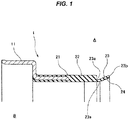
- Fig. 1 shows a dust seal 1 according to the example.
- the dust seal according to the example is installed to an outer side of a bearing portion of a device, is structured such as to inhibit dusts in an external portion A of the device from entering into a bearing side B in the device, and has a seal lip 23 of a side lip structure which slidably comes into close contact with the other member.
- the dust seal 1 according to the example is used in a hub bearing portion for a vehicle such as a motor vehicle and is installed to an outer side of a seal for a hub bearing, in the same manner as the prior art ( Fig. 7 ) mentioned above.
- the dust seal 1 is first of all provided as a whole with an attachment ring 11 made from metal which is fitted to an installation member such as a housing of a device or an outer race of a hub bearing portion, a rubber-like elastic body 21 is attached (vulcanization bonded) to the attachment ring 11, a cylindrical lip retention portion 22 is formed by the rubber-like elastic body 21, and a seal lip 23 having a side lip structure is integrally formed in a leading end of the lip retention portion 22.
- the seal lip 23 is formed into a taper shape (a trumpet shape) so that a diameter is enlarged little by little from a lip base end 23a to a lip leading end 23b, and slidably comes into close contact with a surface (an end surface in an axial direction) of the other member 71 with an inner peripheral edge portion of the lip leading end 23b. Since a constricted portion 23c which is thinner in comparison with the lip retention portion 22 is provided on a surface in an outer side of the device (an outer peripheral surface) of the lip base end 23a, the seal lip 23 tends to be deformed, and tends to follow to a surface (a curved surface) of the other member 71.
- a plurality of ribs 24 are provided in an equally distributed manner (for example, six ribs 24 are circumferentially distributed equally) on a surface (an inner peripheral surface) in a device inner side of the seal lip 23, and the dust seal 1 operates as follows on the basis of the provision of the ribs 24 as mentioned above.
- the lip leading end 23b of the seal lip 23 comes into close contact with the other member 71 over a whole periphery. Therefore, an excellent sealing performance can be achieved so as to prevent the external foreign maters such as the water, the muddy water or the dusts in the external portion A of the device from entering into the bearing side B in the device.
- the seal lip 23 When the negative pressure is generated in the bearing side B in the device and reaches a predetermined value, the seal lip 23 is deformed with the negative pressure, and the lip leading end 23b circumferentially opens valve partly around the rib 24 serving as a supporting point of a lever. More specifically, when the negative pressure is generated in the bearing side B in the device and the negative pressure reaches the predetermined value as shown in Fig.
- the seal lip 23 is deformed in a direction of an arrow D so as to be sucked by the negative pressure, the lip leading end 23b is lifted up in a direction of an arrow E circumferentially partly (at a position near the rib 24) around the lib 24 under a contact state with the other member 71, the rib 24 serving as the supporting point of the lever, and moves away from the other member 71, and a gap c is formed in relation to the other member 71. Therefore, since the ambient air (the atmospheric pressure) flows into the bearing side B in the device from the gap c, the negative pressure state of the bearing side B in the device is dissolved. Since the rib 24 comes into contact with the other member 71 at the ambient air flowing time, the ambient air flows into through both lateral sides (both sides in a circumferential direction) of the rib 24.
- the seal lip 23 with the rib having the structure mentioned above the excellent sealing performance can be achieved, and the function of dissolving the negative pressure generated in the bearing side B in the device is provided. As a result, it is possible to inhibit the sliding torque from being increased due to the deterioration of the contact state of the seal lip 23 with the other member 71.
- the rib 24 is structured as follows in detail.
- the rib 24 is formed so that its height becomes higher little by little from the lip base end 23a side to the lip leading end 23b side, as shown in Fig. 2 . Further, the rib 24 is formed so that a lateral width (a width in a circumferential direction) is approximately constant.
- the rib 24 is formed so that a contact portion 24a with the other member 71 is a circular arc shape in a cross sectional shape when the rib 24 is cut by a plane including a center axis of the dust seal 1, whereby the rib 24 can widely come into surface contact with the other member with a predetermined contact width w as shown in Fig. 3 .
- the cross sectional shape of the rib is formed into an approximately triangular shape, however, an apex portion of the triangle constructing the contact portion 24a is not formed into a peak shape but is formed into a circular arc cross sectional shape. As a result, the rib can widely come into surface contact with the other member 71 with the predetermined contact width w.
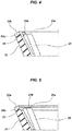
- a grease retention portion 25 capable of storing a lubricating grease such as a bearing grease and formed into a concave shape is provided in a rising surface 24b in the lip leading end 23b side of the rib 24, and it is possible to supply the grease for lubricating from the grease retention portion 25 to the contact portion 24a.
- the concave grease retention portion 25 may be provided on a surface (an inner peripheral surface) in the device inner side of the seal lip 23 from the rising surface 24b of the rib 24 to the lip leading end 23b as follows, in addition to the provision in the rising surface 24b in the lip leading end 23b side of the rib 24.
- a grease retention portion 25A formed into a concave shape is provided as a circumferential part on a surface (an inner peripheral surface) in the device inner side of the seal lip 23 from the rising surface 24b of the rib 24 to the lip leading end 23b, so as to be aligned with the rib 24 at a circumferential position.
- a grease retention portion 25B formed into a concave shape is provided as an annular shaped part on a surface (an inner peripheral surface) in the device inner side of the seal lip 23 from the rising surface 24b of the rib 24 to the lip leading end 23b.
- a grease retention portion 25A formed into a concave shape is provided as a circumferential part on a surface (an inner peripheral surface) in the device inner side of the seal lip 23 from the rising surface 24b of the rib 24 to the lip leading end 23b, so as to be aligned with the rib 24 at a circumferential position, and an annular grease retention portion 25B is additionally provided.
- the circumferentially partial grease retention portion 25A is set to be deeper, and the grease collected by the annular grease retention portion 25B is supplied from the circumferentially partial grease retention portion 25A to the contact portion 24a.
- micro concavities and convexities may be provided at least on the grease retention surface, thereby making the grease to be easily retained.
Landscapes
- Engineering & Computer Science (AREA)
- General Engineering & Computer Science (AREA)
- Mechanical Engineering (AREA)
- Sealing Of Bearings (AREA)
- Sealing With Elastic Sealing Lips (AREA)
- Rolling Contact Bearings (AREA)
- Sealing Using Fluids, Sealing Without Contact, And Removal Of Oil (AREA)
Claims (4)
- Joint étanche à la poussière (1) pouvant être installé sur un côté externe d'une partie de palier d'un dispositif et configuré pour empêcher la poussière dans une partie externe (A) du dispositif d'entrer dans un côté de palier (B) dans le dispositif, le joint étanche à la poussière (1) ayant une lèvre de joint d'étanchéité (23) d'une structure de lèvre latérale qui est configurée pour venir, de manière coulissante, en contact immédiat avec un autre élément (71),
dans lequel une pluralité de nervures (24) est répartie sur une surface dans le côté de palier (B) du dispositif de ladite lèvre de joint d'étanchéité (23),
dans lequel une extrémité d'attaque de lèvre (23b) de ladite lèvre de joint d'étanchéité (23) est configurée pour venir en contact immédiat avec ledit autre élément (71) sur toute une périphérie au moment du fonctionnement stable de ladite partie de palier, ladite extrémité d'attaque de lèvre (23b) est configurée pour ouvrir, de manière circonférentielle, la valve partiellement autour de ladite nervure (24) servant de point de support d'un levier en raison de la déformation de ladite lèvre de joint d'étanchéité (23) avec la pression négative, lorsque la pression négative est générée dans ladite partie de palier, et ladite extrémité d'attaque de lèvre (23b) est configurée pour fermer la valve en raison du mouvement de retour de ladite lèvre de joint d'étanchéité (23) lorsque ladite pression négative est dissoute, et
dans lequel ladite nervure (24) est formée selon une forme d'arc circulaire dans une partie de contact (24a) avec ledit autre élément (71) dans une forme transversale lorsque ladite nervure (24) est coupée par un plan comprenant un axe central dudit joint étanche à la poussière (1), venant ainsi largement en contact de surface avec ledit autre élément (71), caractérisé en ce que :
ladite pluralité de nervures (24) est répartie de manière égale sur la surface dans le côté de palier (B) du dispositif de ladite lèvre de joint d'étanchéité (23), et en ce que :
une partie de retenue de graisse (25) capable de stocker une graisse de lubrification et formée selon une forme concave est prévue sur une surface montante (24b) du côté de l'extrémité d'attaque de lèvre (23b) de ladite nervure (24) ou une surface dans le côté de palier (B) du dispositif de ladite lèvre de joint d'étanchéité (23) à partir de ladite surface montante (24b) jusqu'à ladite extrémité d'attaque de lèvre (23b), dans lequel ladite partie de retenue de graisse (25A) formée selon la forme concave est prévue sous la forme d'une partie circonférentielle sur une surface dans le côté de palier (B) du dispositif de ladite lèvre de joint d'étanchéité (23) à partir de la surface montante (24b) de ladite nervure (24) jusqu'à ladite extrémité d'attaque de lèvre (23b) et comme étant alignée avec ladite nervure (24) dans une position circonférentielle. - Joint étanche à la poussière (1) selon la revendication 1, dans lequel une partie de retenue de graisse (25B) formée selon la forme concave est prévue sous la forme d'une partie de forme annulaire sur une surface dans le côté de palier (B) du dispositif de ladite lèvre de joint d'étanchéité (23) à partir de la surface montante (24b) de ladite nervure (24) jusqu'à ladite extrémité d'attaque de lèvre (23b).
- Joint étanche à la poussière (1) selon la revendication 1, dans lequel on prévoit, de plus, une partie de retenue de graisse annulaire (25B).
- Joint étanche à la poussière (1) selon l'une quelconque des revendications 1 à 3, dans lequel ledit joint étanche à la poussière (1) est utilisé dans une partie de palier de moyeu pour un véhicule tel qu'un véhicule à moteur, et peut être installé sur un côté externe pour un palier de moyeu.
Applications Claiming Priority (2)
| Application Number | Priority Date | Filing Date | Title |
|---|---|---|---|
| JP2013182140A JP6199120B2 (ja) | 2013-09-03 | 2013-09-03 | ダストシール |
| PCT/JP2014/052399 WO2015033588A1 (fr) | 2013-09-03 | 2014-02-03 | Joint étanche à la poussière |
Publications (3)
| Publication Number | Publication Date |
|---|---|
| EP3043082A1 EP3043082A1 (fr) | 2016-07-13 |
| EP3043082A4 EP3043082A4 (fr) | 2016-09-21 |
| EP3043082B1 true EP3043082B1 (fr) | 2018-05-30 |
Family
ID=52628083
Family Applications (1)
| Application Number | Title | Priority Date | Filing Date |
|---|---|---|---|
| EP14843081.2A Active EP3043082B1 (fr) | 2013-09-03 | 2014-02-03 | Joint étanche à la poussière |
Country Status (5)
| Country | Link |
|---|---|
| EP (1) | EP3043082B1 (fr) |
| JP (1) | JP6199120B2 (fr) |
| KR (1) | KR102105344B1 (fr) |
| CN (1) | CN205559567U (fr) |
| WO (1) | WO2015033588A1 (fr) |
Families Citing this family (8)
| Publication number | Priority date | Publication date | Assignee | Title |
|---|---|---|---|---|
| DE102014224626B3 (de) * | 2014-12-02 | 2015-12-10 | Schaeffler Technologies AG & Co. KG | Dichtungsanordnung eines Radlagers |
| DE102014224629B4 (de) * | 2014-12-02 | 2021-10-07 | Schaeffler Technologies AG & Co. KG | Dichtungsanordnung eines Radlagers |
| JP6520976B2 (ja) | 2017-03-22 | 2019-05-29 | 株式会社ジェイテクト | 密封型スラスト軸受 |
| JP6947557B2 (ja) * | 2017-07-07 | 2021-10-13 | Nok株式会社 | 密封装置 |
| FR3075103B1 (fr) * | 2017-12-20 | 2019-11-22 | Aktiebolaget Skf | Dispositif de butee de suspension et jambe de force equipee d’un tel dispositif |
| JP7163491B2 (ja) * | 2019-05-20 | 2022-10-31 | Nok株式会社 | 密封装置 |
| JP7372779B2 (ja) * | 2019-08-14 | 2023-11-01 | Nok株式会社 | 密封装置 |
| JP7591958B2 (ja) * | 2021-03-24 | 2024-11-29 | Ntn株式会社 | シール付軸受 |
Family Cites Families (8)
| Publication number | Priority date | Publication date | Assignee | Title |
|---|---|---|---|---|
| JPS6077818U (ja) * | 1983-10-31 | 1985-05-30 | 光洋精工株式会社 | ころがり軸受の密封装置 |
| JP2003004054A (ja) * | 2001-06-20 | 2003-01-08 | Koyo Seiko Co Ltd | 転がり軸受の密封装置 |
| US20070278748A1 (en) * | 2004-07-16 | 2007-12-06 | Nok Corporation | Sealing Device |
| JP2007270969A (ja) * | 2006-03-31 | 2007-10-18 | Jtekt Corp | 転がり軸受 |
| JP5371230B2 (ja) * | 2007-11-09 | 2013-12-18 | Ntn株式会社 | オルタネータ用軸受 |
| CN101978181B (zh) * | 2008-03-21 | 2014-04-09 | Ntn株式会社 | 滚珠轴承用保持器和具有它的滚珠轴承及其制造方法 |
| JP2011069422A (ja) * | 2009-09-25 | 2011-04-07 | Ntn Corp | 車輪用軸受装置 |
| DE102011112553A1 (de) * | 2011-09-06 | 2013-03-07 | Knorr-Bremse Systeme für Schienenfahrzeuge GmbH | Steuerventil für selbsttätige Druckluftbremsen mit Gleitführungsmitteln |
-
2013
- 2013-09-03 JP JP2013182140A patent/JP6199120B2/ja active Active
-
2014
- 2014-02-03 EP EP14843081.2A patent/EP3043082B1/fr active Active
- 2014-02-03 WO PCT/JP2014/052399 patent/WO2015033588A1/fr not_active Ceased
- 2014-02-03 CN CN201490000956.5U patent/CN205559567U/zh not_active Expired - Lifetime
- 2014-02-03 KR KR1020167007401A patent/KR102105344B1/ko active Active
Non-Patent Citations (1)
| Title |
|---|
| None * |
Also Published As
| Publication number | Publication date |
|---|---|
| CN205559567U (zh) | 2016-09-07 |
| JP6199120B2 (ja) | 2017-09-20 |
| JP2015048923A (ja) | 2015-03-16 |
| EP3043082A4 (fr) | 2016-09-21 |
| WO2015033588A1 (fr) | 2015-03-12 |
| KR20160052586A (ko) | 2016-05-12 |
| KR102105344B1 (ko) | 2020-04-28 |
| EP3043082A1 (fr) | 2016-07-13 |
Similar Documents
| Publication | Publication Date | Title |
|---|---|---|
| EP3043082B1 (fr) | Joint étanche à la poussière | |
| EP2881631B1 (fr) | Dispositif d'étanchéité | |
| EP2796754B1 (fr) | Joint d'étanchéité arrière de moteur | |
| WO2009130933A1 (fr) | Dispositif d’étanchéité | |
| US10208802B2 (en) | Sealing device | |
| JP2007321760A (ja) | 遠心ポンプ用、詳細には内燃機関の冷却液ポンプ用低摩擦の環状密閉アセンブリ | |
| JP2016515686A (ja) | 軸シールを有する軸受装置 | |
| JP2009103209A (ja) | 密封装置 | |
| EP1816377A1 (fr) | Dispositif d'etancheite | |
| JP2009257485A (ja) | 密封装置 | |
| JP6378548B2 (ja) | 密封装置 | |
| JP6084611B2 (ja) | 密封装置 | |
| JP6921491B2 (ja) | 密封装置 | |
| WO2015152329A1 (fr) | Palier de roulement avec filtre | |
| JP2009024807A (ja) | 密封装置 | |
| JP2008175301A (ja) | シール装置付き転がり軸受 | |
| JP2007225063A (ja) | 密封装置 | |
| JP6000833B2 (ja) | 密封装置 | |
| JP2009257367A (ja) | オイルシール | |
| CN111486177B (zh) | 防尘盖和轴承 | |
| JP6030414B2 (ja) | プーリアームの支点軸受装置 | |
| CN121752823A (zh) | 具有密封组件的轴承装置 | |
| JP2007132428A (ja) | 転がり軸受 | |
| KR20140007596A (ko) | 팩 시일 | |
| JP2019078318A (ja) | 密封装置 |
Legal Events
| Date | Code | Title | Description |
|---|---|---|---|
| PUAI | Public reference made under article 153(3) epc to a published international application that has entered the european phase |
Free format text: ORIGINAL CODE: 0009012 |
|
| 17P | Request for examination filed |
Effective date: 20160218 |
|
| AK | Designated contracting states |
Kind code of ref document: A1 Designated state(s): AL AT BE BG CH CY CZ DE DK EE ES FI FR GB GR HR HU IE IS IT LI LT LU LV MC MK MT NL NO PL PT RO RS SE SI SK SM TR |
|
| AX | Request for extension of the european patent |
Extension state: BA ME |
|
| A4 | Supplementary search report drawn up and despatched |
Effective date: 20160819 |
|
| RIC1 | Information provided on ipc code assigned before grant |
Ipc: F16C 33/80 20060101ALI20160812BHEP Ipc: F16C 33/72 20060101ALI20160812BHEP Ipc: F16C 33/66 20060101ALI20160812BHEP Ipc: F16C 33/78 20060101AFI20160812BHEP Ipc: F16J 15/324 20160101ALI20160812BHEP |
|
| DAX | Request for extension of the european patent (deleted) | ||
| RIC1 | Information provided on ipc code assigned before grant |
Ipc: F16J 15/324 20160101ALI20170926BHEP Ipc: F16C 33/66 20060101ALI20170926BHEP Ipc: F16C 33/72 20060101ALI20170926BHEP Ipc: F16C 33/80 20060101ALI20170926BHEP Ipc: F16C 33/78 20060101AFI20170926BHEP |
|
| GRAP | Despatch of communication of intention to grant a patent |
Free format text: ORIGINAL CODE: EPIDOSNIGR1 |
|
| STAA | Information on the status of an ep patent application or granted ep patent |
Free format text: STATUS: GRANT OF PATENT IS INTENDED |
|
| INTG | Intention to grant announced |
Effective date: 20171207 |
|
| GRAS | Grant fee paid |
Free format text: ORIGINAL CODE: EPIDOSNIGR3 |
|
| GRAA | (expected) grant |
Free format text: ORIGINAL CODE: 0009210 |
|
| STAA | Information on the status of an ep patent application or granted ep patent |
Free format text: STATUS: THE PATENT HAS BEEN GRANTED |
|
| AK | Designated contracting states |
Kind code of ref document: B1 Designated state(s): AL AT BE BG CH CY CZ DE DK EE ES FI FR GB GR HR HU IE IS IT LI LT LU LV MC MK MT NL NO PL PT RO RS SE SI SK SM TR |
|
| REG | Reference to a national code |
Ref country code: GB Ref legal event code: FG4D |
|
| REG | Reference to a national code |
Ref country code: CH Ref legal event code: EP |
|
| REG | Reference to a national code |
Ref country code: AT Ref legal event code: REF Ref document number: 1003905 Country of ref document: AT Kind code of ref document: T Effective date: 20180615 |
|
| REG | Reference to a national code |
Ref country code: IE Ref legal event code: FG4D |
|
| REG | Reference to a national code |
Ref country code: DE Ref legal event code: R096 Ref document number: 602014026484 Country of ref document: DE |
|
| REG | Reference to a national code |
Ref country code: NL Ref legal event code: MP Effective date: 20180530 |
|
| REG | Reference to a national code |
Ref country code: LT Ref legal event code: MG4D |
|
| PG25 | Lapsed in a contracting state [announced via postgrant information from national office to epo] |
Ref country code: NO Free format text: LAPSE BECAUSE OF FAILURE TO SUBMIT A TRANSLATION OF THE DESCRIPTION OR TO PAY THE FEE WITHIN THE PRESCRIBED TIME-LIMIT Effective date: 20180830 Ref country code: CY Free format text: LAPSE BECAUSE OF FAILURE TO SUBMIT A TRANSLATION OF THE DESCRIPTION OR TO PAY THE FEE WITHIN THE PRESCRIBED TIME-LIMIT Effective date: 20180530 Ref country code: LT Free format text: LAPSE BECAUSE OF FAILURE TO SUBMIT A TRANSLATION OF THE DESCRIPTION OR TO PAY THE FEE WITHIN THE PRESCRIBED TIME-LIMIT Effective date: 20180530 Ref country code: ES Free format text: LAPSE BECAUSE OF FAILURE TO SUBMIT A TRANSLATION OF THE DESCRIPTION OR TO PAY THE FEE WITHIN THE PRESCRIBED TIME-LIMIT Effective date: 20180530 Ref country code: SE Free format text: LAPSE BECAUSE OF FAILURE TO SUBMIT A TRANSLATION OF THE DESCRIPTION OR TO PAY THE FEE WITHIN THE PRESCRIBED TIME-LIMIT Effective date: 20180530 Ref country code: FI Free format text: LAPSE BECAUSE OF FAILURE TO SUBMIT A TRANSLATION OF THE DESCRIPTION OR TO PAY THE FEE WITHIN THE PRESCRIBED TIME-LIMIT Effective date: 20180530 Ref country code: BG Free format text: LAPSE BECAUSE OF FAILURE TO SUBMIT A TRANSLATION OF THE DESCRIPTION OR TO PAY THE FEE WITHIN THE PRESCRIBED TIME-LIMIT Effective date: 20180830 |
|
| PG25 | Lapsed in a contracting state [announced via postgrant information from national office to epo] |
Ref country code: LV Free format text: LAPSE BECAUSE OF FAILURE TO SUBMIT A TRANSLATION OF THE DESCRIPTION OR TO PAY THE FEE WITHIN THE PRESCRIBED TIME-LIMIT Effective date: 20180530 Ref country code: RS Free format text: LAPSE BECAUSE OF FAILURE TO SUBMIT A TRANSLATION OF THE DESCRIPTION OR TO PAY THE FEE WITHIN THE PRESCRIBED TIME-LIMIT Effective date: 20180530 Ref country code: GR Free format text: LAPSE BECAUSE OF FAILURE TO SUBMIT A TRANSLATION OF THE DESCRIPTION OR TO PAY THE FEE WITHIN THE PRESCRIBED TIME-LIMIT Effective date: 20180831 Ref country code: HR Free format text: LAPSE BECAUSE OF FAILURE TO SUBMIT A TRANSLATION OF THE DESCRIPTION OR TO PAY THE FEE WITHIN THE PRESCRIBED TIME-LIMIT Effective date: 20180530 |
|
| REG | Reference to a national code |
Ref country code: AT Ref legal event code: MK05 Ref document number: 1003905 Country of ref document: AT Kind code of ref document: T Effective date: 20180530 |
|
| PG25 | Lapsed in a contracting state [announced via postgrant information from national office to epo] |
Ref country code: NL Free format text: LAPSE BECAUSE OF FAILURE TO SUBMIT A TRANSLATION OF THE DESCRIPTION OR TO PAY THE FEE WITHIN THE PRESCRIBED TIME-LIMIT Effective date: 20180530 |
|
| PG25 | Lapsed in a contracting state [announced via postgrant information from national office to epo] |
Ref country code: AT Free format text: LAPSE BECAUSE OF FAILURE TO SUBMIT A TRANSLATION OF THE DESCRIPTION OR TO PAY THE FEE WITHIN THE PRESCRIBED TIME-LIMIT Effective date: 20180530 Ref country code: PL Free format text: LAPSE BECAUSE OF FAILURE TO SUBMIT A TRANSLATION OF THE DESCRIPTION OR TO PAY THE FEE WITHIN THE PRESCRIBED TIME-LIMIT Effective date: 20180530 Ref country code: DK Free format text: LAPSE BECAUSE OF FAILURE TO SUBMIT A TRANSLATION OF THE DESCRIPTION OR TO PAY THE FEE WITHIN THE PRESCRIBED TIME-LIMIT Effective date: 20180530 Ref country code: SK Free format text: LAPSE BECAUSE OF FAILURE TO SUBMIT A TRANSLATION OF THE DESCRIPTION OR TO PAY THE FEE WITHIN THE PRESCRIBED TIME-LIMIT Effective date: 20180530 Ref country code: RO Free format text: LAPSE BECAUSE OF FAILURE TO SUBMIT A TRANSLATION OF THE DESCRIPTION OR TO PAY THE FEE WITHIN THE PRESCRIBED TIME-LIMIT Effective date: 20180530 Ref country code: CZ Free format text: LAPSE BECAUSE OF FAILURE TO SUBMIT A TRANSLATION OF THE DESCRIPTION OR TO PAY THE FEE WITHIN THE PRESCRIBED TIME-LIMIT Effective date: 20180530 Ref country code: EE Free format text: LAPSE BECAUSE OF FAILURE TO SUBMIT A TRANSLATION OF THE DESCRIPTION OR TO PAY THE FEE WITHIN THE PRESCRIBED TIME-LIMIT Effective date: 20180530 |
|
| PG25 | Lapsed in a contracting state [announced via postgrant information from national office to epo] |
Ref country code: IT Free format text: LAPSE BECAUSE OF FAILURE TO SUBMIT A TRANSLATION OF THE DESCRIPTION OR TO PAY THE FEE WITHIN THE PRESCRIBED TIME-LIMIT Effective date: 20180530 Ref country code: SM Free format text: LAPSE BECAUSE OF FAILURE TO SUBMIT A TRANSLATION OF THE DESCRIPTION OR TO PAY THE FEE WITHIN THE PRESCRIBED TIME-LIMIT Effective date: 20180530 |
|
| REG | Reference to a national code |
Ref country code: DE Ref legal event code: R097 Ref document number: 602014026484 Country of ref document: DE |
|
| PLBE | No opposition filed within time limit |
Free format text: ORIGINAL CODE: 0009261 |
|
| STAA | Information on the status of an ep patent application or granted ep patent |
Free format text: STATUS: NO OPPOSITION FILED WITHIN TIME LIMIT |
|
| 26N | No opposition filed |
Effective date: 20190301 |
|
| PG25 | Lapsed in a contracting state [announced via postgrant information from national office to epo] |
Ref country code: SI Free format text: LAPSE BECAUSE OF FAILURE TO SUBMIT A TRANSLATION OF THE DESCRIPTION OR TO PAY THE FEE WITHIN THE PRESCRIBED TIME-LIMIT Effective date: 20180530 |
|
| REG | Reference to a national code |
Ref country code: CH Ref legal event code: PL |
|
| PG25 | Lapsed in a contracting state [announced via postgrant information from national office to epo] |
Ref country code: LU Free format text: LAPSE BECAUSE OF NON-PAYMENT OF DUE FEES Effective date: 20190203 Ref country code: MC Free format text: LAPSE BECAUSE OF FAILURE TO SUBMIT A TRANSLATION OF THE DESCRIPTION OR TO PAY THE FEE WITHIN THE PRESCRIBED TIME-LIMIT Effective date: 20180530 |
|
| REG | Reference to a national code |
Ref country code: BE Ref legal event code: MM Effective date: 20190228 |
|
| REG | Reference to a national code |
Ref country code: IE Ref legal event code: MM4A |
|
| PG25 | Lapsed in a contracting state [announced via postgrant information from national office to epo] |
Ref country code: AL Free format text: LAPSE BECAUSE OF FAILURE TO SUBMIT A TRANSLATION OF THE DESCRIPTION OR TO PAY THE FEE WITHIN THE PRESCRIBED TIME-LIMIT Effective date: 20180530 |
|
| PG25 | Lapsed in a contracting state [announced via postgrant information from national office to epo] |
Ref country code: CH Free format text: LAPSE BECAUSE OF NON-PAYMENT OF DUE FEES Effective date: 20190228 Ref country code: LI Free format text: LAPSE BECAUSE OF NON-PAYMENT OF DUE FEES Effective date: 20190228 |
|
| PG25 | Lapsed in a contracting state [announced via postgrant information from national office to epo] |
Ref country code: IE Free format text: LAPSE BECAUSE OF NON-PAYMENT OF DUE FEES Effective date: 20190203 |
|
| PG25 | Lapsed in a contracting state [announced via postgrant information from national office to epo] |
Ref country code: BE Free format text: LAPSE BECAUSE OF NON-PAYMENT OF DUE FEES Effective date: 20190228 |
|
| PG25 | Lapsed in a contracting state [announced via postgrant information from national office to epo] |
Ref country code: TR Free format text: LAPSE BECAUSE OF FAILURE TO SUBMIT A TRANSLATION OF THE DESCRIPTION OR TO PAY THE FEE WITHIN THE PRESCRIBED TIME-LIMIT Effective date: 20180530 |
|
| PG25 | Lapsed in a contracting state [announced via postgrant information from national office to epo] |
Ref country code: MT Free format text: LAPSE BECAUSE OF NON-PAYMENT OF DUE FEES Effective date: 20190203 Ref country code: PT Free format text: LAPSE BECAUSE OF FAILURE TO SUBMIT A TRANSLATION OF THE DESCRIPTION OR TO PAY THE FEE WITHIN THE PRESCRIBED TIME-LIMIT Effective date: 20181001 |
|
| PG25 | Lapsed in a contracting state [announced via postgrant information from national office to epo] |
Ref country code: IS Free format text: LAPSE BECAUSE OF FAILURE TO SUBMIT A TRANSLATION OF THE DESCRIPTION OR TO PAY THE FEE WITHIN THE PRESCRIBED TIME-LIMIT Effective date: 20180930 |
|
| PG25 | Lapsed in a contracting state [announced via postgrant information from national office to epo] |
Ref country code: HU Free format text: LAPSE BECAUSE OF FAILURE TO SUBMIT A TRANSLATION OF THE DESCRIPTION OR TO PAY THE FEE WITHIN THE PRESCRIBED TIME-LIMIT; INVALID AB INITIO Effective date: 20140203 |
|
| PG25 | Lapsed in a contracting state [announced via postgrant information from national office to epo] |
Ref country code: MK Free format text: LAPSE BECAUSE OF FAILURE TO SUBMIT A TRANSLATION OF THE DESCRIPTION OR TO PAY THE FEE WITHIN THE PRESCRIBED TIME-LIMIT Effective date: 20180530 |
|
| PGFP | Annual fee paid to national office [announced via postgrant information from national office to epo] |
Ref country code: FR Payment date: 20251231 Year of fee payment: 13 |
|
| PGFP | Annual fee paid to national office [announced via postgrant information from national office to epo] |
Ref country code: GB Payment date: 20260106 Year of fee payment: 13 |
|
| PGFP | Annual fee paid to national office [announced via postgrant information from national office to epo] |
Ref country code: DE Payment date: 20251230 Year of fee payment: 13 |