EP3043100A1 - Raccord de conduite permettant de raccorder un joint de soudure - Google Patents
Raccord de conduite permettant de raccorder un joint de soudure Download PDFInfo
- Publication number
- EP3043100A1 EP3043100A1 EP14842051.6A EP14842051A EP3043100A1 EP 3043100 A1 EP3043100 A1 EP 3043100A1 EP 14842051 A EP14842051 A EP 14842051A EP 3043100 A1 EP3043100 A1 EP 3043100A1
- Authority
- EP
- European Patent Office
- Prior art keywords
- pipe connector
- casing
- pipe
- welding joint
- cutout section
- Prior art date
- Legal status (The legal status is an assumption and is not a legal conclusion. Google has not performed a legal analysis and makes no representation as to the accuracy of the status listed.)
- Withdrawn
Links
- 238000003466 welding Methods 0.000 title claims description 88
- 125000006850 spacer group Chemical group 0.000 claims description 26
- 238000000034 method Methods 0.000 claims description 4
- XEEYBQQBJWHFJM-UHFFFAOYSA-N Iron Chemical compound [Fe] XEEYBQQBJWHFJM-UHFFFAOYSA-N 0.000 description 14
- 210000002310 elbow joint Anatomy 0.000 description 12
- 229910052742 iron Inorganic materials 0.000 description 7
- 239000012530 fluid Substances 0.000 description 4
- 239000002184 metal Substances 0.000 description 3
- 229910052751 metal Inorganic materials 0.000 description 3
- 238000005452 bending Methods 0.000 description 2
- 230000000903 blocking effect Effects 0.000 description 1
- 230000007423 decrease Effects 0.000 description 1
- 230000000694 effects Effects 0.000 description 1
- 238000003780 insertion Methods 0.000 description 1
- 230000037431 insertion Effects 0.000 description 1
- 238000003754 machining Methods 0.000 description 1
- 239000000463 material Substances 0.000 description 1
- 230000001105 regulatory effect Effects 0.000 description 1
Images



Classifications
-
- F—MECHANICAL ENGINEERING; LIGHTING; HEATING; WEAPONS; BLASTING
- F16—ENGINEERING ELEMENTS AND UNITS; GENERAL MEASURES FOR PRODUCING AND MAINTAINING EFFECTIVE FUNCTIONING OF MACHINES OR INSTALLATIONS; THERMAL INSULATION IN GENERAL
- F16L—PIPES; JOINTS OR FITTINGS FOR PIPES; SUPPORTS FOR PIPES, CABLES OR PROTECTIVE TUBING; MEANS FOR THERMAL INSULATION IN GENERAL
- F16L21/00—Joints with sleeve or socket
- F16L21/08—Joints with sleeve or socket with additional locking means
-
- F—MECHANICAL ENGINEERING; LIGHTING; HEATING; WEAPONS; BLASTING
- F16—ENGINEERING ELEMENTS AND UNITS; GENERAL MEASURES FOR PRODUCING AND MAINTAINING EFFECTIVE FUNCTIONING OF MACHINES OR INSTALLATIONS; THERMAL INSULATION IN GENERAL
- F16L—PIPES; JOINTS OR FITTINGS FOR PIPES; SUPPORTS FOR PIPES, CABLES OR PROTECTIVE TUBING; MEANS FOR THERMAL INSULATION IN GENERAL
- F16L13/00—Non-disconnectable pipe joints, e.g. soldered, adhesive, or caulked joints
- F16L13/02—Welded joints
-
- F—MECHANICAL ENGINEERING; LIGHTING; HEATING; WEAPONS; BLASTING
- F16—ENGINEERING ELEMENTS AND UNITS; GENERAL MEASURES FOR PRODUCING AND MAINTAINING EFFECTIVE FUNCTIONING OF MACHINES OR INSTALLATIONS; THERMAL INSULATION IN GENERAL
- F16L—PIPES; JOINTS OR FITTINGS FOR PIPES; SUPPORTS FOR PIPES, CABLES OR PROTECTIVE TUBING; MEANS FOR THERMAL INSULATION IN GENERAL
- F16L17/00—Joints with packing adapted to sealing by fluid pressure
- F16L17/02—Joints with packing adapted to sealing by fluid pressure with sealing rings arranged between outer surface of pipe and inner surface of sleeve or socket
- F16L17/04—Joints with packing adapted to sealing by fluid pressure with sealing rings arranged between outer surface of pipe and inner surface of sleeve or socket with longitudinally split or divided sleeve
-
- F—MECHANICAL ENGINEERING; LIGHTING; HEATING; WEAPONS; BLASTING
- F16—ENGINEERING ELEMENTS AND UNITS; GENERAL MEASURES FOR PRODUCING AND MAINTAINING EFFECTIVE FUNCTIONING OF MACHINES OR INSTALLATIONS; THERMAL INSULATION IN GENERAL
- F16L—PIPES; JOINTS OR FITTINGS FOR PIPES; SUPPORTS FOR PIPES, CABLES OR PROTECTIVE TUBING; MEANS FOR THERMAL INSULATION IN GENERAL
- F16L41/00—Branching pipes; Joining pipes to walls
- F16L41/04—Tapping pipe walls, i.e. making connections through the walls of pipes while they are carrying fluids; Fittings therefor
- F16L41/06—Tapping pipe walls, i.e. making connections through the walls of pipes while they are carrying fluids; Fittings therefor making use of attaching means embracing the pipe
-
- F—MECHANICAL ENGINEERING; LIGHTING; HEATING; WEAPONS; BLASTING
- F16—ENGINEERING ELEMENTS AND UNITS; GENERAL MEASURES FOR PRODUCING AND MAINTAINING EFFECTIVE FUNCTIONING OF MACHINES OR INSTALLATIONS; THERMAL INSULATION IN GENERAL
- F16L—PIPES; JOINTS OR FITTINGS FOR PIPES; SUPPORTS FOR PIPES, CABLES OR PROTECTIVE TUBING; MEANS FOR THERMAL INSULATION IN GENERAL
- F16L43/00—Bends; Siphons
- F16L43/02—Bends; Siphons adapted to make use of special securing means
-
- F—MECHANICAL ENGINEERING; LIGHTING; HEATING; WEAPONS; BLASTING
- F16—ENGINEERING ELEMENTS AND UNITS; GENERAL MEASURES FOR PRODUCING AND MAINTAINING EFFECTIVE FUNCTIONING OF MACHINES OR INSTALLATIONS; THERMAL INSULATION IN GENERAL
- F16L—PIPES; JOINTS OR FITTINGS FOR PIPES; SUPPORTS FOR PIPES, CABLES OR PROTECTIVE TUBING; MEANS FOR THERMAL INSULATION IN GENERAL
- F16L21/00—Joints with sleeve or socket
- F16L21/002—Sleeves or nipples for pipes of the same diameter; Reduction pieces
- F16L21/005—Sleeves or nipples for pipes of the same diameter; Reduction pieces made of elastic material, e.g. partly or completely surrounded by clamping devices
-
- F—MECHANICAL ENGINEERING; LIGHTING; HEATING; WEAPONS; BLASTING
- F16—ENGINEERING ELEMENTS AND UNITS; GENERAL MEASURES FOR PRODUCING AND MAINTAINING EFFECTIVE FUNCTIONING OF MACHINES OR INSTALLATIONS; THERMAL INSULATION IN GENERAL
- F16L—PIPES; JOINTS OR FITTINGS FOR PIPES; SUPPORTS FOR PIPES, CABLES OR PROTECTIVE TUBING; MEANS FOR THERMAL INSULATION IN GENERAL
- F16L21/00—Joints with sleeve or socket
- F16L21/06—Joints with sleeve or socket with a divided sleeve or ring clamping around the pipe ends
- F16L21/065—Joints with sleeve or socket with a divided sleeve or ring clamping around the pipe ends tightened by tangentially-arranged threaded pins
-
- F—MECHANICAL ENGINEERING; LIGHTING; HEATING; WEAPONS; BLASTING
- F16—ENGINEERING ELEMENTS AND UNITS; GENERAL MEASURES FOR PRODUCING AND MAINTAINING EFFECTIVE FUNCTIONING OF MACHINES OR INSTALLATIONS; THERMAL INSULATION IN GENERAL
- F16L—PIPES; JOINTS OR FITTINGS FOR PIPES; SUPPORTS FOR PIPES, CABLES OR PROTECTIVE TUBING; MEANS FOR THERMAL INSULATION IN GENERAL
- F16L41/00—Branching pipes; Joining pipes to walls
- F16L41/02—Branch units, e.g. made in one piece, welded, riveted
- F16L41/021—T- or cross-pieces
Definitions
- the present invention generally relates to a pipe connector for connecting a welding joint, such as a 90° elbow joint or a tee, and a straight pipe. More particularly, the present invention relates to a pipe connector for connecting a welding joint, such as a 90° elbow joint or a tee, and a straight pipe, in which stopper bends are formed to be bent inwardly from openings on both sides of a casing of the pipe connector and to have a narrow width as much as 1.2 ⁇ 2 times the thickness of a grip ring, and a projection ring is formed so as to allow a connection end of the welding joint to be accurately inserted in place into the inner circumference of a rubber sleeve installed in the inner circumference of the casing of the pipe connector, whereby when connecting the welding joint and the straight pipe by the pipe connector, the connection end of the welding joint curved into an arc shape is inserted as deeply as possible into the inside of the pipe connector, and the grip ring is sufficiently held in a connection part of the welding joint,
- a piping connector 1 (also referred to as a "pipe connector”) is used to surround and connect two pipes (including a straight pipe 20 and a welding joint 21), through which fluid flows, without welding them.
- Such pipe connectors are disclosed in many documents, such as Korean Utility Patent Model No. 20-0363185 (entitled “pipe connectors") assigned by the Applicant.
- pipe connectors 1 have problems in that they cannot connect a curved connection end of a welding joint, such as a 90° elbow joint and a tee, but only connect straight pipes.
- a width B of the stopper bends 3 inwardly bent at opposite openings of a casing 2 of the pipe connector is wide, so, when the welding joint such as a 90° elbow joint is inserted into the pipe connector 1, an inwardly curved part 21a of the welding joint 21 is engaged with the stopper bend 3. Thus, a connection end of the welding joint 21 cannot be inserted deeper into the pipe connector 1.
- connection end of the welding joint 21 cannot be inserted deeper into the pipe connector 1, when the pipes (including the welding joint 21 and the straight pipe 20) are connected by fastening and tightening the casing 2 with clamping bolts 4, a clamping area of the connection end of the welding joint 21 engaged by the pipe connector 1 is reduced.
- connection end of the welding joint 21 When the connection end of the welding joint 21 is not inserted deeper into the pipe connector 1, a clamping force becomes weaker, and the connection end of the welding joint does not come into contact with the grip ring 5 serving to prevent pipes from being decoupled from the pipe connector 1.
- a conventional pipe connector 1 cannot connect a curved welding joint 21 such as a 90° elbow joint.
- a short pipe section 23 is additionally welded to the connection end of the welding joint 21 in order to allow the extended connection end to be inserted into the pipe connector 1. To this end, however, additional machining is required, so productivity decreases.
- the welding joint used herein refers to a connection pipe, such as a 90° elbow or a tee, in which a flange-free connection end thereof is curved into an arc shape.
- An elbow-type welding joint illustrated in FIG. 2 is an exemplary welding joint formed from a metal pipe in which inner and outer parts thereof are curved at 90° about the same center point.
- an object of the present invention is to provide a pipe connector for connecting a welding joint, such as a 90° elbow joint or a tee, and a straight pipe, in which stopper bends are formed to be bent inwardly from openings on both sides of a casing of the pipe connector and to have a narrow width as much as 1.2-2 times the thickness of a grip ring, and a projection ring is formed so as to allow a connection end of the welding joint to be accurately inserted in place into the inner circumference of a rubber sleeve installed in the inner circumference of the casing of the pipe connector, whereby when connecting the welding joint and the straight pipe by the pipe connector, the connection end of the welding joint curved into an arc shape is inserted as deeply as possible into the inside of the pipe connector, and the grip ring is sufficiently held in a connection part of the welding joint, so that the straight pipe and the welding joint can be stably connected by the pipe connector.
- the present invention provides a pipe connector for connecting two pipes in a non-welding method, the pipe connector including: a casing formed into a cylindrical pipe as an external shape of the pipe connector and having a longitudinal cutout section; an auxiliary casing, one end of which is fixedly installed to one end of the casing of the pipe connector to cover the cutout section of the casing of the pipe connector; a clamp member mounted between opposite ends of the casing about the cutout section to allow the casing to contract, the clamp member having a clamping bolt to pull the opposite ends towards each other into the cutout section; a rubber sleeve mounted on an inner circumference of the casing to surround outer surfaces of the pipes to be connected; and a pair of grip rings conically mounted on opposite inlets of the casing of the pipe connector, wherein an inwardly protruding projection ring is circumferentially formed on an inner circumference of the rubber sleeve at a position, which is spaced a distance from one inlet of the pipe connector,
- connection end of the welding joint can be correctly inserted into the pipe connector along the same center line as that of a straight pipe, and the connection end of the welding joint can be inserted as deeply as possible into the pipe connector, thereby firmly and stably connecting the curved welding joint.
- the adjacent pipe connectors respectively mounted to a set of pipes, including the welding joint are connected by the spacer member, allowing the respective pipe connectors to be held in place, thereby completely blocking fluid leakage from the pipes connected by the pipe connectors.
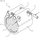
- a pipe connector for connecting a welding joint will now be described with reference to FIGS. 1 and 3 to 8 .
- a pipe connector 1 is a connector that connects two pipes in a non-welding method, and generally includes a casing 2 forming an external shape of the pipe connector, an auxiliary casing 7 installed in a cutout section of the casing 2 of the pipe connector, a clamp member mounted between opposite ends of the casing 2 about the cutout section to allow the casing to contract, wherein the clamp member has clamping bolts 4 to pull the opposite ends towards each other into the cutout section, a rubber sleeve mounted on an inner circumference of the casing, and grip rings 5 conically mounted on opposite inlets of the pipe connector.
- the casing 2 of the pipe connector is formed like a pipe, opposite ends of which are bent inwards to form stopper bends 3 and which has a longitudinal cutout section with a certain width.
- the casing 2 of the pipe connector may be fabricated by bending a metal plate into a cylindrical pipe while leaving a cutout section in the longitudinal direction.
- an outer diameter of the casing 2 may be adjusted to be smaller by adjusting the width of the cutout section.
- the auxiliary casing 7 is provided to cover the longitudinal cutout section of the casing. Like the casing 7, the auxiliary casing also has inwardly bent stopper bends on opposite ends at the same positions as those of the casing 2. One end of the auxiliary casing 7 is fixed to an inner surface of one end of the casing 2.
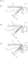
- the grip rings 5 are mounted in three mounting types to clamp outer surfaces of pipes (a straight pipe 20 and a welding joint 21), which are inserted and connected into the inside of the pipe connector 1 in an inclined direction.
- FIG. 3(a) illustrates the mounting of a single grip ring 5
- FIG. 3(b) illustrates the mounting of two overlapped grip rings 5
- FIG. 3(c) illustrates the mounting of one or two grip rings 5 and a support ring 8 provided on a rear side of the grip ring to support the same.
- a thickness "T" of the single grip ring 5 mounted as illustrated in FIG. 3 (a) is selected to be the same as or similar to a thickness "T" of the two overlapped grip rings 5 as illustrated in FIG. 3 (b) . This is because to grip same size pipes requires a same or similar clamping force.
- the single grip ring 5 of FIG. 3 (a) may be made thinner, a reduction in the thickness is not considerable. It is thus assumed that the thickness of the single grip ring illustrated in FIG. 3(a) is substantially the same as that of the two overlapped grip rings 5 illustrated in FIG. 3(b) .
- a thickness "T" of a single grip ring or two-overlapped grip rings 5 mounted as illustrated in FIG. 3(c) is substantially the same as that of the single grip ring of FIG. 3(a) . It is thus noted that the thicknesses of the grip ring(s) illustrated in FIGS. 3(a), 3(b), and 3(c) are assumed to be the same.
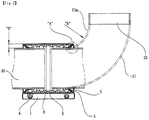
- the pipe connector 1 is characterized by minimized widths "B" of the stopper bends 3 of the pipe connector 1 as illustrated in FIGS. 3 and 5 to allow connection ends of a welding joint 21, such as an elbow joint curved at 90 degrees, to be inserted as deeply as possible into the inside of the pipe connector 1.
- a welding joint 21 such as an elbow joint curved at 90 degrees
- the pipe connector of the present invention is characterized by a projection ring 9 on an inner circumference of the rubber sleeve 6 to allow a bent connection end of a welding joint 21 to be inserted into the inside of the pipe connector 1 in an aligned manner.
- the pipe connector of the present invention is characterized by a spacer member 10 composed of a wire or an iron plate band and mounted between adjacent pipe connectors 1 mounted to the same pipe to allow that pipe to be stably connected by the adjacent pipe connectors 1.
- the grip ring 5 or grip rings 5 illustrated in FIGS. 3(a), 3(b), and 3(c) are assumed to be a single integrated grip ring having a thickness "T".
- the width "B" of the stopper bend 3 is made to have a width as much as 1.2 ⁇ 2 times the thickness T of the grip ring 5.
- the width "B" of the stopper bend 3 is made to have a width as much as 1.2 ⁇ 2 times a total thickness of the grip ring 5 and the support ring 8.
- FIG. 3 is an enlarged view of section "A" of FIG. 2 illustrating the conventional pipe connector, wherein the stopper bends 3 have a wide width.
- the present invention also has a similar configuration about the section "A” to the above conventional configuration, except narrow widths of the stopper bends, so a relevant configuration of the present invention will also be described with reference to FIG. 3 .
- Table 1 Standards (Inner Diameter) of Pipe Connector (mm) Thickness of Grip Ring (mm) Width (B) of Stopper Bend (mm) Related Art Present Invention 15A ⁇ 40A 2.0 5.5 2.4-4.0 50A ⁇ 65A 2.4 6.5 2.88-4.8 80A ⁇ 150A 3.0 8.5 3.6-6.0 200A ⁇ 400A 3.0 10 3.6-6.0
- Table 1 shows configurations of a pipe connector in which grip ring is only mounted as illustrated in FIGS. 3 (a) and 3(b), wherein, in the pipe connector 1 connecting a pipe (including a welding joint) having an outer diameter of 15 mm, a thickness of the grip ring 5 is 2.0 mm, and a width of the stopper bend 3 preferably ranges from 2.4 mm to 4.0 mm, which is as much as from 1.2 to 2 times the thickness of the grip ring 5.
- the stopper bend 3 may have a minimum width of 2.0 mm in order to allow an outer circumference of the grip ring 5 to be held by the stopper bend.
- pipe connectors of standards 15A to 65A are formed from a 1 mm-thickness stainless plate, to form a stopper bend by bending the 1 mm-thickness stainless plate into a bend of 2 mm or less is not desirable in terms of workability and strength. This is the reason why to determine a minimum magnification factor of the thickness of the grip ring to be 1.2 so as to obtain a 2.4 mm minimum width of the stopper bend for the 15 mm pipe connector 1.
- a connection end of a curved welding joint 21 may be sufficiently inserted into the pipe connector while the outer circumference of the grip ring 5 may be sufficiently held by the stopper bend 3, and the casing 2 of the pipe connector may have advantageous strength.
- the present invention has a 2.4 mm ⁇ 4.0 mm width of the stopper bend that is reduced from a 5.5 mm width of a conventional stopper bend by 1.0 mm ⁇ 3.1 mm, leading to a reduction of maximum 56.1 %, thereby allowing the connection end of the curved welding joint 21 to be sufficiently deeply inserted into the pipe connector 1.
- Table 2 shows configurations of the pipe connector in which the grip ring 5 and the support ring 8 are mounted together as illustrated in FIG. 3(c) .
- a total thickness of the grip ring 5 and the support ring 8 is 4.0 mm, so, even when a width of the stopper bend 3 is formed to be 4.8 mm at minimum, the width is greater than the total thickness of 4.0 mm, allowing the grip ring 5 and the support ring 8 to be sufficiently held and supported by the stopper bend.
- the width of the stopper bend 3 is smaller than a 10 mm width of a conventional stopper bend by 2.0 mm.
- the width is reduced from a 30 mm width of a conventional stopper bend by 22.8 mm, allowing a connection end of a curved welding joint 21 to be sufficiently deeply inserted into the pipe connector 1.
- a straight pipe 20 and a welding joint such as a 90° elbow joint, may be stably connected.
- the projection ring 9 is formed on the inner circumference of the rubber sleeve 6 on the side toward which the connection end of the welding joint 21 is inserted to allow the connection end of the welding joint 21 to be held by the projection ring.
- the projection ring 9 is circumferentially formed at a position, which is spaced a distance from one inlet of the pipe connector 1, whereby, in the case in which the welding joint 21 is a 90° elbow joint, a connection end of the welding joint, bent at a right angle, is correctly inserted into the pipe connector.
- the spacer member 10 is mounted between adjacent pipe connectors 1 connecting a straight pipe 20 and a welding joint 21 in order to prevent the adjacent pipe connectors 1 from being separated from each other, thereby maintaining the connection therebetween.
- the spacer member is formed from an iron wire or an iron plate band, and, as illustrated in FIGS. 6 and 7 , the spacer member is mounted to the casing 2 of the pipe connector such that opposite ends thereof are respectively hooked and coupled to opposite clamping bolts 4 mounted to the casing 2.
- FIGS. 8(a) and 8(b) illustrate another embodiment of a spacer member 10.
- the spacer member 10 is configured to include a screw pipe 12 having an internal screw part on an inner circumference thereof, screws 12 respectively screwed through opposite sides of the screw pipe via brackets 13 so that heads of the screws are abutted against the brackets, and wire parts 11 respectively provided on opposite outer sides of the brackets, wherein the wire part has hook portions 11a on opposite outer ends thereof.
- the spacer member 10 is further provided with another screw 14a that is vertically fastened through the screw pipe 12 via another bracket against which a head of the screw 14a is abutted.
- Wire parts 11 are respectively connected to outer ends of the brackets 13.
- the wire part is provided with hook portions 11a on opposite outer ends thereof.
- the wire part 11 of the spacer member 10 illustrated in FIGS. 6 to 8 is formed from a flexible iron wire
- the wire part may be formed from an iron plate band.
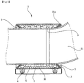
- ends of the straight pipe 20 and the welding joint 21 or 22 are inserted into the rubber sleeve 6 as described above, ends of the straight pipe 20 and the welding joint 21 or 22 are respectively inserted into opposite sides of the pipe connector 1 such that the ends of the straight pipe 20 and the welding joint 21 or 22 come into contact with the projection ring 9 formed on the inner circumference of the rubber sleeve 6.
- the projection ring 9 is formed on the inner circumference of the rubber sleeve 6 to protrude inwards perpendicularly to the outer circumference of the casing 2 of the pipe connector, when oppositely closely abutted against the projection ring 9, the ends of the straight pipe 20 and the welding joint 21 or 22 are inserted into the pipe connector along the same center line.
- the ends of the straight pipe 20 and the welding joint 21 or 22 are respectively connected along the same center line.
- the welding joint 21 since the end of the welding joint 21 or 22, an insertion depth of which is not deeper than that of the straight pipe 20, is inserted in an aligned state, the welding joint 21 can be firmly secured by correctly fastening the outer circumference of the end of the welding joint. Accordingly, the straight pipe 20 and the welding joint 21 or 22 can be stably connected.
- the width of the stopper bend 3 is made smaller than the related art.
- an inwardly curved part 21a of the connection end of the welding joint 21 or 22 is subjected to less interference from the stopper bend by a reduction in the width of the stopper bend.
- the connection end can be inserted deeper into the pipe connector 1 while maintaining the welding joint at a right angle relative to the pipe connector.
- connection end of the welding joint 21 or 22 With the configuration to allow the connection end of the welding joint 21 or 22 to be inserted deeper into the pipe connector 1, when the connection ends of the straight pipe 20 and the welding joint 21 or 22 are respectively connected by the clamping bolts 4 in a state in which the connection end of the welding joint is inserted deeper, a clamping area of the connection end increases, thereby allowing the connection end of the welding joint 21 or 22 to be firmly clamped. Subsequently, a description will be made of the mounting of the spacer member 10, which is mounted between adjacent pipe connectors 1 that are mounted to a set of pipes, i.e. a straight pipe 20 and a welding joint 21 or 22, to connect the straight pipe and the welding joint, as illustrated in FIGS. 6 to 8 .
- the spacer member 10 is thus provided to connect the adjacent pipe connectors mounted to the set of the pipe and the welding joint in order to prevent the welding joint 21 or 22 from being decoupled from the pipe connectors 1.
- FIG. 6 illustrates the case in which a spacer member 10, which is formed from an iron plate band, an iron wire, or a wire rope, is connected between adjacent pipe connectors 1.
- a spacer member 10 which is formed from an iron plate band, an iron wire, or a wire rope, is connected between adjacent pipe connectors 1.
- the spacer member 10 is mounted as tight as possible.
- FIGS. 7 and 8 illustrate another embodiment of the spacer member 10, which further includes a tensioner at a middle portion of the spacer member connecting the adjacent pipe connectors 1 in order to regulate tension so that the spacer member 10 can be maintained to be continuously tightened.
- the spacer member 10 regulates tensions of opposite wire parts 11 with the same operative principle as in a known turnbuckle.
- the spacer member 10 illustrated in FIGS. 7(a) and 8(a) is connected between pipe connectors 1 connected to opposite connection ends of a 90° elbow joint 21 such that respective hook portions 11a thereof are connected to certain portions of the pipe connectors 1.
- the tension of the spacer member 10 can be regulated according to the direction in which the screws are screwed.
- the spacer member 10 illustrated in FIGS. 7(b) and 8(b) is connected between three pipe connectors 1 mounted to three connection ends of a tee-type welding joint 22.
- the three connection ends include two horizontal connection ends and one vertical connection end perpendicular thereto.
- a horizontal component of the spacer member is first connected between the pipe connectors 1 respectively mounted to the set of horizontal connection, and then is tensioned by screwing the opposite screws 14.
- the present invention is applicable to a variety of industrial fields adopting a pipe connector for connecting a welding joint, such as a 90° elbow joint or a tee, and a straight pipe.
Landscapes
- Engineering & Computer Science (AREA)
- General Engineering & Computer Science (AREA)
- Mechanical Engineering (AREA)
- Physics & Mathematics (AREA)
- Fluid Mechanics (AREA)
- Joints With Sleeves (AREA)
Applications Claiming Priority (2)
| Application Number | Priority Date | Filing Date | Title |
|---|---|---|---|
| KR1020130107068A KR101403531B1 (ko) | 2013-07-30 | 2013-09-06 | 용접이음쇠 연결용 관연결구 |
| PCT/KR2014/008279 WO2015034267A1 (fr) | 2013-09-06 | 2014-09-03 | Raccord de conduite permettant de raccorder un joint de soudure |
Publications (2)
| Publication Number | Publication Date |
|---|---|
| EP3043100A1 true EP3043100A1 (fr) | 2016-07-13 |
| EP3043100A4 EP3043100A4 (fr) | 2016-09-21 |
Family
ID=52629319
Family Applications (1)
| Application Number | Title | Priority Date | Filing Date |
|---|---|---|---|
| EP14842051.6A Withdrawn EP3043100A4 (fr) | 2013-09-06 | 2014-09-03 | Raccord de conduite permettant de raccorder un joint de soudure |
Country Status (4)
| Country | Link |
|---|---|
| EP (1) | EP3043100A4 (fr) |
| JP (1) | JP5994039B1 (fr) |
| CN (1) | CN105518367A (fr) |
| WO (1) | WO2015034267A1 (fr) |
Cited By (1)
| Publication number | Priority date | Publication date | Assignee | Title |
|---|---|---|---|---|
| CN106438489A (zh) * | 2016-12-14 | 2017-02-22 | 宜兴市灵谷塑料设备有限公司 | 水泵出口连接密封装置 |
Families Citing this family (6)
| Publication number | Priority date | Publication date | Assignee | Title |
|---|---|---|---|---|
| ITUB20152332A1 (it) * | 2015-07-21 | 2017-01-21 | Saipem Spa | Dispositivo di giunzione di una condotta per cambi di pendenza di fondali, condotta continua comprendente detto dispositivo e metodo di giunzione |
| GB2550933B (en) * | 2016-06-01 | 2019-01-16 | Taylor Kerr Couplings Ltd | Self-aligning pipe coupling |
| DE102016115536A1 (de) | 2016-08-22 | 2018-02-22 | Norma Germany Gmbh | Sicherungskralle |
| CN107816585B (zh) * | 2017-10-26 | 2024-04-16 | 中国石油集团渤海石油装备制造有限公司 | 一种大口径钢管与玻璃钢管的连接装置 |
| GB2577334B (en) * | 2018-09-24 | 2020-12-23 | Taylor Kerr Couplings Ltd | Pipe coupling with improved tensioning system |
| CN115533442A (zh) * | 2022-11-10 | 2022-12-30 | 中国十九冶集团有限公司 | 联络管组焊固定装置 |
Family Cites Families (11)
| Publication number | Priority date | Publication date | Assignee | Title |
|---|---|---|---|---|
| AT353561B (de) * | 1976-07-21 | 1979-11-26 | Straub Immanuel | Rohrkupplung |
| FI75040C (sv) * | 1987-01-30 | 1988-04-11 | Goeran Sundholm | Svetsad rörförbindning. |
| CH676875A5 (en) * | 1988-09-28 | 1991-03-15 | Immanuel Straub | Clamping sleeve for joining tow pipe ends - has contractible clamping rings surrounded firmly by sleeve housing |
| DE19802676C1 (de) * | 1998-01-24 | 1999-05-06 | Rasmussen Gmbh | Spannbare Rohrkupplung |
| JP2001032976A (ja) * | 1999-07-22 | 2001-02-06 | Shigeru Akagaki | 管の連結具 |
| JP3797534B2 (ja) * | 2000-02-18 | 2006-07-19 | 川口工業株式会社 | 管体の連結構造 |
| JP2001289322A (ja) * | 2000-04-03 | 2001-10-19 | Bantekku Kk | 管体の連結構造 |
| KR200363185Y1 (ko) | 2004-07-01 | 2004-09-24 | (주) 정우카프링 | 배관용 연결구 |
| JP2007225094A (ja) * | 2006-02-27 | 2007-09-06 | Hitachi Metals Ltd | カップリング型継手 |
| KR200454571Y1 (ko) * | 2009-11-27 | 2011-07-12 | (주) 정우카프링 | 배관용 연결구 |
| KR101328191B1 (ko) * | 2011-03-11 | 2013-11-13 | 이무노 | 관 연결구 |
-
2014
- 2014-09-03 EP EP14842051.6A patent/EP3043100A4/fr not_active Withdrawn
- 2014-09-03 JP JP2016516037A patent/JP5994039B1/ja active Active
- 2014-09-03 CN CN201480048960.3A patent/CN105518367A/zh active Pending
- 2014-09-03 WO PCT/KR2014/008279 patent/WO2015034267A1/fr not_active Ceased
Cited By (1)
| Publication number | Priority date | Publication date | Assignee | Title |
|---|---|---|---|---|
| CN106438489A (zh) * | 2016-12-14 | 2017-02-22 | 宜兴市灵谷塑料设备有限公司 | 水泵出口连接密封装置 |
Also Published As
| Publication number | Publication date |
|---|---|
| JP5994039B1 (ja) | 2016-09-21 |
| WO2015034267A1 (fr) | 2015-03-12 |
| EP3043100A4 (fr) | 2016-09-21 |
| JP2016532825A (ja) | 2016-10-20 |
| CN105518367A (zh) | 2016-04-20 |
Similar Documents
| Publication | Publication Date | Title |
|---|---|---|
| EP3043100A1 (fr) | Raccord de conduite permettant de raccorder un joint de soudure | |
| EP2241766B1 (fr) | Collier de serrage | |
| KR20100127764A (ko) | 개스킷을 구비한 중앙 리브를 가진 단일 볼트 밴드 클램프 및 이 밴드 클램프를 사용한 겹치기 이음매 | |
| JP5006216B2 (ja) | Tボルトクランプのクイックアタッチラッチ | |
| JP5391273B2 (ja) | ホースクランプ | |
| AU2008229788B2 (en) | Pipe clamp | |
| CN112567162B (zh) | 用于夹具组合件的止动器 | |
| KR20160019930A (ko) | 파이프 클램프 | |
| TW201506290A (zh) | 耳式夾具 | |
| KR20210131531A (ko) | 개량된 커플링장치 | |
| US6655642B1 (en) | Single piece machined strap clamp | |
| KR101064847B1 (ko) | 호스 체결용 클램프의 지지구조체 | |
| KR20140049653A (ko) | 배관 연결장치 | |
| KR20130122710A (ko) | 조글을 갖는 클램프 | |
| KR20190130016A (ko) | 파이프 커플링 | |
| EP2066955A2 (fr) | Collier de serrage à boucle intérieure | |
| KR101205699B1 (ko) | 벨로우즈 대용 지그 | |
| KR101403531B1 (ko) | 용접이음쇠 연결용 관연결구 | |
| KR20130006352U (ko) | 엘보우 단관파이프용 고정지그 | |
| KR102574611B1 (ko) | 유니버설 클램핑 장치 | |
| JP4056736B2 (ja) | 管継手 | |
| NO337683B1 (no) | Klemme for høytrykksslanger | |
| US20180216774A1 (en) | Clamping system | |
| CN218494440U (zh) | 抱箍装置 | |
| CN223164798U (zh) | 一种防变形卡箍 |
Legal Events
| Date | Code | Title | Description |
|---|---|---|---|
| PUAI | Public reference made under article 153(3) epc to a published international application that has entered the european phase |
Free format text: ORIGINAL CODE: 0009012 |
|
| 17P | Request for examination filed |
Effective date: 20160314 |
|
| AK | Designated contracting states |
Kind code of ref document: A1 Designated state(s): AL AT BE BG CH CY CZ DE DK EE ES FI FR GB GR HR HU IE IS IT LI LT LU LV MC MK MT NL NO PL PT RO RS SE SI SK SM TR |
|
| AX | Request for extension of the european patent |
Extension state: BA ME |
|
| A4 | Supplementary search report drawn up and despatched |
Effective date: 20160819 |
|
| RIC1 | Information provided on ipc code assigned before grant |
Ipc: F16L 21/08 20060101AFI20160812BHEP Ipc: F16L 17/04 20060101ALI20160812BHEP Ipc: F16L 13/02 20060101ALI20160812BHEP Ipc: F16L 41/06 20060101ALI20160812BHEP |
|
| DAX | Request for extension of the european patent (deleted) | ||
| STAA | Information on the status of an ep patent application or granted ep patent |
Free format text: STATUS: THE APPLICATION IS DEEMED TO BE WITHDRAWN |
|
| 18D | Application deemed to be withdrawn |
Effective date: 20170317 |