EP3043189B1 - Optisches system zur identifikation von störungen in gemischten hochspannungsübertragungsleitungen - Google Patents
Optisches system zur identifikation von störungen in gemischten hochspannungsübertragungsleitungen Download PDFInfo
- Publication number
- EP3043189B1 EP3043189B1 EP13799624.5A EP13799624A EP3043189B1 EP 3043189 B1 EP3043189 B1 EP 3043189B1 EP 13799624 A EP13799624 A EP 13799624A EP 3043189 B1 EP3043189 B1 EP 3043189B1
- Authority
- EP
- European Patent Office
- Prior art keywords
- optical
- fiber
- current
- sensor
- optical fiber
- Prior art date
- Legal status (The legal status is an assumption and is not a legal conclusion. Google has not performed a legal analysis and makes no representation as to the accuracy of the status listed.)
- Active
Links
Images






Classifications
-
- G—PHYSICS
- G01—MEASURING; TESTING
- G01R—MEASURING ELECTRIC VARIABLES; MEASURING MAGNETIC VARIABLES
- G01R33/00—Arrangements or instruments for measuring magnetic variables
- G01R33/02—Measuring direction or magnitude of magnetic fields or magnetic flux
- G01R33/032—Measuring direction or magnitude of magnetic fields or magnetic flux using magneto-optic devices, e.g. Faraday or Cotton-Mouton effect
-
- G—PHYSICS
- G01—MEASURING; TESTING
- G01R—MEASURING ELECTRIC VARIABLES; MEASURING MAGNETIC VARIABLES
- G01R15/00—Details of measuring arrangements of the types provided for in groups G01R17/00 - G01R29/00, G01R33/00 - G01R33/26 or G01R35/00
- G01R15/14—Adaptations providing voltage or current isolation, e.g. for high-voltage or high-current networks
- G01R15/24—Adaptations providing voltage or current isolation, e.g. for high-voltage or high-current networks using light-modulating devices
- G01R15/245—Adaptations providing voltage or current isolation, e.g. for high-voltage or high-current networks using light-modulating devices using magneto-optical modulators, e.g. based on the Faraday or Cotton-Mouton effect
- G01R15/246—Adaptations providing voltage or current isolation, e.g. for high-voltage or high-current networks using light-modulating devices using magneto-optical modulators, e.g. based on the Faraday or Cotton-Mouton effect based on the Faraday, i.e. linear magneto-optic, effect
-
- G—PHYSICS
- G01—MEASURING; TESTING
- G01R—MEASURING ELECTRIC VARIABLES; MEASURING MAGNETIC VARIABLES
- G01R15/00—Details of measuring arrangements of the types provided for in groups G01R17/00 - G01R29/00, G01R33/00 - G01R33/26 or G01R35/00
- G01R15/14—Adaptations providing voltage or current isolation, e.g. for high-voltage or high-current networks
- G01R15/146—Measuring arrangements for current not covered by other subgroups of G01R15/14, e.g. using current dividers, shunts, or measuring a voltage drop
Definitions
- the invention relates to the field of fault identification in electrical power transmission lines and, in particular, to the identification of faults in mixed lines, in other words, those that combine overhead sections (also called aerial sections ) with sections in cable.
- the fault can be interpreted as being foreseeably permanent, meaning that maintenance operatives must be dispatched to solve it. This is the usual functioning when a fault occurs on an overhead line.
- re-engagement is one of the main functions incorporated into the protections for overhead high voltage lines, since it makes it possible to continue with an overhead line in service following a temporary fault occurring on it.
- electrical power distribution lines comprise some non-overhead section, in other words, some section in cable (the power transmission line is clad with insulation).
- the most frequent examples (although not the only ones) of electrical power distribution sections in cable are underground sections (for example, in proximity to an airport or urban zones or for environmental reasons) and underwater sections.
- underground sections for example, in proximity to an airport or urban zones or for environmental reasons
- underwater sections for example, because the fault may be due to operatives or machines working, in which case it could put the operatives' lives at risk.
- the section is underground, the re-engagement function is overridden, because faults in underground portions are considered to be permanent.
- the problem lies in the fact that the fault may have occurred in the overhead section of the line, but in this case automatic re-engagement cannot be performed in the event the fault is in the underground section (in general, the section in cable).
- the problem therefore arises in mixed lines (having overhead sections and cable sections), where it is very important to be able to determine in which section or at which point the fault occurs.
- An error in detection declaring the temporary fault to be in the underground section when in reality the fault is in the overhead section, unnecessarily deprives the power system from continuing to operate with the mixed line in service. Therefore, one objective of electrical power grid providers is to identify or distinguish the cable section of the mixed line where the fault occurs, in order to be able to use re-engagement in all the existing overhead sections and to increase availability.
- Differential protection is widely implemented as a unitary protection in transport grids (lines, transformers, busbars) and certain distribution systems. It is based on the calculation of the difference in current that "enters” and “leaves” the protected element. This difference is practically zero in normal conditions and with external faults, whereas for internal faults it is other than zero.
- This entails installing a current transformer before the start of the cable section (underground, for example) and another current transformer at the exit of the cable section and the corresponding protection equipment provided with synchronisation and communications in order to compare the measurements of both transformers. If the currents are not the same, it means that a fault has occurred in the underground section.
- line differential protections are installed on both ends of the line, with communication between them, to know the current measured by each one of them. Based on the local current measurement and the measurement received through communication from the remote end, each protection calculates the differential current and determines how to act according to an operating characteristic.
- OCS optical current sensors
- the lines carry a cable that runs along the top part of the electricity pylons, which is used as a lightning arrestor.
- This cable has a hollow steel core and inside can carry a series of optical fiber cables (known as OPGW, Optical Ground Wire ). Therefore, some of these cables can be used to transmit signals from the OCS.
- OPGW optical fiber cables
- Optical Ground Wire Optical Ground Wire
- the problem is considered as to how to reduce the number of optical fiber cables required to transmit the signals from the OCS.
- This can be achieved by means of the optical time-division multiplexing technique, as described, for example, in patent documents US2004/0189997A1 , US6611337 and WO2009/103126A1
- the optical sensors take specific current measurements at a same instant in each phase, and by means of a multiplexed network with delays, a series of pulses that are out of phase in time is obtained. In this way, it is possible to know the information with a reduced number of optical fiber cables (the number of optical fibers required may be one, two, three, four, six or twelve).
- the usual optical sensors installed on the line have a high cost.
- a flexible sensor which is a sensitive optical fiber cable which is wound around the conductor, thereby constituting the optical sensor, as explained below.
- the remote current measurement using passive optical sensors helps to overcome the problems associated to electromagnetic current transformers, such as nonlinearities and saturations, in addition to the problems associated to their complex installation in places where it is not desirable to modify the existing installation.
- sensors are based on the Faraday effect, whose functioning principle consists of measuring the change in the state of light polarisation in a magneto-optical material, when the latter is subjected to a magnetic field.
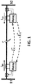
- the state of polarisation of the light when it passes through a magneto-optical material 10 subjected to a magnetic field H sustains a variation proportional to the current in the same direction of light propagation (incident beam 11 and transmitted light 12).
- said magneto-optical material 10 surrounds a conductor, the measurement of the change in state of polarisation throughout the entire material indicates the current that is circulating through said conductor.
- Figure 2B shows the beginning of a Faraday effect optical current sensor, made up of a sensor fiber 25 which surrounds a conductor 24, a source of light 21 which emits an optical signal, an optical circuit 23 to which the two ends of the sensor fiber 25 are connected, a detector 22 and a signal processing block 20.
- the sensor's response to the magnetic field is totally linear, and therefore all sources of error implicit in electromagnetic circuits disappear.
- the disappearance of all nonlinearities associated to the phenomena of ferromagnetic core saturation is particularly important.
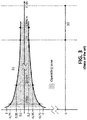
- the graph of figure 3 shows the precision of an optical current measurement transformer. As may be seen, as the current increases the shaded zone of transformer operation narrows. This allows the same unit to comply with the measurement and protection classes, with the particular feature of having measurement precision (the curve represents the measurement precision limit 31) in the protection range (the figure illustrates the conventional protection precision limit 32).
- the present invention tries to resolve the drawbacks mentioned above by means of an optical differential protection system for the remote identification of faults on mixed electrical power transmission lines (in other words, having at least one section of the line in cable, for example underground or underwater), which does not require carrying a power supply to any of the sensors.
- a differential optical system for the remote identification of faults on a mixed electrical power transmission line delimited by a first electrical substation and a second electrical substation, wherein said mixed line comprises at least one section of overhead line (aerial line) and one section of cabled line.
- the system comprises at least one first optical current sensor situated at a first point of the mixed line, which comprises: a sensor fiber designed to surround an electrical power transmission cable whose intensity is to be monitored, and one passive optical circuit; and at least one second current measurement device independent of the first optical current sensor, situated at a second point of the mixed line, configured to take measurements of the current intensity that circulates through an electrical transmission cable.
- the sensor fiber is made up of a section of sensitive optical fiber connected at one end to the passive optical circuit and of one section of insensitive optical fiber (or non-sensitive optical fiber) connected at one end to the passive optical circuit, and the free end of the sensitive optical fiber is connected by means of a splice to the free end of the insensitive optical fiber, in such a way that the section of sensitive optical fiber acts as the element for measuring the current intensity to be monitored and the section of insensitive optical fiber acts as the means of transmission of the measurements taken towards the passive optical circuit.
- the differential optical system comprises additionally a fault discrimination device configured to process the current measurements coming from the at least one first optical current sensor and from the at least one second current measurement device and to detect faults in the mixed electrical power transmission line. This device is connected to the optical current sensor by means of single-mode optical fiber configured for sending an optical signal and returning the measurements taken by the sensor fiber to the fault discrimination device.
- the at least one second current measurement device independent of the first optical current sensor is a second optical current sensor, which comprises: one sensor fiber which can be disposed surrounding an electrical power transmission cable whose intensity is to be monitored, and one passive optical circuit.
- the at least one second current measurement device independent of the first optical current sensor can be a current transformer.
- the fault discrimination device is preferably situated in the electrical substation nearest to the second current measurement device.
- the passive optical circuit comprises a first bidirectional coupler; three second bidirectional couplers connected to the first bidirectional coupler; and two third bidirectional couplers connected respectively to one of the ports of each second bidirectional coupler; and where the sensor fiber is connected to the first bidirectional coupler forming a Sagnac loop, in such a way that in response to a pulse of light sent to the sensor fiber, the latter sends a plurality of current measurements taken in each phase and at several different instances in time.
- the sensor fiber comprises a high birefringence sensitive optical fiber. And more preferably, the high birefringence sensitive optical fiber has been twisted during its manufacture.
- connection of one end of the sensitive optical fiber to the passive optical circuit, and the connection of one end of the insensitive optical fiber to the passive optical circuit, as well as the splice between the free ends of the sensitive optical fiber and the insensitive optical fiber, are performed at the factory.
- the optical current sensor is designed to be installed around an insulated high voltage cable.
- the fault discrimination device is designed to be installed in a substation of the electrical power grid.
- At least at the first point of the mixed line there is preferably a plurality of optical current sensors each one made up of one coiled sensor fiber configured to surround an electrical power transmission cable whose intensity is to be monitored, and one passive optical circuit; and one junction box to which the plurality of optical current sensors are connected using dedicated fiber optic cable.
- the fault discrimination device is connected to the junction box using single-mode optical fiber.
- the junction box is designed to be installed on a pylon that carries the electrical power transmission line.
- multiplexing means are included configured to multiplex each output fiber of each passive optical circuit into a single multiplexed signal connected to the junction box.
- the fault discrimination device comprises a source of light configured to emit a pulse of light towards the sensor fiber; a plurality of photodetectors configured to receive the responses coming from the sensor fiber; and means for processing the responses and detecting faults in the electrical power transmission line.
- the fault discrimination device comprises also a plurality of duplex ports of single-mode optical fiber.
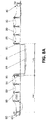
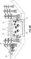
- Figure 8A shows an outline of the differential system of fault identification in mixed transmission lines of the present invention.
- a part of the electrical power grid is illustrated with various overhead (aerial) electrical power distribution lines (specifically, eight pylons are shown).
- the pylons (towers) carry high voltage lines overhead 83.
- a fault discrimination terminal 80 is shown, which is described in more detail in relation to figure 7 , installed in a substation ES.
- the figure also shows the single-mode optical fiber 89 that runs throughout the installation end to end (between the two substations 81 86).
- the remote optical current sensors are designed to be installed around an insulated high voltage cable.
- the optical current sensors 85 are installed on each one of the two pylons that limit the underground section 84.
- the system is made up of several optical current sensors (for example, six), several dedicated optical fibers, preferably single-mode optical fiber 89 (for example standard OPGW single-mode optical fiber) and one fault detection and discrimination terminal.
- three optical current sensors 85 are installed on each one of the two towers that limit the underground section 84 (one per phase).
- the sensors are grouped preferably into threes so as to minimise the number of dedicated optical fibers to be used and are connected in a connections box or junction box 82. In a possible embodiment, the multiplexing of the sensors is performed in this box.
- the underground section measures approximately 1 km and the distance between the fault discrimination terminal 80 and the first pylon that delimits the underground section is of approximately 6 km.
- This data is by way of an example and may change in the various real implementations, depending on the disposition of the lines, pylons, etc.
- Each set of three optical current sensors 85 installed on each pylon that delimits the underground section 84 is made up of totally passive optical sensors. These two sets of passive optical sensors allow differential optical measurements to be taken for the remote identification of faults in the underground section. Unlike the systems for taking differential measurements based on conventional optical sensors, the one of the invention, due to the fact that it is totally passive, does not require an electrical power supply to be taken to any of the sensors. In other words, the sensor(s) located at one point of the mixed line is (are) independent of the sensor(s) located at another point of the mixed line.
- each set of three sensors 85 performs the corresponding measurements in a totally passive manner, and sends them to the fault discrimination terminal 80.
- the sensors 85 of each pylon that delimits the underground section 84 are independent of each other, unlike, for example, the master sensor and the slave sensor of the differential optical system of WO2011/031945A1 .
- the mixed line may be intermediate or terminal. It is intermediate when the section of cable (underground, underwater, etc.) runs between two overhead sections.
- the fault discrimination terminal 80 is installed in a remote substation ES in respect to any of the two pylons that delimit the section of cable.
- the mixed line is terminal when the section of cable is followed by an overhead section at one end only.
- the fault discrimination terminal 80 is installed in a remote substation ES at the place (or nearby) that delimits the start of the section of cable (for example, underground).
- the electrical current measurement can be taken locally, for example using a current transformer.
- the measurement is taken locally (as opposed to remotely) because the measurement device (for example, current transformer) is located at the end of the section of cabled line where the fault discrimination device 80 is also located.
- the latter is located preferably in the electricity substation (in figure 8D , referred to as ES-1) nearest to said current measurement device.
- the measurement device for example, current transformer
- ES-1 electricity substation
- Figure 8B shows in detail an outline of an intermediate mixed line.
- the figure shows the two pylons that delimit the underground section, the high voltage lines that run overhead 83 and underground 84, the single-mode optical fiber 89 (for example, OPGW), the fault discrimination terminal 80 and the junction boxes 82.
- the single-mode optical fiber 89 for example, OPGW
- Figure 8C shows a detail of an intermediate mixed line, wherein 6 optical current sensors and two pairs of single-mode fiber 89 (for example OPGW) are used.
- Figure 8D shows a detail of a terminal mixed line, wherein 3 optical current sensors are used at the end of the remote underground section (in other words, on a pylon of the overhead section) in respect to the substation that has the fault discrimination terminal 80 and a single-mode fiber pair 89 (for example OPGW) installed.
- a single-mode fiber pair 89 for example OPGW
- the differential measurement is made up of electrical current measurements taken remotely using the optical current sensors and electrical current measurements taken locally without having to use the passive optical network.
- the differential measurement of the electrical current is based on taking measurements of said current at two different points of the section under inspection and comparing (in the fault discrimination device) the measurements between the two points.
- the remote measurements are sent to said fault discrimination device through optical fiber.
- the two points at which the measurements are taken may be several kilometres apart. If a fault occurs between the two sensitive devices, the currents that pass through the two measurement points are different and that difference is detected in the fault discrimination device.
- the current sensors 85 are installed preferably below the terminal bushings, embracing both the conductor as well as the bushing connection to earth.
- the junction box 86 and the sensor fiber (of the current sensors 85) as well as the single-mode interconnection fiber (for example, OPGW) are secured to the metallic structure of the frame using standardised supports. No alteration of the frame is required.
- the optical circuit box is secured trying to minimise the distance between it and the measurement point. This distance is preferably less than 1 m.
- the sensor fiber of the current sensor 85 is wound around the circuit to be measured (cable and earth return of the bushing). The end of the sensor fiber is secured in the optical circuit box using hardware incorporated thereto. To avoid mechanical fatigue on the sensor, once wound it is secured with staples supplied to the metal openwork structure.
- One single hose with 2 single-mode fibers is run up to the junction box of the OPGW.
- the 2 fibers from the current sensors are fused to two fibers of the OPGW.
- After checking the losses of the optical link one proceeds with connecting in the substation said fibers to the corresponding optical channel of the fault discrimination terminal or module.
- Figure 4A shows a preferred embodiment of the passive optical circuit of the current sensor 40, used to take remote optical measurements of the electrical voltage in the mixed section.
- the current sensor 40 is totally passive, in other words, it does not require an electrical power supply. This makes it possible to perform remote current measurements, eliminating any type of infrastructure at the measurement point.
- the current sensor 40 comprises a Sagnac interferometer closed by a bidirectional coupler C3.
- the interferometer has three external ports E1 E2 E3 and three internal ones, two of which close the Sagnac loop I1 13.
- the coupler C3 is therefore a 3x3 coupler. This eliminates the need to use modulators or other elements that require control electronics.
- Couplers C4 C5 C6 are of the 2 x 2 type, in other words, are capable of coupling two inputs to two outputs in a bidirectional manner. In the implementation of the figure, one of the outputs is left unconnected, with the couplers acting in 2 x 1 mode in a bidirectional manner. At the same time, couplers C4 C5 C6 are connected to bidirectional couplers C1 C2 which in this configuration are of type 1 x 3, in other words, couple one input to three outputs and vice versa.
- the output of the optical source 42 after travelling through a standard single-mode fiber (for example OPGW) 44, reaches the coupler C1 and from there is immediately coupled (without intended delay) to coupler C6 and after a delay imposed by the delay loop 46 1 to coupler C4, and following another delay imposed by the delay loop 46 2 to coupler C5.
- the two delays 46 1 46 2 are different to each other.
- C1 and C5 and C1 and C6 a depolariser 47 1 47 2 47 3 is included.
- the output of coupler C4 is carried immediately (without intended delay) to coupler C3. The same happens with the outputs of couplers C5 and C6.
- Each pulse of light that enters C3 produces 3 output pulses, for each one of its ports E1 E2 E3. As 3 pulses are introduced, 9 output pulses are obtained.
- the delays are calculated taking into account the duration of the pulse of light, and in such a way that the nine outputs do not overlap, and make up a train of 9 pulses for each measurement of one phase.
- Couplers C4 C5 C6 On the return path, the output signals of coupler C3 are directed immediately (without intended delay) to couplers C4 C5 C6. From coupler C6 the signal is coupled immediately to coupler C2. From coupler C5 the signal is coupled to coupler C2 after a delay imposed by delay loop 46 4 . From coupler C4 the signal is coupled to coupler C2 following a delay imposed by delay loop 46 3 . From coupler C2 the nine signals received are sent to detector 43 through a standard single-mode optical fiber (for example OPGW) 45.
- Reference number 48 refers to the passive optical circuit that is made up of the optical current sensor 40 (also made up of the sensor fiber 41, which is explained further below). All the fiber of the passive optical circuit 48 is preferably single-mode fiber.
- the optical sensors take specific current intensity measurements at the same instant in each phase, in such a way that a series of pulses that are out of phase in time are obtained. These measurements are multiplexed and return to the control system (not illustrated in figure 4A ).
- the functioning is as follows: the control system delivers a pulse of light (through emitter 42) to the sensor fiber 41 and this latter returns nine pulses (three measurements in three instances).
- the current intensity value is coded in the relationship between these pulses, in other words, relative, not absolute values are measured.
- Each sensor fiber corresponds to one sensor.
- a sensor is installed on each phase.
- the measurement of each phase generates 9 pulses of light. Therefore for three phases there are 27 pulses of light.
- the measurements of the current in the 3 phases and at the two ends of the cable represent a total of 54 pulses.
- the simplest scheme would entail, in the absence of multiplexing:
- the return signals would not be multiplexed, meaning that 4 fibers would be necessary per sensor: 1 fiber for the pulse to reach from 42, and 3 fibers for the return of the 3 outputs of 3x3 coupler C3.
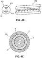
- Figure 4B shows one possible transversal section (left) and one longitudinal section (right) of the sensor fiber 451 used in an embodiment of the present invention.
- the transversal section is illustrated by way of an example, and may adopt other different forms.
- the sensor comprises a high birefringence optical fiber 451 which has been twisted during manufacture.
- the traditional alternative was to use monolithic crystals. In order to allow current primaries to pass through, these crystals had to be built in large dimensions, with the associated problems of fragility and limited flexibility for different sensor designs. For this reason, this optical fiber is used as a sensor element, given that it provides great versatility in the design of electrical current sensors.
- FIG 4C shows a section of a cable (set of the fiber or fibers, together with their cladding and other protective elements) of the flexible sensor according to one implementation of the invention.
- the black dots represent a plurality of sensitive optical fibers 451, which have an approximate diameter of 0.125 mm. Cable is the name given to the set of fiber or fibers, together with their cladding and other protective elements.
- the outer cladding A covers a set of reinforced glass fibers B, which in turn cover a central tube with gel D. Between the central tube with gel D and the reinforced glass fibers B there is a breakaway wire C. Inside the central tube with gel D are the sensor optical fibers 451.
- the proposal is to use sensitive optical fiber 551 connected at the factory to one of the ends 581 of the passive optical circuit 58.
- the length of this sensitive optical fiber is chosen according to the need in each case: it is possible to manufacture current sensors of different sensitivities by merely varying the number of twists of the sensor fiber.
- the other end 582 of the passive optical circuit 58 is connected, also at the factory, to an insensitive optical fiber 561. This prevents having to make delicate connections that operatives may not be prepared for in the field and in conditions of difficult access.
- the sensitive optical fiber part is the one that measures the change in the state of light polarisation in the magneto-optical material when this latter is subjected to a magnetic field. Given that the magneto-optical material (the section of sensitive fiber) surrounds the conductor, the measurement in the change of state of polarisation throughout the entire material indicates the current that is circulating through said conductor.
- the spliced end E which closes the loop made up of the two fibers 551 561 is secured (not with an electrical connection, instead just mechanically secured) next to a point 581 to close the last coil.
- End E can be secured to the passive optical circuit 58 or to any other thing, as long as the sensitive fiber does not unwind and the coil remains closed.
- the sensors based on optical fiber have great mechanical flexibility. Therefore, it is possible to manufacture flexible sensors.
- the sensor element is optical fiber 451 551
- connection of the sensor 40 to the electro-optics 42 43 is performed using single-mode optical fiber 44 45, which may be connectorised, and which can reach distances of more than 10 km, with the only limitation being the one given with the balance of losses.
- the sensors 40 are grouped in threes in order to minimise the number of dedicated optical fibers to be used by the system.
- FIGS 6A and 6B show a particular example of implementation of the invention, with a set of three flexible current sensors and their connection.
- three optical sensors 60 are shown, each one of which is made up of one sensor fiber 61 which act as a magneto-optical element surrounding the cable whose current intensity is to be monitored.
- Each sensor 60 also has its own associated totally passive optical circuit 68a 68b 68c, which must be installed as close as possible to the measurement points.
- Each set of three sensors is connected to a junction box 62.
- This junction box 62 is the one already existing on the transition post from overhead line to cable (for example, underground or underwater).
- the optical fibers run through OPGW 64.
- the fibers run through a cable that is buried next to the electrical conductors. This is why a junction box 62 is necessary, in order to pass from one type of cable to another.
- the system of the invention takes advantage of this circumstance in order to be able to access the optical fibers that run from one substation to another in a simple manner.
- the junction box 62 receives three cables (each one of which has several optical fibers): one is the single-mode fiber cable OPGW 64 which runs next to the overhead line up to the substation; another one 66 is the one that runs next to the underground cable towards the other substation, which is the continuation of the single-mode OPGW fiber (all the fibers are fused); the third cable 67 is the one coming from the system of sensors, which is normally composed of 1 or 2 or 6 fibers. In the junction box 62 it is necessary to "break" the fusions of the fibers that run from one substation to another and that are intended for use, and to fuse them to the fibers of the measurement system of the invention.
- the choice to use the fibers that come from the OPGW or from the underground part depends only on which substation the sensors need to be connected to.
- the optical circuits 68a 68b 68c can be connected with one another at the factory, so during installation only splicing to the fibers of OPGW 64 must be carried out by using 2 dedicated optical fibers every set of three sensors.
- the optical circuit 68c has internally (not shown in the figure) time-division multiplexing equipment based on delays and couplers, which multiplex the pulses coming from the three sensor fibers 61.
- the multiplexed output 67 is connected to the junction box 62.
- FIG. 6B there is time-division multiplexing equipment 670 based on delays and couplers, which receives the output 69 from each one of the three optical circuits 68a 68b 68c and multiplexes that information into a single output 67.
- Reference number 69 represents the double single-mode optical fiber of the passive optical sensor 60 (fibers 44 and 45 in figure 4 ) which comes from each optical circuit 68a 68b 68c.
- the flexible current sensor 40 60 is a totally passive element, composed of elements of optical fiber.
- the sensor itself is a dielectric hose or dielectric cable (see figure 4C ) connected to the optical circuits 68 at one end. Said hose has to be wound around the conductor whose circulating current is required to be measured. The final end of the sensor is secured for example in the cable securing zone of the junction box 62.
- This configuration of the sensor 40 60 allows for its configuration without having to perform any type of manipulation of the fibers. This installation of the equipments can be performed by personnel qualified for OPGW installations.
- the interconnection of the different sensors is performed preferably using dielectric cables of optical fiber 66 67 with anti-rodent protection.
- This equipment is required for controlling the source of light and processing the results of the interferometry in order to obtain the measurement of the current circulating inside the sensor.
- This equipment is a fault discrimination terminal (cited in relation to figures 8A-8D ) and is the only element of the system that is installed in the substation.
- One single device is capable of controlling several sensors. In a preferred embodiment, one single device controls up to 6 sensors.
- This equipment processes the currents coming from all sensors, and without the need for external communications elements, implements the differential algorithms that make it possible to detect faults in the protection zone comprised between the sensors.
- each fault discrimination terminal has as many duplex ports of single-mode optical fiber as may be necessary in order to control six sensors, more preferably with SC/APC connectors, in such a way that each port is capable of controlling up to 3 current sensors (connected to a junction box 62, which is the one that is connected by means of single-mode optical fiber to the fault discrimination terminal); 1 Ethernet port for local configuration and tele-management.
- the equipment is adjusted by means of a web page, meaning that the only tool necessary for starting it up and managing it is a web browser; several programmable potential free contacts (for example, four); and one series port.
- Figure 7 shows a block diagram of a possible implementation of the fault discrimination terminal 70, which includes a source of light 72 and photodetectors 73, both connected to an optical interface 77 with two duplex ports, configured to receive the inputs of the OPGW single-mode optical fibers, one analogue/digital converter 74 for handling the photodetected signals, one digital signal processor 71, one FPGA 75, local IP interface (for example Ethernet) 78 for local configuration and tele-management, several contacts 76 and one series interface 79.
- a source of light 72 and photodetectors 73 both connected to an optical interface 77 with two duplex ports, configured to receive the inputs of the OPGW single-mode optical fibers, one analogue/digital converter 74 for handling the photodetected signals, one digital signal processor 71, one FPGA 75, local IP interface (for example Ethernet) 78 for local configuration and tele-management, several contacts 76 and one series interface 79.
- a source of light 72 and photodetectors 73 both connected
- an optimal algorithm for fault detection used by the system of the invention is described.
- an optimal algorithm is that of differential protection.
- Ir can be calculated according to either of the two formulae above, or to any other, at the discretion of the person implementing the algorithm.
- the proposed system allows the fault to be detected based on the line differential in the underground section, which is the most effective and efficient option for fault discrimination.
- the characteristics inherent to this technology based on the optical system of current measurement makes it possible to measure from the substation the current of a position kilometres away from it, with a totally passive system constructed exclusively with optical fiber. All of this is achieved with a drastic reduction of the system's components, given that an auxiliary power supply is not necessary at the measurement points, or the installation of communication equipment.
- One single unit of equipment receives the measurements from both ends of the line.
- the system of the invention provides, through the fault discrimination terminal, the following information: information on a fault in the underground section (or underwater or others) for blocking the re-engagement contained in the primary protection and in the secondary protection in the event of an anomaly of the primary one; information on an anomaly in the fault identification system for transmission lines with underground (or underwater or other) sections to a local control system, cabled; information on an anomaly to primary and secondary protections.
- the fault discrimination terminal does not act for faults external to the section in cable (for example, underground).
- the system detects that the fault has been outside the cable section and does not send information to the line protections, with these latter executing re-engagement.
- the detection of the fault on the part of the fault discrimination terminal is independent of the type of fault (it must detect all types of faults: single-phase to earth, two-phase, two-phase to earth and three-phase) and of the type of cable screen connections in the underground section.
- the equipment installed on the line in order to measure the current intensity are totally passive and do not need any type of maintenance.
- the installation of the sensors on the lines' frames is performed without any type of modification thereto, using standardised and common elements and hardware for OPGW installations. This simplicity makes it possible for the same personnel that perform the connections and splices of the OPGW to be the best suited to install this equipment.
- the fault discrimination terminal is the only element of the system that is installed in the substation. It is connected to the sensors situated in the overhead-underground transitions of the transmission line by means of the OPGW of said line and communicates with the protections and also with the control for blocking the re-engagements.
- 6 current sensors are installed on the 220kV line, 3 at each end of the cable to be protected.
- the sensors are of the flexible type, which are wound around the base of the cable's terminal bushings. In the installation it is only necessary to secure the sensors and the 3 optical circuits to the openwork structure of the frame, and to make 2 splices in the junction box. 4 OF of the OPGW are used for the connection of the optical sensors (2 optical fibers for each set of three sensors).
- the electronics that process the measurements and execute the differential algorithm are installed in the substation on the left end of the figure.
- the invention is not limited to the specific embodiments that have been described and rather also encompasses, for example, variants that may be embodied by a person with ordinary skill in the art (for example, with regard to the choice of materials, dimensions, components, configuration, etc.), within the scope of what is inferred from the claims.
Landscapes
- Engineering & Computer Science (AREA)
- Power Engineering (AREA)
- Physics & Mathematics (AREA)
- General Physics & Mathematics (AREA)
- Condensed Matter Physics & Semiconductors (AREA)
- Measuring Instrument Details And Bridges, And Automatic Balancing Devices (AREA)
- Locating Faults (AREA)
- Emergency Protection Circuit Devices (AREA)
Claims (15)
- Differentielle optisches System für die entfernte Erkennung von Fehlern auf einer gemischten elektrischen Leistimgsübertragungsleitung, die von einer ersten Elektrizitätsumspannstelle und einer zweiten Elektrizitätsumspannstelle begrenzt ist, wobei besagte gemischte Leitung wenigstens einen Abschnitt an Oberleitung und einen Abschnitt an kabelgebundene Leitung umfasst, das differentielle optische System umfassend:wenigstens einen ersten optischen Stromsensor (40), der sich an einer ersten Stelle besagter gemischter Leitung befindet, umfassend: einer Sensorfaser (41, 51), die ausgestaltet ist, um ein elektrisches Leistungsübertragungskabel zu umgeben, dessen Stromintensität zu überwachen ist, und eine passive optische Schaltung (48, 58),wenigstens ein zweites Strommessgerät, das von besagtem ersten optischen Stromsensor (40) unabhängig ist, das sich an einer zweiten Stelle besagter gemischter Leitung befindet und das eingerichtet ist, um Messungen der Stromintensität zu nehmen, die durch ein elektrisches Leistungsübertragungskabel zirkuliert, undein Fehlerunterscheidungsgerät (70, 80), das eingerichtet ist, um die Strommessungen zu verarbeiten, die von besagtem wenigstens einen ersten optischen Stromsensor (40) und von besagtem wenigstens einen Stromsensor (40) und von besagtem wenigstens einen zweiten Strommessgerät kommen, und um Fehler auf besagter gemischten elektrischen Leistungsübertragungsleitung zu detektieren,wobei das differentielle optische System dadurch gekennzeichnet ist, dass besagte Sensorfaser (41) aus einem Abschnitt an sensitive optischer Faser (451, 551), die an einem Ende (581) mit besagter passiver optischer Schaltung (48, 58) verbunden ist, und einem Abschnitt an nicht-sensitiver optischer Faser (552), die au einem Ende (582) mit besagter passiver optischer Schaltung (48, 58) verbunden ist, ausgebildet ist, und wobei das freie Ende besagter sensitiver optischer Faser (451, 551) mittels eines Spleißes (E) mit dem freie Ende besagter nicht-sensitiver optischer Faser (552) auf solch eine Weise verbunden ist, dass besagter Abschnitt an sensitiver optischer Faser (451, 551) als ein Element zum Messen der Stromintensität wirkt, die zu überwachen ist, und besagter Abschnitt an nicht-sensitiver optischer Faser (552) als ein Mittel zur Übertragung der genommenen Messungen in Richtung besagter passiver optischer Schaltung (48, 58) wirkt,und dadurch, dass besagtes Gerät (70, 80) mit besagtem optischen Stromsensor (40) mittels monomodaler optischer Faser (89) verbunden ist, wobei besagte monomodale optische Faser (89) eingerichtet ist für das Senden eines optischen Signals und den Rücktransport der Messungen, die von der Sensorfaser (41, 51 genommen wurden, bis zu besagtem Fehlerunterscheidungsgerät (70, 80).
- System nach Anspruch 1, wobei wenn besagte gemischte Leitung eine dazwischenliegende gemischte Leitung ist, besagtes wenigstens eine zweite Strommessgerät, das von besagtem ersten optischen Stromsensor (40)unabhängig ist, ein zweiter optischer Stromsensor ist, welcher eine Sensorfaser (41, 51), welche ein elektrisches Leistungsübeitragungskabel umgebend angeordnet sein kann, dessen Stromintensität zu überwachen ist, und eine passive optische Schaltung (48, 58) umfasst.
- System nach Anspruch 1, wobei wenn besagte gemischte Leitung eine endständige gemischte Leitung ist, besagtes wenigstens eine zweite Strommessgerät, das von besagtem erstem optischem Stromsensor (40) unabhängig ist, ein Stromwandler ist.
- System nach Anspruch 3, wobei besagtes Fehlerunterscheidungsgerät (70, 80) in der Elektrizitätsumspanustelle angeordnet ist, die am nächsten zu besagtem zweiten Strommessgerät ist.
- System nach einem der vorherigen Ansprüche, wobei besagte passive optische Schaltung (48, 48) einen ersten bidirektionalen Koppler (C3); drei zweite bidirektionale Koppler (C4, C5, C6), die mit besagtem ersten bidirektionalen Koppler (C3) verbunden sind; und zwei dritte Bidirektionale Koppler (C1, C2), die entsprechend mir einem der Anschlüsse von jedeiu zweiten bidirektionalen Koppler (C4, C5, C6) verbunden sind umfasst; und wobei besagte Sensorfaser (41, 51) mit dem ersten bidirektionale Koppler (C3) eine Sagnac-Schleife bildend auf solch einer Weise verbunden ist, dass als Antwort auf einen Lichtpuls, der an die Sensorfaser (41, 51) gesendet wird, die letztere eine Vielzahl an Strommessungen sendet, die in jeder Phase und zu mehreren Zeitpunkte genommen werden.
- System nach einem der vorherigen Ansprüche, wobei besagte Sensorfaser (41, 51) eine hoch doppelbrechende sensitive optische Faser (451, 551) umfasst.
- System nach Anspruch 6, wobei besagte hoch doppelbrechende sensitive optische Faser (451, 551) während der Herstellung verdrillt wunde.
- System nach einem der vorherigen Anspruche, wobei besagte Verbindung eines Endes der sensitiven optischen Faser (451, 551) mit der passiven optischen Schaltung (581) in der Fabrik hergestellt wird, besagte Verbindung eines Endes der nicht-sensitiven optischen Faser (552) mit der passiven optischen Schaltung (582) in der Fabrik hergestellt wird und besagter Spleiß (E) zwischen den freien Enden der sensitiven optischen Faser (451, 551) und der nicht-sensitiven optischen Faser (552) in der Fabrik hergestellt wird.
- System nach einem der vorherigen Ansprüche, wobei besagter optischer Stromsensor (40) ausgestaltet ist, um um ein isoliertes Hochspannungskabel herum angebracht zu werden.
- System nach einem der vorherigen Ansprüche, wobei besagtes Fehlerunterscheidungsgerät (70, 80) ausgestaltet ist, um in einer Umspannstelle des elektrischen Leistungsnetzes angebracht zu werden.
- System nach einem der vorherigen Ansprüche, welches an wenigstens besagter erster Stelle der gemischten Leitung eine Vielzahl an optischen Stromsensoren (60), die jeweils aus einer Sensorfaser (41, 51, 61), die gewendelt und eingerichtet ist, um ein elektrisches Lcistungsübertragungskabel zu umgeben, dessen Stromintensität zu überwachen ist, und einer passiven optischen Schattung (48, 58 68a, 68b, 68c) ausgebildet sind, und
einen Verteilerkasten (62, 82), mit welchem besagte Vielzahl an optischen Stromsensoren (60) mittels dediziertem faseroptischen Kabel (67) verbunden sind, umfasst;
wobei besagtes Fehlet-unterscheidungsgerät (70, 80) mit besagtem Verteilerkasten (65, 82) mittels monomodaler optischer Faser (89) verbunden ist. - System nach Anspruch 11, wobei besagter Verteilerkasten (62, 82) ausgestaltet ist, um an einem Mast zum Tragen von elektrischen Leistungsübertragungsleitungen angebracht zu werden.
- System nach einem der Absprüche 11 oder 12, welches Multiplexmittel (68c, 670) umfasst, die eingerichtet sind, um jede Ausgangsfaser (69) jeder passiven Schaltung (68a, 68b, 68c) in ein einziges gebündeltes Signal (67) zu bündeln, welches mit besagtem Verteilerkasten (62) gekoppelt ist.
- System nach einem der vorherigen Ansprüche, wobei besagtes Fehlerunterscheidungsgerät (70) eine Lichtquelle (72), die eingerichtet ist, um einen Lichtpuls in Richtung der Sensorfaser (41, 51) zu emittieren; eine Vielzahl an Fotodetektoren (73), die eingerichtet sind, um die Antworten zu empfangen, die von den Sensorfasern (41, 51) kommen; und Mittel (74, 71, 75) zum Verarbeiten besagter Antworten und Detektieren von Fehlern auf der elektrischen Leistungsübertragungsleitung, umfasst.
- System nach Anspruch 14, wobei besagtes Fehlerunterscheidungsgerät (70) zusätzlich eine Vielzahl an Duplexanschlüssen monomodaler optischer Fasern (77) umfasst.
Priority Applications (1)
| Application Number | Priority Date | Filing Date | Title |
|---|---|---|---|
| PL13799624T PL3043189T3 (pl) | 2013-09-04 | 2013-09-04 | System optyczny do identyfikowania usterek w mieszanych elektroenergetycznych liniach przesyłowych |
Applications Claiming Priority (1)
| Application Number | Priority Date | Filing Date | Title |
|---|---|---|---|
| PCT/ES2013/070621 WO2015033001A1 (es) | 2013-09-04 | 2013-09-04 | Sistema óptico para la identificación de faltas en líneas mixtas de transporte eléctrico |
Publications (2)
| Publication Number | Publication Date |
|---|---|
| EP3043189A1 EP3043189A1 (de) | 2016-07-13 |
| EP3043189B1 true EP3043189B1 (de) | 2017-08-23 |
Family
ID=49713110
Family Applications (1)
| Application Number | Title | Priority Date | Filing Date |
|---|---|---|---|
| EP13799624.5A Active EP3043189B1 (de) | 2013-09-04 | 2013-09-04 | Optisches system zur identifikation von störungen in gemischten hochspannungsübertragungsleitungen |
Country Status (7)
| Country | Link |
|---|---|
| EP (1) | EP3043189B1 (de) |
| DK (1) | DK3043189T3 (de) |
| ES (1) | ES2648516T3 (de) |
| NO (1) | NO3043189T3 (de) |
| PL (1) | PL3043189T3 (de) |
| PT (1) | PT3043189T (de) |
| WO (1) | WO2015033001A1 (de) |
Families Citing this family (5)
| Publication number | Priority date | Publication date | Assignee | Title |
|---|---|---|---|---|
| RU2669542C1 (ru) * | 2018-01-12 | 2018-10-11 | Публичное акционерное общество "Федеральная сетевая компания Единой энергетической системы" | Система селективного блокирования автоматического повторного включения на комбинированных кабельно-воздушных линиях электропередачи |
| CN108322255B (zh) * | 2018-04-18 | 2024-04-30 | 佛山市冰蓝科技有限公司 | 一种基于电信号识别的野战光缆故障诊断装置 |
| CN109709447A (zh) * | 2019-02-25 | 2019-05-03 | 南京南瑞继保电气有限公司 | 一种基于差动区段判别装置的混合线路故障定位方法 |
| WO2023158334A1 (ru) * | 2022-02-15 | 2023-08-24 | Общество с ограниченной ответственностью "Научно-Производственный центр "Профотек" | Волоконно-оптический чувствительный элемент датчика электрического тока и магнитного поля |
| CN117723892B (zh) * | 2024-02-06 | 2024-05-28 | 西安博源电气有限公司 | 一种电缆故障检测系统 |
Family Cites Families (8)
| Publication number | Priority date | Publication date | Assignee | Title |
|---|---|---|---|---|
| AUPP644998A0 (en) | 1998-10-09 | 1998-10-29 | University Of Sydney, The | A method to stabilize the performance of a 3x3 coupler in a sagnac interferometer |
| JP4234885B2 (ja) * | 2000-07-07 | 2009-03-04 | 日本航空電子工業株式会社 | サニヤック干渉計型電流センサ |
| AUPR599401A0 (en) | 2001-06-28 | 2001-07-19 | University Of Sydney, The | Improved signal processing for passive interferometry |
| JP4869245B2 (ja) * | 2004-11-18 | 2012-02-08 | パワーセンス・アクティーゼルスカブ | 簡潔な光ファイバ・ファラデー効果センサの補償 |
| CN101275834B (zh) * | 2007-03-30 | 2011-05-25 | 黄宏嘉 | 无源偏置光纤陀螺和电流传感器 |
| ES2524790T3 (es) | 2008-02-22 | 2014-12-12 | Smart Digital Optics Pty Limited | Unidad de detección para sensor de corriente de fibra óptica de Sagnac |
| CN102753986B (zh) | 2009-09-11 | 2015-10-07 | 阿尔斯通技术有限公司 | 用于差动保护方案的主-从光纤电流传感器 |
| US20120007584A1 (en) * | 2010-07-12 | 2012-01-12 | Honeywell International Inc. | Fiber current sensor with reduced temperature sensitivity |
-
2013
- 2013-09-04 EP EP13799624.5A patent/EP3043189B1/de active Active
- 2013-09-04 ES ES13799624.5T patent/ES2648516T3/es active Active
- 2013-09-04 PL PL13799624T patent/PL3043189T3/pl unknown
- 2013-09-04 DK DK13799624.5T patent/DK3043189T3/da active
- 2013-09-04 PT PT137996245T patent/PT3043189T/pt unknown
- 2013-09-04 WO PCT/ES2013/070621 patent/WO2015033001A1/es not_active Ceased
- 2013-09-04 NO NO13799624A patent/NO3043189T3/no unknown
Non-Patent Citations (1)
| Title |
|---|
| None * |
Also Published As
| Publication number | Publication date |
|---|---|
| DK3043189T3 (da) | 2017-11-20 |
| ES2648516T3 (es) | 2018-01-03 |
| NO3043189T3 (de) | 2018-01-20 |
| PL3043189T3 (pl) | 2018-03-30 |
| EP3043189A1 (de) | 2016-07-13 |
| PT3043189T (pt) | 2017-11-27 |
| WO2015033001A1 (es) | 2015-03-12 |
Similar Documents
| Publication | Publication Date | Title |
|---|---|---|
| EP3043189A1 (de) | Optisches system zur identifikation von störungen in gemischten hochspannungsübertragungsleitungen | |
| US8076923B2 (en) | Dead-line phase identification system and method thereof | |
| US10139433B2 (en) | Method of measuring current distribution in high and medium voltage cables | |
| CN103257424B (zh) | 光缆交接箱监测装置及其监测系统 | |
| SK283423B6 (sk) | Sieť na rozvod elektrickej energie | |
| KR101478693B1 (ko) | 광섬유격자를 이용한 배전선로의 비정상전류 및 단선 위치 검출장치 | |
| EP2735081B1 (de) | Schaltvorrichtung, steuersystem und verfahren zur veränderung einer impedanz einer phasenleitung | |
| US20150008992A1 (en) | Communication using multiple conductor cable | |
| US9964566B2 (en) | Power line monitoring apparatus and method | |
| Erickson | The use of fiber optics for communications, measurement and control within high voltage substations | |
| CN110297163B (zh) | 一种电力电缆在线检测和监测系统及其通讯方法 | |
| US20210181429A1 (en) | Crossarm insulator pin auxiliary mounted passive all fiber electro-optical current sensor | |
| Ferdous et al. | Cable fault detection: optical fiber current sensor cable link noise reduction | |
| KR20250030511A (ko) | 풍력 발전 단지 내의 해저 전기 아키텍처 내부의 감지 | |
| Sutanto et al. | Efficient FO-based WDM-PON communication model of residual current monitoring for medical devices | |
| Kasztenny et al. | Solving Complex Feeder Protection Challenges and Reducing Wildfire Risks With Remote Measurements | |
| JPH02119526A (ja) | 地中送電線の地絡事故検出方法およびその装置 | |
| Takagi et al. | Development of an intrastation optical-fiber data transmission system for electric power systems | |
| Venkatachalam et al. | System stability improvement and cost-effective solution by accelerated distance protection using direct fiber optic signal | |
| Peck et al. | Distributed Temperature Sensing using Fibre-Optics (DTS Systems) | |
| Rajić | Longitudinal Differential Protection of Power Systems Transmission Lines Using Optical Waveguide | |
| RU2438138C1 (ru) | Волоконно-оптический трансформатор тока | |
| ITTO20001142A1 (it) | Sistema elettro-opto-elettronico di rilevazione direnzionale dei guasti a terra delle fasi e dei guasti di corto-circuito tra le fasi delle | |
| Carome | Intensity type fiberoptic electric current sensor | |
| Olszewski et al. | Development and installation of an optical-fiber cable for communications |
Legal Events
| Date | Code | Title | Description |
|---|---|---|---|
| PUAI | Public reference made under article 153(3) epc to a published international application that has entered the european phase |
Free format text: ORIGINAL CODE: 0009012 |
|
| 17P | Request for examination filed |
Effective date: 20160219 |
|
| AK | Designated contracting states |
Kind code of ref document: A1 Designated state(s): AL AT BE BG CH CY CZ DE DK EE ES FI FR GB GR HR HU IE IS IT LI LT LU LV MC MK MT NL NO PL PT RO RS SE SI SK SM TR |
|
| AX | Request for extension of the european patent |
Extension state: BA ME |
|
| DAX | Request for extension of the european patent (deleted) | ||
| GRAP | Despatch of communication of intention to grant a patent |
Free format text: ORIGINAL CODE: EPIDOSNIGR1 |
|
| RIC1 | Information provided on ipc code assigned before grant |
Ipc: G01R 33/032 20060101AFI20170331BHEP Ipc: G01R 15/24 20060101ALI20170331BHEP Ipc: G01R 15/14 20060101ALI20170331BHEP |
|
| INTG | Intention to grant announced |
Effective date: 20170424 |
|
| GRAS | Grant fee paid |
Free format text: ORIGINAL CODE: EPIDOSNIGR3 |
|
| GRAA | (expected) grant |
Free format text: ORIGINAL CODE: 0009210 |
|
| AK | Designated contracting states |
Kind code of ref document: B1 Designated state(s): AL AT BE BG CH CY CZ DE DK EE ES FI FR GB GR HR HU IE IS IT LI LT LU LV MC MK MT NL NO PL PT RO RS SE SI SK SM TR |
|
| REG | Reference to a national code |
Ref country code: GB Ref legal event code: FG4D |
|
| REG | Reference to a national code |
Ref country code: CH Ref legal event code: EP |
|
| REG | Reference to a national code |
Ref country code: AT Ref legal event code: REF Ref document number: 921921 Country of ref document: AT Kind code of ref document: T Effective date: 20170915 |
|
| REG | Reference to a national code |
Ref country code: IE Ref legal event code: FG4D |
|
| REG | Reference to a national code |
Ref country code: DE Ref legal event code: R096 Ref document number: 602013025556 Country of ref document: DE |
|
| REG | Reference to a national code |
Ref country code: DK Ref legal event code: T3 Effective date: 20171114 |
|
| REG | Reference to a national code |
Ref country code: PT Ref legal event code: SC4A Ref document number: 3043189 Country of ref document: PT Date of ref document: 20171127 Kind code of ref document: T Free format text: AVAILABILITY OF NATIONAL TRANSLATION Effective date: 20171120 |
|
| REG | Reference to a national code |
Ref country code: FR Ref legal event code: PLFP Year of fee payment: 5 |
|
| REG | Reference to a national code |
Ref country code: NL Ref legal event code: FP |
|
| REG | Reference to a national code |
Ref country code: ES Ref legal event code: FG2A Ref document number: 2648516 Country of ref document: ES Kind code of ref document: T3 Effective date: 20180103 |
|
| REG | Reference to a national code |
Ref country code: LT Ref legal event code: MG4D |
|
| REG | Reference to a national code |
Ref country code: AT Ref legal event code: MK05 Ref document number: 921921 Country of ref document: AT Kind code of ref document: T Effective date: 20170823 |
|
| PG25 | Lapsed in a contracting state [announced via postgrant information from national office to epo] |
Ref country code: HR Free format text: LAPSE BECAUSE OF FAILURE TO SUBMIT A TRANSLATION OF THE DESCRIPTION OR TO PAY THE FEE WITHIN THE PRESCRIBED TIME-LIMIT Effective date: 20170823 Ref country code: LT Free format text: LAPSE BECAUSE OF FAILURE TO SUBMIT A TRANSLATION OF THE DESCRIPTION OR TO PAY THE FEE WITHIN THE PRESCRIBED TIME-LIMIT Effective date: 20170823 Ref country code: FI Free format text: LAPSE BECAUSE OF FAILURE TO SUBMIT A TRANSLATION OF THE DESCRIPTION OR TO PAY THE FEE WITHIN THE PRESCRIBED TIME-LIMIT Effective date: 20170823 Ref country code: AT Free format text: LAPSE BECAUSE OF FAILURE TO SUBMIT A TRANSLATION OF THE DESCRIPTION OR TO PAY THE FEE WITHIN THE PRESCRIBED TIME-LIMIT Effective date: 20170823 Ref country code: SE Free format text: LAPSE BECAUSE OF FAILURE TO SUBMIT A TRANSLATION OF THE DESCRIPTION OR TO PAY THE FEE WITHIN THE PRESCRIBED TIME-LIMIT Effective date: 20170823 |
|
| REG | Reference to a national code |
Ref country code: NO Ref legal event code: T2 Effective date: 20170823 |
|
| PG25 | Lapsed in a contracting state [announced via postgrant information from national office to epo] |
Ref country code: RS Free format text: LAPSE BECAUSE OF FAILURE TO SUBMIT A TRANSLATION OF THE DESCRIPTION OR TO PAY THE FEE WITHIN THE PRESCRIBED TIME-LIMIT Effective date: 20170823 Ref country code: GR Free format text: LAPSE BECAUSE OF FAILURE TO SUBMIT A TRANSLATION OF THE DESCRIPTION OR TO PAY THE FEE WITHIN THE PRESCRIBED TIME-LIMIT Effective date: 20171124 Ref country code: LV Free format text: LAPSE BECAUSE OF FAILURE TO SUBMIT A TRANSLATION OF THE DESCRIPTION OR TO PAY THE FEE WITHIN THE PRESCRIBED TIME-LIMIT Effective date: 20170823 Ref country code: BG Free format text: LAPSE BECAUSE OF FAILURE TO SUBMIT A TRANSLATION OF THE DESCRIPTION OR TO PAY THE FEE WITHIN THE PRESCRIBED TIME-LIMIT Effective date: 20171123 Ref country code: IS Free format text: LAPSE BECAUSE OF FAILURE TO SUBMIT A TRANSLATION OF THE DESCRIPTION OR TO PAY THE FEE WITHIN THE PRESCRIBED TIME-LIMIT Effective date: 20171223 |
|
| PG25 | Lapsed in a contracting state [announced via postgrant information from national office to epo] |
Ref country code: RO Free format text: LAPSE BECAUSE OF FAILURE TO SUBMIT A TRANSLATION OF THE DESCRIPTION OR TO PAY THE FEE WITHIN THE PRESCRIBED TIME-LIMIT Effective date: 20170823 Ref country code: CZ Free format text: LAPSE BECAUSE OF FAILURE TO SUBMIT A TRANSLATION OF THE DESCRIPTION OR TO PAY THE FEE WITHIN THE PRESCRIBED TIME-LIMIT Effective date: 20170823 |
|
| REG | Reference to a national code |
Ref country code: CH Ref legal event code: PL |
|
| REG | Reference to a national code |
Ref country code: DE Ref legal event code: R097 Ref document number: 602013025556 Country of ref document: DE |
|
| PG25 | Lapsed in a contracting state [announced via postgrant information from national office to epo] |
Ref country code: EE Free format text: LAPSE BECAUSE OF FAILURE TO SUBMIT A TRANSLATION OF THE DESCRIPTION OR TO PAY THE FEE WITHIN THE PRESCRIBED TIME-LIMIT Effective date: 20170823 Ref country code: MC Free format text: LAPSE BECAUSE OF FAILURE TO SUBMIT A TRANSLATION OF THE DESCRIPTION OR TO PAY THE FEE WITHIN THE PRESCRIBED TIME-LIMIT Effective date: 20170823 Ref country code: SM Free format text: LAPSE BECAUSE OF FAILURE TO SUBMIT A TRANSLATION OF THE DESCRIPTION OR TO PAY THE FEE WITHIN THE PRESCRIBED TIME-LIMIT Effective date: 20170823 Ref country code: SK Free format text: LAPSE BECAUSE OF FAILURE TO SUBMIT A TRANSLATION OF THE DESCRIPTION OR TO PAY THE FEE WITHIN THE PRESCRIBED TIME-LIMIT Effective date: 20170823 |
|
| REG | Reference to a national code |
Ref country code: IE Ref legal event code: MM4A |
|
| REG | Reference to a national code |
Ref country code: BE Ref legal event code: MM Effective date: 20170930 |
|
| PG25 | Lapsed in a contracting state [announced via postgrant information from national office to epo] |
Ref country code: LU Free format text: LAPSE BECAUSE OF NON-PAYMENT OF DUE FEES Effective date: 20170904 |
|
| PLBE | No opposition filed within time limit |
Free format text: ORIGINAL CODE: 0009261 |
|
| STAA | Information on the status of an ep patent application or granted ep patent |
Free format text: STATUS: NO OPPOSITION FILED WITHIN TIME LIMIT |
|
| PG25 | Lapsed in a contracting state [announced via postgrant information from national office to epo] |
Ref country code: IE Free format text: LAPSE BECAUSE OF NON-PAYMENT OF DUE FEES Effective date: 20170904 Ref country code: LI Free format text: LAPSE BECAUSE OF NON-PAYMENT OF DUE FEES Effective date: 20170930 Ref country code: CH Free format text: LAPSE BECAUSE OF NON-PAYMENT OF DUE FEES Effective date: 20170930 |
|
| 26N | No opposition filed |
Effective date: 20180524 |
|
| PG25 | Lapsed in a contracting state [announced via postgrant information from national office to epo] |
Ref country code: SI Free format text: LAPSE BECAUSE OF FAILURE TO SUBMIT A TRANSLATION OF THE DESCRIPTION OR TO PAY THE FEE WITHIN THE PRESCRIBED TIME-LIMIT Effective date: 20170823 Ref country code: BE Free format text: LAPSE BECAUSE OF NON-PAYMENT OF DUE FEES Effective date: 20170930 |
|
| REG | Reference to a national code |
Ref country code: FR Ref legal event code: PLFP Year of fee payment: 6 |
|
| PG25 | Lapsed in a contracting state [announced via postgrant information from national office to epo] |
Ref country code: MT Free format text: LAPSE BECAUSE OF NON-PAYMENT OF DUE FEES Effective date: 20170904 |
|
| PG25 | Lapsed in a contracting state [announced via postgrant information from national office to epo] |
Ref country code: HU Free format text: LAPSE BECAUSE OF FAILURE TO SUBMIT A TRANSLATION OF THE DESCRIPTION OR TO PAY THE FEE WITHIN THE PRESCRIBED TIME-LIMIT; INVALID AB INITIO Effective date: 20130904 |
|
| PG25 | Lapsed in a contracting state [announced via postgrant information from national office to epo] |
Ref country code: CY Free format text: LAPSE BECAUSE OF FAILURE TO SUBMIT A TRANSLATION OF THE DESCRIPTION OR TO PAY THE FEE WITHIN THE PRESCRIBED TIME-LIMIT Effective date: 20170823 |
|
| PG25 | Lapsed in a contracting state [announced via postgrant information from national office to epo] |
Ref country code: MK Free format text: LAPSE BECAUSE OF FAILURE TO SUBMIT A TRANSLATION OF THE DESCRIPTION OR TO PAY THE FEE WITHIN THE PRESCRIBED TIME-LIMIT Effective date: 20170823 |
|
| PG25 | Lapsed in a contracting state [announced via postgrant information from national office to epo] |
Ref country code: TR Free format text: LAPSE BECAUSE OF FAILURE TO SUBMIT A TRANSLATION OF THE DESCRIPTION OR TO PAY THE FEE WITHIN THE PRESCRIBED TIME-LIMIT Effective date: 20170823 |
|
| PG25 | Lapsed in a contracting state [announced via postgrant information from national office to epo] |
Ref country code: AL Free format text: LAPSE BECAUSE OF FAILURE TO SUBMIT A TRANSLATION OF THE DESCRIPTION OR TO PAY THE FEE WITHIN THE PRESCRIBED TIME-LIMIT Effective date: 20170823 |
|
| P01 | Opt-out of the competence of the unified patent court (upc) registered |
Effective date: 20230602 |
|
| PGFP | Annual fee paid to national office [announced via postgrant information from national office to epo] |
Ref country code: PT Payment date: 20250707 Year of fee payment: 13 |
|
| PGFP | Annual fee paid to national office [announced via postgrant information from national office to epo] |
Ref country code: DK Payment date: 20250707 Year of fee payment: 13 |
|
| PGFP | Annual fee paid to national office [announced via postgrant information from national office to epo] |
Ref country code: NO Payment date: 20250708 Year of fee payment: 13 |
|
| PGFP | Annual fee paid to national office [announced via postgrant information from national office to epo] |
Ref country code: PL Payment date: 20250822 Year of fee payment: 13 Ref country code: NL Payment date: 20250930 Year of fee payment: 13 |
|
| PGFP | Annual fee paid to national office [announced via postgrant information from national office to epo] |
Ref country code: GB Payment date: 20250707 Year of fee payment: 13 |
|
| PGFP | Annual fee paid to national office [announced via postgrant information from national office to epo] |
Ref country code: FR Payment date: 20250707 Year of fee payment: 13 |
|
| PGFP | Annual fee paid to national office [announced via postgrant information from national office to epo] |
Ref country code: DE Payment date: 20251029 Year of fee payment: 13 |
|
| PGFP | Annual fee paid to national office [announced via postgrant information from national office to epo] |
Ref country code: IT Payment date: 20250929 Year of fee payment: 13 |
|
| PGFP | Annual fee paid to national office [announced via postgrant information from national office to epo] |
Ref country code: ES Payment date: 20251001 Year of fee payment: 13 |