EP3043220B1 - Dispositif et procede de surveillance fonctionnelle d'un moyen de commutation de securite - Google Patents
Dispositif et procede de surveillance fonctionnelle d'un moyen de commutation de securite Download PDFInfo
- Publication number
- EP3043220B1 EP3043220B1 EP15200414.9A EP15200414A EP3043220B1 EP 3043220 B1 EP3043220 B1 EP 3043220B1 EP 15200414 A EP15200414 A EP 15200414A EP 3043220 B1 EP3043220 B1 EP 3043220B1
- Authority
- EP
- European Patent Office
- Prior art keywords
- signal
- input
- output
- test
- function
- Prior art date
- Legal status (The legal status is an assumption and is not a legal conclusion. Google has not performed a legal analysis and makes no representation as to the accuracy of the status listed.)
- Active
Links
Images



Classifications
-
- G—PHYSICS
- G01—MEASURING; TESTING
- G01R—MEASURING ELECTRIC VARIABLES; MEASURING MAGNETIC VARIABLES
- G01R31/00—Arrangements for testing electric properties; Arrangements for locating electric faults; Arrangements for electrical testing characterised by what is being tested not provided for elsewhere
- G01R31/327—Testing of circuit interrupters, switches or circuit-breakers
- G01R31/3277—Testing of circuit interrupters, switches or circuit-breakers of low voltage devices, e.g. domestic or industrial devices, such as motor protections, relays, rotation switches
- G01R31/3278—Testing of circuit interrupters, switches or circuit-breakers of low voltage devices, e.g. domestic or industrial devices, such as motor protections, relays, rotation switches of relays, solenoids or reed switches
-
- G—PHYSICS
- G05—CONTROLLING; REGULATING
- G05B—CONTROL OR REGULATING SYSTEMS IN GENERAL; FUNCTIONAL ELEMENTS OF SUCH SYSTEMS; MONITORING OR TESTING ARRANGEMENTS FOR SUCH SYSTEMS OR ELEMENTS
- G05B9/00—Safety arrangements
- G05B9/02—Safety arrangements electric
-
- G—PHYSICS
- G05—CONTROLLING; REGULATING
- G05B—CONTROL OR REGULATING SYSTEMS IN GENERAL; FUNCTIONAL ELEMENTS OF SUCH SYSTEMS; MONITORING OR TESTING ARRANGEMENTS FOR SUCH SYSTEMS OR ELEMENTS
- G05B19/00—Program-control systems
- G05B19/02—Program-control systems electric
- G05B19/04—Program control other than numerical control, i.e. in sequence controllers or logic controllers
- G05B19/042—Program control other than numerical control, i.e. in sequence controllers or logic controllers using digital processors
- G05B19/0423—Input/output
- G05B19/0425—Safety, monitoring
-
- G—PHYSICS
- G05—CONTROLLING; REGULATING
- G05B—CONTROL OR REGULATING SYSTEMS IN GENERAL; FUNCTIONAL ELEMENTS OF SUCH SYSTEMS; MONITORING OR TESTING ARRANGEMENTS FOR SUCH SYSTEMS OR ELEMENTS
- G05B2219/00—Program-control systems
- G05B2219/10—Plc systems
- G05B2219/11—Plc I-O input output
- G05B2219/1185—Feedback of output status to input module and compare with command
Definitions
- the present invention relates to a device and a method for monitoring the operation of a safety switching means, wherein the safety switching means can be used in particular for switching an actuator.
- Safety circuits with safety switching means are used for switching safety-relevant actuators, such as a drive motor which is switched via a motor contactor.
- WO 02/071600 A2 shows an example of a safety circuit.
- safety circuits may use the feedback signals of the actuator, for example via an auxiliary contact of the contactor. In the event of a fault, if the current switching signal does not coincide with the feedback signal, such a safety circuit causes the actuator to be safely disconnected from the mains by means of the safety switching means.
- the security circuits can also be redundant.
- the functionality of the safety switching device must therefore be ensured at all times.
- Semiconductor switches are preferably used as safety switching means because this avoids the use of metal contacts which can wear out, oxidize or even stick together.
- For testing the operability of the switching state of the safety switching means is changed at regular intervals in order to check the proper switching of the safety switching means can. After the proper functioning of the safety switching means has been determined, the change in the switching state of the safety switching means is reversed.
- the time interval between the two switching operations should be relatively short. In any case, the time interval must be so short that due to the inertia of the actuator, the operating state of the actuator is not changed to prevent accidental shutdown of the actuator.
- the function monitoring of the safety switching means is usually tested by means of a programmable logic, such as in US 2008/0007879 A1 described.
- a test signal is generated by the programmable logic, which changes the switching state of the safety switching means. After the successful detection of the disconnection via a monitoring input, the programmable logic switches the safety switching means on again.
- a computer unit can change the switching state of the safety switching means for the length of a test pulse.
- the length of the test pulse ideally depends on the inertia of the actuator to be switched, so that the operating state of the actuator is not changed during the test.
- the successful change of the switching state is displayed during the test at an input of the computer unit.
- Such function monitoring systems have the disadvantage that the programmable logic systems used, such as microcontrollers or arithmetic units, must be sufficiently fast to be able to detect the successful change of the switching state at the corresponding input of the programmable logic since the associated signal there is only for a short duration is applied. Therefore, only very high-speed programmable logics can be used for the function monitoring, since only these programmable logics meet the speed requirements. However, such programmable logic is comparatively expensive. Furthermore, such function monitors have the disadvantage that the turn-off time depends on the speed and software architecture of the programmable logic and the duration of the test signal or the test pulse may need to be manually adjusted to the inertia of the component to be switched.
- the object of the present invention is therefore to provide a device for monitoring the operation of a safety switching means, which is inexpensive to manufacture, independent of the speed of the programmable logic and which provides a reliable result regardless of the inertia of the component to be switched.
- the device according to the invention is used for monitoring the function of a safety switching means, which can be used in particular for switching an actuator.
- a safety switching means has an operating input and a switching output.
- the device according to the invention has an actuating means and an evaluation means.
- the actuating means has a control input, a test input, a feedback input and an actuating output for connection to the operating input of the safety switching means.
- the evaluation device has a monitoring input for connection to the switching output of the safety switching device, a function message output and a feedback output.
- the actuating means is configured to change a signal at the actuation output in response to the signals at the test input and the control input for a functional test of the safety switching means.
- the evaluation means is configured in such a way that it detects a change in a signal at the switching output of the safety switching means via the monitoring input and, in particular during a functional test, forwards a signal with information about the change via the feedback output of the evaluation means to the feedback input of the actuating means Provides signal with information about the change in the function message output.
- the actuating means is designed such that in a functional test in the case of obtaining a signal with information about the change of the signal at the switching output of the safety switching means, immediately reversing the signal change at the actuating output.
- the function of safety switching means can be reliably and conveniently monitored for the first time.
- the device according to the invention provides for the first time a universally applicable function monitoring, since the device can be used independently of the component to be switched.
- the device according to the invention is described by way of example in connection with a safety switching means for switching an actuator.
- the same advantages can also be achieved when switching other elements.
- Such safety switching means have an actuating input and a switching output.
- the actuation input is the input of the safety switching means via which the safety switching means receives a signal with the information that it should switch.
- a signal describes something with which information can be transmitted.
- the information can be transmitted, for example, by an analog or a digital signal.
- the information can also be transmitted by transmitting either a signal or no signal.
- the switching state of the safety switching means affects the switching output of the safety switching means.
- the safety switching means may have another input to which an operating voltage is applied. Depending on the switching state of the safety switching means, this operating voltage is applied to the switching output and thus also to the actuator connected to the switching output or not.
- the actuating means of the device according to the invention has a test input. This is an input via which the actuating means receives a signal with information about or for the functional test. For example, a signal present at this input can indicate that a function test is to be performed on a falling edge at the control input.
- the actuating means also has an actuating output. This control output is in communication with the operation input of the safety switching means during the function monitoring. By means of a signal provided via the actuating output, the safety switching means can be actuated, i. it can be switched.
- the actuating means still has a feedback input, which will be explained below.
- a signal at the actuating output can be changed by means of the actuating means of the device according to the invention.
- the purpose of this signal change is to change the switching state of the safety switching means which is connected via its actuating input to the actuating output of the actuating means for a functional test.
- the actuating means changes the signal at the actuating output in response to a change in the signals at the control input and the test input.
- the signal at the test input may, for example, be a signal indicating the execution of a functional test.
- the signal at the test input is first changed to prepare for the test. Thereafter, the test is initiated by a change in the signal at the control input.
- An example of changing a signal is the change from a logical low level to a logical high level or vice versa.
- the low level can also be referred to as a logic "0" signal and the high level as a logical "1" signal.
- any signal change is included that can be recognized as a change by the receiver.
- signal changes are included, by which the information transmitted by the signal changes.
- the evaluation means of the device according to the invention has a monitoring input for connection to the switching output of the safety switching means.
- the evaluation means has a function message output and a feedback output.
- the monitoring input of the evaluation means detects a change of a signal at the switching output of the safety switching means.
- the monitoring input may be connected, for example, to the connection between the safety switching means and the actuator.
- the feedback output of the evaluation means is connected via a feedback connection in conjunction with the feedback input of the actuating means.
- the evaluation means provides the actuation means via this connection a signal with information about the change of a signal at the switching output of the safety means.
- the signal with the information about the change of the signal at the switching output of the safety switching means can be transmitted in many different ways to the feedback input of the actuating means.
- a signal changes at the feedback input of the actuator when a change in the signal at the switching output of the safety switching means has been detected.
- the evaluation means also provides a signal with information about the change of the signal at the switching output via the functional message output. This may be, for example, an indication that the safety switching means is functioning properly. However, this signal with this information can also be forwarded to other means, as described below.
- the safety switching means the power supply input of the actuator against the positive supply voltage and / or switch the power supply output of the actuator to ground.
- the safety switching means can switch the actuator both against the positive supply voltage and against the ground.
- the function monitoring according to the invention can be constructed redundantly, ie with the help of two safety switches, an actuator is switched against the supply voltage and ground, as required for example in the standard EN ISO 13849 for safety switching devices of the highest level of security.
- the safety switching means is a semiconductor switch.
- Semiconductor switches in contrast to mechanical relays, have no mechanical contacts and faster switching times. Furthermore, semiconductor switches are subject to less aging than comparable switches with mechanical contacts.
- a relay could also be used as a safety switching means, for example if the use of a relay is prescribed by a standard for monitoring the operation of the safety switching means.
- the actuation means is configured to change the signal at the actuation output as long as the signal at the test input and the signal at the feedback input of the actuation means do not change.
- the signal at the actuation output By changing the signal at the actuation output, the state of the safety switching means is changed. To ensure that this changed state of the safety switching device persists long enough for the function test, the state is only changed if a successful function test is reported via the feedback input or the functional test is ended via the test input. This simple logic condition can minimize the time for a test shutdown.
- the evaluation means changes the signal on the feedback connection.
- the actuating means switches the safety switching means back on before the switching state of the actuator can change.
- the short test shutdown or the short switching state change of the safety switching means advantageously makes it possible that the switching state of the actuator does not change. This is the case since the actuator generally has some inertia. This inertia is caused for example by the movable parts of a mechanical relay and by the self-induction of a coil used.
- the signal having the information about the change of the signal at the switching output is provided to the functional reporting output at least as long as a signal is applied to the test input of the evaluation means. Therefore, in a preferred embodiment, the evaluation means also has a test input, for example, this test input is connected to the test input of the actuating means.
- This has the advantage that the evaluation means can provide the detected switching state change even after the switching state of the safety switching means has changed again at the functional reporting output.
- This storing provision has the advantage that the success of the test shutdown for function monitoring is signaled by a signal at the functional reporting output of the evaluation means, even if the switching state of the safety means was changed again by the actuating means after a successful test shutdown.
- the duration of the test signal may be longer than the inertia of the coil, so that, for example, a slow programmable logic, such as a slow microcontroller, can detect the switching state change on the functional reporting output.
- a slow programmable logic such as a slow microcontroller
- Another advantage is that it also adjusts the test pulse duration to the inertia of the actuator, for example, to the inertia of a coil deleted.
- the actuating means is configured to change the signal at the switching output of the safety switching means in response to a signal at the control input.
- the safety switching means can be switched for example in a so-called operating mode.
- operating mode is meant the mode in which the safety switching means is wanted and switched for a longer period of time and not for the functional test.
- the switching of the safety switching means can always be carried out by means of the actuating means, i. regardless of whether a bump test is performed, or whether switching should take place in operating mode.
- the signal with the information on the signal at the control input can also be helpful for performing the function test.
- the actuating means may prevent the performance of a functional test if it results from the signal at the control input that the safety switching means is currently being switched in the operating mode.
- the evaluation means has a control input, and is configured to reset the signal at the feedback output and the function message output in the event of receiving a signal with information about the current switching state change of the safety switching means in response to a signal at the control input. For example, this is done by changing the signals that are present at the respective outputs.
- a connected device such as a control means, to be distinguished between a regular shutdown via a signal at the control input and a test shutdown via a signal at the test input.
- the hard-wired logic operations performed by the actuating means and the evaluation means in the respective embodiments are realized. This allows for immediate reconnection in the event of a successful safety switch function test without the need to use expensive hardware components. In particular, by separating the elements causing the reclosing from the elements that start the bump test and process the result, the use of inexpensive programmable logic such as cheap microcontrollers becomes possible without affecting the operation of the actuator.
- the actuating means is realized with logic gates and the evaluation means with bistable flip-flops.
- the evaluation means for this purpose includes at least one bistable flip-flop, such as a flip-flop. With the aid of the bistable flip-flop, for example, a signal with the information about the change of the signal at the switching output can be provided for a longer period, even if the associated switching state of the safety switching means has in the meantime changed again.
- the logic gates in the actuator such as an AND gate and an OR gate, have the advantage that the delay of a logic composed only of such logic gates is very low, thus enabling a very fast restart after a test shutdown becomes.
- delays are caused only by the different signal propagation times and by the different response times of the individual logic gates. These delays are only in the nanosecond range and can be neglected in practice for a majority of applications.
- the device for monitoring the function also has a control means which is connected to the test input of the actuating means and to the functional reporting output of the evaluation means. This allows controlling the functional test and evaluating the results obtained thereby by the control means.
- the control means is also connected to the control input of the actuating means. Thereby, the complete switching of the safety switching means, regardless of whether this switching takes place in the operating mode or during a functional test, be made by the control means.
- the control means is configured to initiate a bump test at periodic intervals. With the help of such periodic tests can be ensured that any error is detected quickly.
- the control means initiates the functional test by changing the signals at the test input and the control input of the actuating means. This can easily change the conditions for performing the bump test.
- the periodic interval at which the functional test is initiated is in a range of 5 milliseconds to 15 minutes. In principle, however, the periodic interval may have any length prescribed, for example, by the relevant standards for the different applications, or an interval that the developer deems appropriate.
- the length of the test pulse may be 50 to 100 ⁇ s, for example, but may be shorter or longer depending on the application. Alternatively, the test pulse may be longer, because after a successful test shutdown, the safety switching means is immediately turned on again, regardless of the duration of the test pulse.
- control means includes programmable logic, such as a microcontroller.
- programmable logic such as a microcontroller.
- the inventive method for monitoring the operation of a safety switching means comprises the following steps: changing a signal at an actuating output of an actuating means, the connected to an actuating input of the safety switching means, in response to a signal at a test input and a control input of the actuating means, detecting at an evaluation a change of a signal at a switching output of the safety switching means, providing at aêtsmeldausgang the evaluation means a signal with information about the change the signal at the switching output of the safety switching means and forwarding the signal with the information about the change to a feedback input of the actuating means, and undoing the signal change at the actuating output of the actuating means in a functional test depending on the receipt of the signal with the information about the change.
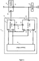
- FIG. 1 shows a block diagram of an exemplary embodiment of the device according to the invention for functional monitoring 1 in a simple design.
- FIG. 1 also shows a safety switching means 5 with an actuator 6 is switched.
- the safety switching means 5 an actuating input 10 and a switching output 11, which is in communication with the actuator 6, on.
- the function of the safety switching means 5 is to be monitored.
- the device for monitoring function 1 consists of an actuating means 2 and an evaluation means 3.
- the actuating means 2 is connected via an actuating output 9 to the actuating input 10 of the safety switching means 5.
- the actuating means 2 is used to deliver a signal via the actuating output 9 to the safety switching means 5. With the aid of this signal, the safety switching means 5 is switched when the safety switching means 5 is functioning properly. Therefore, this signal is also referred to as a switching signal.
- the actuating means 2 can deliver the switching signal, for example, in response to a signal at a control input 7 of the actuating means 2.
- the device for function monitoring 1 has a control means 4 which is connected to the actuating means 2 via the control input 7 of the actuating means 2.
- the control means 4 may for example deliver a signal to the control input 7, which causes the actuating means 2 to change the signal at the actuating output 9 such that the safety switching means 5 is switched, for example in response to a detected actuator error, such as welded relay contacts to open the safety switching means 5 and thus to disconnect the actuator 6 from the power supply.
- the actuating means 2 on a test input 8.
- the actuating means 2 the signal with the information received that a bump test is to be performed. In the embodiment shown, this is done by a signal at the test input and a simultaneous removal of the signal at the control input.
- the test input 8 of the actuating means 2 is connected to the control means 4. Via this connection, the control means 4 can control the execution of functional tests of the safety switching means 5. Function tests of the safety switching means 5 can be initiated cyclically or at irregular intervals via the test input 8. During a functional test, the actuating means 2, depending on the test signal obtained, the safety switching means 5 off and on again.
- the evaluation means 3 ensures that the functional test is terminated as quickly as possible and the operating mode is continued.
- the evaluation means 3 has a monitoring input 15, which is connected to the switching output 11 of the safety switching means 5.
- the evaluation means 3 With the help of this monitoring input 15 the evaluation means 3, the signal with the information about a change of a signal at the switching output 11 of the safety switching means 5 are provided.
- the evaluation means 3 changes the signals at the feedback output 14 and at the function reporting output 16.
- the signal with the information about the change of the signal at the switching output and thus on the respective switching state of the safety switching means 5 is provided by the evaluation 3 to the actuating means 2 via a feedback connection 12.
- the actuating means 2 can immediately reverse the signal change at the actuating output 9 and thus switch on the safety means 5 again, before the functional test is ended by the end of the test signal.
- the signal with the information about the switching state of the safety switching means 5 via aginasmeldausgang 16 of the evaluation means 3, the control means 4th made available.
- this signal is provided with this information regardless of whether the safety switching means 5 has been turned on again or not.
- the evaluation means 3 also has a control input 17 and a test input 18.
- the evaluation means 3 can distinguish between a shutdown of the safety switching means 5 due to a functional test or an intentional shutdown.
- the provision of the control input 17 and the test input 18 is only one possible implementation. There are also solutions where only one of the two inputs is necessary.
- this function can also be achieved, for example, in that the actuating means 2 is switched such that only when the functional test is displayed at the test input 8, the feedback signal can have an effect on the actuating output 9.
- the safety switching means 5 may be an electronic semiconductor switch. Alternatively, however, the safety switching means 5 can also be formed from a mechanical relay.
- the operating voltage of the actuator 6 and the operating voltage of the function monitoring device 1 is the same.
- the actuator 6 and the function monitoring device 1 could have different operating voltages.
- the switched operating voltage for the actuator 6 may be higher than the voltage of the device for functional monitoring 1.
- a means for reducing the voltage (not shown in the figures) may be arranged. This means could for example be formed by a voltage divider circuit or a transformer, each with or without voltage rectifier.
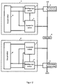
- FIG. 2 shows an embodiment of the inventive device for function monitoring 1 in redundant design.
- the security switching means 5, as well as the attached device for functional monitoring 1 executed twice.
- the control means 4 can also be implemented redundantly.
- the first safety switching means 5 switches the actuator 6 against the positive supply voltage, UB, the second safety switching means 5', the actuator 6 against the ground, GND, switches.
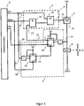
- FIG. 3 shows a realization of the in the FIGS. 1 and 2 shown actuating means 2 and evaluation means 3 by means of existing hardware components logic.
- the actuating means 2 is formed of an AND gate 21 and of an OR gate 22 with 2 inputs each.
- the control input 7 of the actuating means 2 is connected to the OR gate 22, so that a "1" signal at the control input 7, the safety switching means 5 is actuated.
- the output of the AND gate 21 is connected.
- the AND gate 21 combines the signal at the test input 8 and the feedback input 13 of the actuating means 2.
- this AND operation causes the safety switching means 5 to be switched on again immediately after a shutdown in connection with a functional test of the safety switching means 5. This happens here by the simultaneous application of a signal to the test input 8 and to the feedback input 13 of the actuating means 2.
- the signal at the feedback input 13 of the actuating means 2 is provided by the evaluation means 3.
- the function of the evaluation means 3 is to detect a shutdown during a functional test and this shutdown the control means 4 via a signal the function report output 16 and the actuating means 2 via a signal at the feedback input 13 display.
- the evaluation means 3 with 2 edge-triggered D flip-flops 19, 20 realized.
- the flip-flops 19, 20 are connected so that a signal change at the control input 7 and at the test input 8, the flip-flops 19, 20 initialized, ie the signals at the enable output 23 of the flip-flop 19 and the feedback output 14 of the flip-flop 20 are set to "0" so that they respond to "flanks" caused by the subsequent test procedure.
- a shutdown carried out by a functional test is thus registered as a signal change from "1" to "0", or from "0" to "1” by negating the flip-flop 19 connected to the monitoring input 15.
- the edge-triggered flip-flop 19 then changes the switching state at its outputs, so that the signal is set at the feedback output 14 of "0" to "1" to signal the actuator 2, the successful shutdown.
- the signal at the function reporting output 16 to which the control means 4 is connected which is shown here as a microcontroller, also changes.
- the signal at the functional signaling output 16 is stored in the memory of the microcontroller. This means that the signal is still displayed after switching on the safety switching means 5 and after the signal change to the control input 17. By the subsequent change of the signal at the test input 18, the flip-flops 19, 20 are brought back to the state before the functional test.
- FIG. 4a shows a state diagram for the control of the device according to the invention for functional monitoring in the embodiment, as shown in the FIG. 3 is shown in error-free operation.
- a signal at the control input 7 of the actuating means 2 the safety switching means 5 turns on and at the same time that the omission of this signal at the control input 7 of the actuating means 2, the safety switching means 5 turns off.
- FIG. 4b is a state diagram for the control of the device according to the invention for function monitoring, in the embodiment as shown in the FIG. 3 is shown when performing a functional test with reclosing and with a faultless safety switching means.
- test input 8 of the actuator 2 is set to "1" while the control input 7 is still at “1", thus turning on the safety switching means 5 in an on state to keep.
- this signal change at the test input 8 does not yet cause the safety switching means 5 to be switched off.
- the flip-flop 19 Due to the signal change at the monitoring input 15 of the evaluation means 3, caused by the switching off of the safety switching means 5, the flip-flop 19 is set, which in turn causes a signal change from "0" to "1" at the feedback input 13 of the actuating means 2. As shown in node 4, the "1" signal at the feedback input 13 of the actuating means 2, or the “1” signal at the feedback output 14 of the evaluation means 3 and the still pending test signal 8, the safety switching means 5 by a "1 "Signal at the operation input 10 is turned on again.
- Figure 4c is a state diagram for the control of the inventive device for monitoring function in the embodiment, as shown in the FIG. 3 is shown in the performance of a functional test in which the safety switching means 5 is not switched back on because of the presence of a fault.
- Fig. 5 shows a timing diagram for the control of the device according to the invention for functional monitoring 1 in the embodiments as shown in the FIGS. 1 to 3 shown in error-free operation.
- the test input 8 and the function message output 16 are in FIG. 5 for the sake of clarity, the operation input 10 and the switching output 11 of the safety switching means 5, the monitoring input 15 of the evaluation means 3 and the signal at the feedback input 13 of the actuating means 2 shown.
- FIG. 5 the implementation of a functional test is described.
- the input signal at the control input 7 is set to "1" and the input signal at the test input 8 is set to "0".
- the signal at the feedback input 13 is at "0".
- the function message signal at the function message output 16 is at "1" and the safety switching means 5 is closed.
- the state of the signals shown at time t 0 represents the normal operation.
- the connected actuator 6 is supplied with voltage.
- the software in the control means 4 permanently monitors the normal operation via the function reporting output 16, ie it checks the actual value at the safety switching means 5 with regard to deviations from the setpoint value at the control input 7.
- the functional test of the safety switching means 5 is prepared by the software in the control means 4. The preparation is done by setting test input 8 to "1". However, this does not start the actual function test.
- the safety switching means 5 is further controlled in accordance with the desired value at the actuating output 9 of the actuating means 2 and the connected actuator 6 is supplied with voltage.
- the preparation causes the actuating means 2 and the evaluation means 3 to be realized with flip-flops 19, 20, as shown in FIG. 3 is shown to respond to "flanks" caused by the test procedure described below.
- the actual functional test of the safety switching means 5 is started.
- the software in the control means 4 switches the setpoint at the control input 7 of the actuating means 2 from “1" to “0” and the actuating means 2 reacts by switching off the safety switching means 5 by setting the actuating input 10 of the safety switching means 5 to "0".
- the evaluation means 3 monitors the output level on the actuator 6, or on the safety switching means 5 through the monitoring input 15th
- the evaluation means 3 notes at this time that the safety switching means 5 has been switched off and reacts immediately with a "1" signal at the feedback input 13.
- the signal at the feedback input 13 is supplied to the actuating means 2, thereby initiating the reconnection of the safety switching means 5 by the actuating means 2 in that the signal at the operating input 10 of the safety switching means 5 is reset to 1.
- the control input 7 is still at "0".
- the actuator 6 By switching on again, the actuator 6 is supplied with voltage again. Since the evaluation means 3 automatically reacts to the successful functional test and the safety switching means 5 turns on again, the functional test for the connected actuator 6 is kept as short as possible.
- control means 4 has read in the signal at the function reporting output 16 of the evaluation means 3 and recognized the successfully performed function test and the signal at the control input 7 of the actuating means 2 is set by the control means 4 again from “0" to "1".
- the inputs and outputs again have the same states as before the execution of the function test.
- the control means 4 again controls the control input 7 of the actuating means 2.
- the signals in the in FIG. 5 shown and described above pulse diagram for driving the device according to the invention for functional monitoring 1 can also assume other states depending on the implementation with logical components at the various times shown. For example, all the signal states shown could be inverted.
Landscapes
- Physics & Mathematics (AREA)
- General Physics & Mathematics (AREA)
- Engineering & Computer Science (AREA)
- Automation & Control Theory (AREA)
- Safety Devices In Control Systems (AREA)
Claims (15)
- Un dispositif (1) de surveillance fonctionnelle d'un moyen de commutation de sécurité (5) qui peut être utilisé en particulier pour commuter un actionneur (6), le moyen de commutation de sécurité (5) comportant une entrée d'actionnement (10) et une sortie de commutation (11), le dispositif (1) comprenant :un moyen d'actionnement (2) avec une entrée de commande (7), une entrée de test (8), une entrée de retour (13) et une sortie d'actionnement (9) pour le relier à l'entrée d'actionnement (10) du moyen de commutation de sécurité (5), le moyen de commutation de sécurité (5) étant commuté dans un mode de fonctionnement à l'aide d'un signal à l'entrée de commande (7), et un test fonctionnel étant déclenché à l'aide d'un signal à l'entrée de test (8) ; etun moyen d'analyse (3) avec une entrée de surveillance (15) pour le relier à la sortie de commutation (11) du moyen de commutation de sécurité (5), une sortie de message fonctionnel (16) et une sortie de retour (14), le moyen d'actionnement (2) étant conçu, pour un test fonctionnel du moyen de commutation de-sécurité (5), pour modifier un signal à la sortie d'actionnement (9) en fonction d'un signal à l'entrée de test (8) et de l'entrée de commande (7), le moyen d'analyse (3) étant conçu pour détecter une modification du signal à la sortie de commutation (11) du moyen de commutation de sécurité (5) par l'intermédiaire de l'entrée de surveillance (11), pour transmettre à l'entrée de retour (13) du moyen d'actionnement (2) un signal avec une information sur la modification par l'intermédiaire de la sortie de retour (14) du moyen d'analyse (3) et pour fournir un signal avec une information sur la modification à la sortie de message fonctionnel (16) et, en outre, le moyen d'actionnement (2) étant conçu, lors d'un test fonctionnel en cas d'obtention d'un signal avec une information sur la modification du signal à la sortie de commutation (11) du moyen de commutation de sécurité (5), pour annuler aussitôt la modification de signal à la sortie d'actionnement (9).
- Le dispositif (1) de surveillance fonctionnelle selon la revendication 1, en cas d'obtention du signal avec l'information sur la modification du signal à la sortie de commutation (11) du moyen de commutation de sécurité (5), un signal se modifiant à l'entrée de retour (13) du moyen d'actionnement (2), et le moyen d'actionnement (2) étant conçu pour laisser le signal à la sortie d'actionnement (9) modifié tant que le signal à l'entrée de test (8) et le signal à l'entrée de retour (13) du moyen d'actionnement (2) ne se modifient pas.
- Le dispositif (1) de surveillance fonctionnelle selon une des revendications 1 ou 2, le signal à la sortie de commutation (11) du moyen de commutation de sécurité (5) se modifiant du fait de la modification du signal à la sortie d'actionnement (9).
- Le dispositif (1) de surveillance fonctionnelle selon une des revendications 1 à 3, le moyen d'analyse (3) comportant une entrée de test (18).
- Le dispositif (1) de surveillance fonctionnelle selon la revendication 4, le signal avec l'information sur la modification du signal à la sortie de commutation (11) étant fourni à la sortie de message fonctionnel (16) au moins tant qu'un signal est fourni à l'entrée de test (18) du moyen d'analyse (3).
- Le dispositif (1) de surveillance fonctionnelle selon une des revendications 1 à 5, le moyen d'actionnement (2) étant conçu pour modifier le signal à la sortie de commutation (11) du moyen de commutation de sécurité (5) en réaction à un signal à l'entrée de commande (7).
- Le dispositif (1) de surveillance fonctionnelle selon une des revendications 1 à 6, le moyen d'analyse (3) comportant une entrée de commande (17), et le moyen d'analyse (3) étant conçu, après l'obtention d'un signal avec une information sur la modification du signal à la sortie de commutation (11) du moyen de commutation de sécurité (5), pour remettre à l'état initial les signaux à la sortie de retour (14) et à la sortie de message fonctionnel (16) en réaction à une modification du signal à l'entrée de commande (17) .
- Le dispositif (1) de surveillance fonctionnelle selon une des revendications 1 à 7, le moyen d'actionnement (2) et le moyen d'analyse (3) réalisant le fonctionnement défini dans les revendications respectives avec une logique câblée.
- Le dispositif (1) de surveillance fonctionnelle selon une des revendications 1 à 8, le moyen d'actionnement (2) étant réalisé avec des portes logiques et le moyen d'analyse (3) étant réalisé avec des bascules bistables (19, 20).
- Le dispositif (1) de surveillance fonctionnelle selon une des revendications 1 à 9, comprenant en outre :un moyen de commande (4) qui est relié à l'entrée de test (8) du moyen d'actionnement (2) et à la sortie de message fonctionnel (16) du moyen d'analyse (3).
- Le dispositif (1) de surveillance fonctionnelle selon une des revendications 9 ou 10, le moyen de commande (4) étant conçu pour déclencher un test fonctionnel à intervalles périodiques.
- Le dispositif (1) de surveillance fonctionnelle selon la revendication 11, le moyen de commande (4) déclenchant le test fonctionnel en modifiant le signal à l'entrée de test (8) et à l'entrée de commande (7) du moyen d'actionnement (2).
- Le dispositif (1) de surveillance fonctionnelle selon une des revendications 11 ou 12, l'intervalle périodique étant compris entre 5 millisecondes et 15 minutes.
- Le dispositif (1) de surveillance fonctionnelle selon une des revendications 9 à 13, le moyen de commande (4) contenant une logique programmable.
- Un procédé de surveillance fonctionnelle d'un moyen de commutation de sécurité (5) qui peut être utilisé en particulier pour commuter un actionneur (6), le procédé consistant à :modifier un signal à une sortie d'actionnement (9) d'un moyen d'actionnement (2), laquelle est reliée à une entrée d'actionnement (10) du moyen de commutation de sécurité (5), en fonction d'un signal à une entrée de test (8) et à une entrée de commande (7) du moyen d'actionnement (2), le moyen de commutation de sécurité (5) étant commuté dans un mode de fonctionnement à l'aide d'un signal à l'entrée de commande (7), et un test fonctionnel étant déclenché à l'aide d'un signal à l'entrée de test (8) ;détecter sur un moyen d'analyse (3) une modification d'un signal à une sortie de commutation (11) du moyen de commutation de sécurité (5) ;fournir à une sortie de message fonctionnel (16) du moyen d'analyse (3) un signal avec une information sur la modification du signal à la sortie de commutation (11) du moyen de commutation de sécurité (5) et transmettre le signal avec l'information, sur la modification du signal à une entrée de retour (13) du moyen d'actionnement (2) ; etannuler la -modification de signal à la sortie d'actionnement (9) du moyen d'actionnement (2) en cas de test fonctionnel en fonction de l'obtention du signal avec l'information sur la modification.
Applications Claiming Priority (1)
| Application Number | Priority Date | Filing Date | Title |
|---|---|---|---|
| DE102015200057.5A DE102015200057A1 (de) | 2015-01-07 | 2015-01-07 | Vorrichtung und Verfahren zur Funktionsüberwachung eines Sicherheitsschaltmittels |
Publications (2)
| Publication Number | Publication Date |
|---|---|
| EP3043220A1 EP3043220A1 (fr) | 2016-07-13 |
| EP3043220B1 true EP3043220B1 (fr) | 2017-10-11 |
Family
ID=55023912
Family Applications (1)
| Application Number | Title | Priority Date | Filing Date |
|---|---|---|---|
| EP15200414.9A Active EP3043220B1 (fr) | 2015-01-07 | 2015-12-16 | Dispositif et procede de surveillance fonctionnelle d'un moyen de commutation de securite |
Country Status (3)
| Country | Link |
|---|---|
| US (1) | US9778320B2 (fr) |
| EP (1) | EP3043220B1 (fr) |
| DE (1) | DE102015200057A1 (fr) |
Families Citing this family (6)
| Publication number | Priority date | Publication date | Assignee | Title |
|---|---|---|---|---|
| EP3244221B1 (fr) * | 2016-05-11 | 2021-08-04 | TRUMPF Schweiz AG | Systeme de surveillance d'un capteur de securite et procede de surveillance d'un capteur de securite |
| CN107732875A (zh) * | 2016-08-12 | 2018-02-23 | 通用电气公司 | 固态断路器及电机驱动系统 |
| EP3534226B1 (fr) * | 2018-03-02 | 2022-02-09 | Emm! solutions GmbH | Système de contrôle modulaire |
| DE102018114425A1 (de) * | 2018-06-15 | 2019-12-19 | Phoenix Contact Gmbh & Co. Kg | Schaltüberwachungsvorrichtung |
| CN111446118B (zh) * | 2020-04-29 | 2024-05-28 | 上海乐研电气有限公司 | 具有仿真校验功能的气体密度继电器及其仿真校验方法 |
| DE102021122078A1 (de) | 2021-08-26 | 2023-03-02 | WAGO Verwaltungsgesellschaft mit beschränkter Haftung | Schaltung zum steuern einer last |
Citations (1)
| Publication number | Priority date | Publication date | Assignee | Title |
|---|---|---|---|---|
| US20080007879A1 (en) * | 2006-06-01 | 2008-01-10 | Albert Zaretsky | Gfci with self-test and remote annunciation capabilities |
Family Cites Families (8)
| Publication number | Priority date | Publication date | Assignee | Title |
|---|---|---|---|---|
| DE19508841C2 (de) | 1994-11-18 | 2002-03-28 | Leuze Electronic Gmbh & Co | Sicherheitsschalteranordnung |
| DE10109864A1 (de) * | 2001-03-01 | 2002-09-19 | Siemens Ag | Sicherheitsschaltvorrichtung |
| US7973533B2 (en) * | 2008-02-27 | 2011-07-05 | Vertical Power, Inc. | In-circuit testing for integrity of solid-state switches |
| EP2149826B1 (fr) | 2008-08-01 | 2011-11-30 | Siemens Aktiengesellschaft | Circuit de sécurité avec contacteurs pour générer un signal de commutation |
| US7675308B1 (en) * | 2008-08-20 | 2010-03-09 | Faraday Technology Corp. | Test circuit and test method for power switch |
| US9673611B2 (en) * | 2012-02-21 | 2017-06-06 | Hamilton Sundstrand Corporation | Self-test of over-current fault detection |
| CN103458579B (zh) * | 2013-08-29 | 2015-06-10 | 矽力杰半导体技术(杭州)有限公司 | 负载驱动电路以及方法 |
| US9329237B2 (en) * | 2014-01-10 | 2016-05-03 | Freescale Semiconductor, Inc. | Switch detection device and method of use |
-
2015
- 2015-01-07 DE DE102015200057.5A patent/DE102015200057A1/de active Pending
- 2015-12-16 EP EP15200414.9A patent/EP3043220B1/fr active Active
-
2016
- 2016-01-06 US US14/988,984 patent/US9778320B2/en active Active
Patent Citations (1)
| Publication number | Priority date | Publication date | Assignee | Title |
|---|---|---|---|---|
| US20080007879A1 (en) * | 2006-06-01 | 2008-01-10 | Albert Zaretsky | Gfci with self-test and remote annunciation capabilities |
Also Published As
| Publication number | Publication date |
|---|---|
| DE102015200057A1 (de) | 2016-07-07 |
| US9778320B2 (en) | 2017-10-03 |
| EP3043220A1 (fr) | 2016-07-13 |
| US20160195582A1 (en) | 2016-07-07 |
Similar Documents
| Publication | Publication Date | Title |
|---|---|---|
| EP3043220B1 (fr) | Dispositif et procede de surveillance fonctionnelle d'un moyen de commutation de securite | |
| EP1738382B1 (fr) | Dispositif de commutation de securite pour circuit de securite | |
| EP2208215B1 (fr) | Dispositif de commutation et procédé de contrôle d'un relais électromagnétique | |
| DE2923511C3 (de) | Elektronische Einrichtung zur Überwachung einer Mehrzahl laufender Fäden an einer Textilmaschine | |
| WO2001075532A1 (fr) | Interrupteur de securite et procede pour ajuster un mode de fonctionnement pour interrupteur de securite | |
| DE102010007784A1 (de) | Vorrichtung zur elektrischen Stromkreisüberwachung | |
| EP2656365B1 (fr) | Circuit de commande d'un relais électromagnétique | |
| AT507540B1 (de) | Verfahren zur ansteuerung einer gleichstrommaschine | |
| WO2006099935A1 (fr) | Dispositif de coupure de securite servant a deconnecter un recepteur electrique de maniere sure | |
| EP2546852B1 (fr) | Relais de sécurité bistable | |
| DE102011010512A1 (de) | Passive Sicherheitsschaltung | |
| EP1594021B1 (fr) | Dispositif de circuit et procédé de test de contacts de commutation d'un circuit numérique de sortie | |
| EP0505774B1 (fr) | Dispositif de commutation de sécurité | |
| DE102006027135B3 (de) | Verfahren zum Betrieb einer Vorrichtung, insbesondere eines Sicherheitsschalters, und die Vorrichtung | |
| EP2215533B1 (fr) | Dispositif de commande pour un système de commutation de sécurité à surveillance intégrée de la tension d'alimentation | |
| EP2461341A1 (fr) | Module de commutation protégé contre les erreurs et procédé de fonctionnement | |
| WO2015180806A1 (fr) | Relais électronique | |
| EP1652203B1 (fr) | Installation de protection adaptee a des circuits en cascade et procede correspondant permettant la realisation de connexions securisees | |
| DE102009050071B3 (de) | Steuereinrichtung und Verfahren zur spannungspotentialgetriebenen Ansteuerung von Feldgeräten | |
| BE1031305B1 (de) | Schaltgerät zum elektrischen Ein- und Ausschalten einer mit einer Gleichspannungs-Versorgungseinrichtung verbindbaren elektrischen Last sowie Verfahren zum Betreiben eines solchen Schaltgeräts | |
| EP2899872A1 (fr) | Système d'alimentation pour un entraînement à courant continu et procédé de désactivation de sécurité d'un entraînement à courant continu | |
| EP3404431B1 (fr) | Procédé de surveillance du fonctionnement d'une interface binaire et interface binaire correspondante | |
| DE10220349B4 (de) | Verfahren und Vorrichtung zum Verbinden einer Versorgungsgleichspannung mit einer Last und zum Trennen der Versorgungsgleichspannung von der Last | |
| EP4336537A1 (fr) | Dispositif relais et appareil de commutation de sécurité doté d'au moins un dispositif relais | |
| DE102007038889A1 (de) | Elektronisches Steuergerät mit Notabschaltung und Verfahren zur Prüfung eines Steuergeräts und zur Prüfung eines Systems von Steuergeräten |
Legal Events
| Date | Code | Title | Description |
|---|---|---|---|
| PUAI | Public reference made under article 153(3) epc to a published international application that has entered the european phase |
Free format text: ORIGINAL CODE: 0009012 |
|
| AK | Designated contracting states |
Kind code of ref document: A1 Designated state(s): AL AT BE BG CH CY CZ DE DK EE ES FI FR GB GR HR HU IE IS IT LI LT LU LV MC MK MT NL NO PL PT RO RS SE SI SK SM TR |
|
| AX | Request for extension of the european patent |
Extension state: BA ME |
|
| 17P | Request for examination filed |
Effective date: 20161114 |
|
| RBV | Designated contracting states (corrected) |
Designated state(s): AL AT BE BG CH CY CZ DE DK EE ES FI FR GB GR HR HU IE IS IT LI LT LU LV MC MK MT NL NO PL PT RO RS SE SI SK SM TR |
|
| 17Q | First examination report despatched |
Effective date: 20170105 |
|
| GRAP | Despatch of communication of intention to grant a patent |
Free format text: ORIGINAL CODE: EPIDOSNIGR1 |
|
| INTG | Intention to grant announced |
Effective date: 20170802 |
|
| GRAS | Grant fee paid |
Free format text: ORIGINAL CODE: EPIDOSNIGR3 |
|
| GRAA | (expected) grant |
Free format text: ORIGINAL CODE: 0009210 |
|
| AK | Designated contracting states |
Kind code of ref document: B1 Designated state(s): AL AT BE BG CH CY CZ DE DK EE ES FI FR GB GR HR HU IE IS IT LI LT LU LV MC MK MT NL NO PL PT RO RS SE SI SK SM TR |
|
| REG | Reference to a national code |
Ref country code: GB Ref legal event code: FG4D Free format text: NOT ENGLISH |
|
| REG | Reference to a national code |
Ref country code: CH Ref legal event code: EP |
|
| REG | Reference to a national code |
Ref country code: IE Ref legal event code: FG4D Free format text: LANGUAGE OF EP DOCUMENT: GERMAN |
|
| REG | Reference to a national code |
Ref country code: AT Ref legal event code: REF Ref document number: 936584 Country of ref document: AT Kind code of ref document: T Effective date: 20171115 |
|
| REG | Reference to a national code |
Ref country code: DE Ref legal event code: R096 Ref document number: 502015002083 Country of ref document: DE |
|
| REG | Reference to a national code |
Ref country code: NL Ref legal event code: MP Effective date: 20171011 |
|
| REG | Reference to a national code |
Ref country code: LT Ref legal event code: MG4D |
|
| PG25 | Lapsed in a contracting state [announced via postgrant information from national office to epo] |
Ref country code: NL Free format text: LAPSE BECAUSE OF FAILURE TO SUBMIT A TRANSLATION OF THE DESCRIPTION OR TO PAY THE FEE WITHIN THE PRESCRIBED TIME-LIMIT Effective date: 20171011 |
|
| PG25 | Lapsed in a contracting state [announced via postgrant information from national office to epo] |
Ref country code: SE Free format text: LAPSE BECAUSE OF FAILURE TO SUBMIT A TRANSLATION OF THE DESCRIPTION OR TO PAY THE FEE WITHIN THE PRESCRIBED TIME-LIMIT Effective date: 20171011 Ref country code: ES Free format text: LAPSE BECAUSE OF FAILURE TO SUBMIT A TRANSLATION OF THE DESCRIPTION OR TO PAY THE FEE WITHIN THE PRESCRIBED TIME-LIMIT Effective date: 20171011 Ref country code: FI Free format text: LAPSE BECAUSE OF FAILURE TO SUBMIT A TRANSLATION OF THE DESCRIPTION OR TO PAY THE FEE WITHIN THE PRESCRIBED TIME-LIMIT Effective date: 20171011 Ref country code: NO Free format text: LAPSE BECAUSE OF FAILURE TO SUBMIT A TRANSLATION OF THE DESCRIPTION OR TO PAY THE FEE WITHIN THE PRESCRIBED TIME-LIMIT Effective date: 20180111 Ref country code: LT Free format text: LAPSE BECAUSE OF FAILURE TO SUBMIT A TRANSLATION OF THE DESCRIPTION OR TO PAY THE FEE WITHIN THE PRESCRIBED TIME-LIMIT Effective date: 20171011 |
|
| PG25 | Lapsed in a contracting state [announced via postgrant information from national office to epo] |
Ref country code: GR Free format text: LAPSE BECAUSE OF FAILURE TO SUBMIT A TRANSLATION OF THE DESCRIPTION OR TO PAY THE FEE WITHIN THE PRESCRIBED TIME-LIMIT Effective date: 20180112 Ref country code: RS Free format text: LAPSE BECAUSE OF FAILURE TO SUBMIT A TRANSLATION OF THE DESCRIPTION OR TO PAY THE FEE WITHIN THE PRESCRIBED TIME-LIMIT Effective date: 20171011 Ref country code: LV Free format text: LAPSE BECAUSE OF FAILURE TO SUBMIT A TRANSLATION OF THE DESCRIPTION OR TO PAY THE FEE WITHIN THE PRESCRIBED TIME-LIMIT Effective date: 20171011 Ref country code: IS Free format text: LAPSE BECAUSE OF FAILURE TO SUBMIT A TRANSLATION OF THE DESCRIPTION OR TO PAY THE FEE WITHIN THE PRESCRIBED TIME-LIMIT Effective date: 20180211 Ref country code: BG Free format text: LAPSE BECAUSE OF FAILURE TO SUBMIT A TRANSLATION OF THE DESCRIPTION OR TO PAY THE FEE WITHIN THE PRESCRIBED TIME-LIMIT Effective date: 20180111 Ref country code: HR Free format text: LAPSE BECAUSE OF FAILURE TO SUBMIT A TRANSLATION OF THE DESCRIPTION OR TO PAY THE FEE WITHIN THE PRESCRIBED TIME-LIMIT Effective date: 20171011 |
|
| REG | Reference to a national code |
Ref country code: DE Ref legal event code: R097 Ref document number: 502015002083 Country of ref document: DE |
|
| PG25 | Lapsed in a contracting state [announced via postgrant information from national office to epo] |
Ref country code: DK Free format text: LAPSE BECAUSE OF FAILURE TO SUBMIT A TRANSLATION OF THE DESCRIPTION OR TO PAY THE FEE WITHIN THE PRESCRIBED TIME-LIMIT Effective date: 20171011 Ref country code: EE Free format text: LAPSE BECAUSE OF FAILURE TO SUBMIT A TRANSLATION OF THE DESCRIPTION OR TO PAY THE FEE WITHIN THE PRESCRIBED TIME-LIMIT Effective date: 20171011 Ref country code: CZ Free format text: LAPSE BECAUSE OF FAILURE TO SUBMIT A TRANSLATION OF THE DESCRIPTION OR TO PAY THE FEE WITHIN THE PRESCRIBED TIME-LIMIT Effective date: 20171011 Ref country code: SK Free format text: LAPSE BECAUSE OF FAILURE TO SUBMIT A TRANSLATION OF THE DESCRIPTION OR TO PAY THE FEE WITHIN THE PRESCRIBED TIME-LIMIT Effective date: 20171011 |
|
| PLBE | No opposition filed within time limit |
Free format text: ORIGINAL CODE: 0009261 |
|
| STAA | Information on the status of an ep patent application or granted ep patent |
Free format text: STATUS: NO OPPOSITION FILED WITHIN TIME LIMIT |
|
| PG25 | Lapsed in a contracting state [announced via postgrant information from national office to epo] |
Ref country code: PL Free format text: LAPSE BECAUSE OF FAILURE TO SUBMIT A TRANSLATION OF THE DESCRIPTION OR TO PAY THE FEE WITHIN THE PRESCRIBED TIME-LIMIT Effective date: 20171011 Ref country code: IT Free format text: LAPSE BECAUSE OF FAILURE TO SUBMIT A TRANSLATION OF THE DESCRIPTION OR TO PAY THE FEE WITHIN THE PRESCRIBED TIME-LIMIT Effective date: 20171011 Ref country code: RO Free format text: LAPSE BECAUSE OF FAILURE TO SUBMIT A TRANSLATION OF THE DESCRIPTION OR TO PAY THE FEE WITHIN THE PRESCRIBED TIME-LIMIT Effective date: 20171011 Ref country code: SM Free format text: LAPSE BECAUSE OF FAILURE TO SUBMIT A TRANSLATION OF THE DESCRIPTION OR TO PAY THE FEE WITHIN THE PRESCRIBED TIME-LIMIT Effective date: 20171011 |
|
| 26N | No opposition filed |
Effective date: 20180712 |
|
| REG | Reference to a national code |
Ref country code: IE Ref legal event code: MM4A |
|
| PG25 | Lapsed in a contracting state [announced via postgrant information from national office to epo] |
Ref country code: LU Free format text: LAPSE BECAUSE OF NON-PAYMENT OF DUE FEES Effective date: 20171216 Ref country code: MT Free format text: LAPSE BECAUSE OF FAILURE TO SUBMIT A TRANSLATION OF THE DESCRIPTION OR TO PAY THE FEE WITHIN THE PRESCRIBED TIME-LIMIT Effective date: 20171011 |
|
| REG | Reference to a national code |
Ref country code: FR Ref legal event code: ST Effective date: 20180831 |
|
| REG | Reference to a national code |
Ref country code: BE Ref legal event code: MM Effective date: 20171231 |
|
| PG25 | Lapsed in a contracting state [announced via postgrant information from national office to epo] |
Ref country code: FR Free format text: LAPSE BECAUSE OF NON-PAYMENT OF DUE FEES Effective date: 20180102 Ref country code: IE Free format text: LAPSE BECAUSE OF NON-PAYMENT OF DUE FEES Effective date: 20171216 |
|
| PG25 | Lapsed in a contracting state [announced via postgrant information from national office to epo] |
Ref country code: BE Free format text: LAPSE BECAUSE OF NON-PAYMENT OF DUE FEES Effective date: 20171231 Ref country code: SI Free format text: LAPSE BECAUSE OF FAILURE TO SUBMIT A TRANSLATION OF THE DESCRIPTION OR TO PAY THE FEE WITHIN THE PRESCRIBED TIME-LIMIT Effective date: 20171011 |
|
| PG25 | Lapsed in a contracting state [announced via postgrant information from national office to epo] |
Ref country code: MC Free format text: LAPSE BECAUSE OF FAILURE TO SUBMIT A TRANSLATION OF THE DESCRIPTION OR TO PAY THE FEE WITHIN THE PRESCRIBED TIME-LIMIT Effective date: 20171011 Ref country code: HU Free format text: LAPSE BECAUSE OF FAILURE TO SUBMIT A TRANSLATION OF THE DESCRIPTION OR TO PAY THE FEE WITHIN THE PRESCRIBED TIME-LIMIT; INVALID AB INITIO Effective date: 20151216 |
|
| REG | Reference to a national code |
Ref country code: CH Ref legal event code: PL |
|
| PG25 | Lapsed in a contracting state [announced via postgrant information from national office to epo] |
Ref country code: CY Free format text: LAPSE BECAUSE OF FAILURE TO SUBMIT A TRANSLATION OF THE DESCRIPTION OR TO PAY THE FEE WITHIN THE PRESCRIBED TIME-LIMIT Effective date: 20171011 |
|
| PG25 | Lapsed in a contracting state [announced via postgrant information from national office to epo] |
Ref country code: MK Free format text: LAPSE BECAUSE OF FAILURE TO SUBMIT A TRANSLATION OF THE DESCRIPTION OR TO PAY THE FEE WITHIN THE PRESCRIBED TIME-LIMIT Effective date: 20171011 |
|
| PG25 | Lapsed in a contracting state [announced via postgrant information from national office to epo] |
Ref country code: CH Free format text: LAPSE BECAUSE OF NON-PAYMENT OF DUE FEES Effective date: 20181231 Ref country code: LI Free format text: LAPSE BECAUSE OF NON-PAYMENT OF DUE FEES Effective date: 20181231 |
|
| PG25 | Lapsed in a contracting state [announced via postgrant information from national office to epo] |
Ref country code: TR Free format text: LAPSE BECAUSE OF FAILURE TO SUBMIT A TRANSLATION OF THE DESCRIPTION OR TO PAY THE FEE WITHIN THE PRESCRIBED TIME-LIMIT Effective date: 20171011 |
|
| PG25 | Lapsed in a contracting state [announced via postgrant information from national office to epo] |
Ref country code: PT Free format text: LAPSE BECAUSE OF FAILURE TO SUBMIT A TRANSLATION OF THE DESCRIPTION OR TO PAY THE FEE WITHIN THE PRESCRIBED TIME-LIMIT Effective date: 20171011 |
|
| PG25 | Lapsed in a contracting state [announced via postgrant information from national office to epo] |
Ref country code: AL Free format text: LAPSE BECAUSE OF FAILURE TO SUBMIT A TRANSLATION OF THE DESCRIPTION OR TO PAY THE FEE WITHIN THE PRESCRIBED TIME-LIMIT Effective date: 20171011 |
|
| GBPC | Gb: european patent ceased through non-payment of renewal fee |
Effective date: 20191216 |
|
| PG25 | Lapsed in a contracting state [announced via postgrant information from national office to epo] |
Ref country code: GB Free format text: LAPSE BECAUSE OF NON-PAYMENT OF DUE FEES Effective date: 20191216 |
|
| REG | Reference to a national code |
Ref country code: AT Ref legal event code: MM01 Ref document number: 936584 Country of ref document: AT Kind code of ref document: T Effective date: 20201216 |
|
| PG25 | Lapsed in a contracting state [announced via postgrant information from national office to epo] |
Ref country code: AT Free format text: LAPSE BECAUSE OF NON-PAYMENT OF DUE FEES Effective date: 20201216 |
|
| P01 | Opt-out of the competence of the unified patent court (upc) registered |
Effective date: 20230522 |
|
| PGFP | Annual fee paid to national office [announced via postgrant information from national office to epo] |
Ref country code: DE Payment date: 20251229 Year of fee payment: 11 |