EP3043538A1 - Ensemble de positionnement pour appareil électronique - Google Patents
Ensemble de positionnement pour appareil électronique Download PDFInfo
- Publication number
- EP3043538A1 EP3043538A1 EP13884968.2A EP13884968A EP3043538A1 EP 3043538 A1 EP3043538 A1 EP 3043538A1 EP 13884968 A EP13884968 A EP 13884968A EP 3043538 A1 EP3043538 A1 EP 3043538A1
- Authority
- EP
- European Patent Office
- Prior art keywords
- poles
- magnetic unit
- housing
- electronic device
- magnetic
- Prior art date
- Legal status (The legal status is an assumption and is not a legal conclusion. Google has not performed a legal analysis and makes no representation as to the accuracy of the status listed.)
- Withdrawn
Links
Images


Classifications
-
- H—ELECTRICITY
- H04—ELECTRIC COMMUNICATION TECHNIQUE
- H04M—TELEPHONIC COMMUNICATION
- H04M1/00—Substation equipment, e.g. for use by subscribers
- H04M1/02—Constructional features of telephone sets
- H04M1/04—Supports for telephone transmitters or receivers
-
- H—ELECTRICITY
- H01—ELECTRIC ELEMENTS
- H01F—MAGNETS; INDUCTANCES; TRANSFORMERS; SELECTION OF MATERIALS FOR THEIR MAGNETIC PROPERTIES
- H01F7/00—Magnets
- H01F7/02—Permanent magnets [PM]
- H01F7/0231—Magnetic circuits with PM for power or force generation
- H01F7/0252—PM holding devices
-
- G—PHYSICS
- G06—COMPUTING OR CALCULATING; COUNTING
- G06F—ELECTRIC DIGITAL DATA PROCESSING
- G06F1/00—Details not covered by groups G06F3/00 - G06F13/00 and G06F21/00
- G06F1/16—Constructional details or arrangements
- G06F1/1613—Constructional details or arrangements for portable computers
- G06F1/1628—Enclosures for carrying portable computers with peripheral devices, e.g. cases for a laptop and a printer
Definitions
- the present invention relates to a set of positioning component which includes a back side for fixing on the back of an electronic device, and includes a housing with a first magnetic unit and with multi-poles, the electronic device has therein a supporting piece having a second magnetic unit with multi-poles, by having the characteristic of magnetic adsorption as well as mutual rejection, the housing and the supporting piece can mutually fast positioning and detaching against each other, in order to increase their convenience of use.
- the present invention provides a set of positioning component for a mobile phone, a tablet computer, a digital picture frame, a driving recorder, a monitor, and a displayer etc. for an electronic device, and especially to a set of positioning component for an electronic device which can make positioning of the electronic device by magnetic adsorption from a special angular direction, or otherwise can make separation as well as detaching of the electronic device by a biased rotating mode.
- a clamping arm between the electronic device and the supporting rack can be provided for locking tight, by this way, when the user moves the electronic device for carrying, he must detach the electronic device down from the supporting rack for carrying it, this is quite inconvenient in use.
- a tablet computer or a mobile phone used in a household or an office for document treatment or reading normally is put to form an upright position, whereas when it is carried into a car for viewing a cinematograph or multimedia, it is put at a horizontal position.
- a tablet computer or a mobile phone we frequently need an operation of positioning and detachment, and need a random swiveling adjustment between the two positions.
- the products in the market evidently are lackof satisfaction tomeet such necessity.
- the inventor of the present application provides after studying and based on his professional experience of years in the field of production, manufacturing and designing to overcome the defects of the conventional technique.
- the main object of the present invention is resided in providing a set of positioning component that can make fast positioning of the electronic device by magnetic adsorption from a special angular direction, or otherwise can make fast separation as well as detaching of the electronic device by a biased rotation.
- the electronic device of the set of positioning component includes:
- a supporting piece is provided in the second magnetic unit with multi-poles (including multiple S and N), each magnetic polarity (S or N) of the second magnetic unit is contrarily provided relatively to the first multi-poles (including multiple S and N), in order to render the first magnetic unit in the housing to do magnetic adsorption on the second magnetic unit withmulti-poles (including multiples and N) from a special angular direction, or otherwise make separation as well as detaching of the first magnetic unit withmulti-poles (including multiple S and N)do its biased rotating against the second magnetic unit with multi-poles (including multiple S and N).
- the housing can be fixed on a back side of an electronic device in advance, and the electronic device is connected with the housing to form one body, and makes the supporting piece be provided on a chair, a desk, a wall or on an inner side of a windshield window of a car or on a suitable electronic device in advance, in this way, the housing on the back of the electronic device can be stuck to the supporting piece along a special angular direction, so that each polarity (S or N) of the first magnetic unit with multi-poles (including multiple S and N) is provided with contrary magnetic polarity relative to that of the second magnetic unit with multi-poles, so that the multi- poles of the first magnetic unit can strongly adsorbed on the second magnetic unit with multi-poles (including multiple S and N) through the above said housing and the above said supporting piece, and makes fast positioning of the electronic device on the supporting piece.
- S or N polarity of the first magnetic unit with multi-poles
- the multi-poles of the first magnetic unit can strongly adsorbed on the second magnetic unit with multi
- the electronic device When it is desired to detach the electronic device, it needs only to make biased rotation of the electronic device along the mutually contact surfaces of the housing with the supporting piece, and this renders the poles (including multiple S and N) of the first magnetic unit in the housing do biased rotation along with the electronic device. So that the first magnetic unit in the housing does biased rotation along with the electronic device to fast reject and separate mutually with the second magnetic unit with multi-poles (including multiple S and N), thereby the electronic device can be easily taken off from the supporting piece along with the housing.
- the electronic device of the present invention can do fast positioning and detachment for the electronic device, the electronic device can be moved for use or positioned at any time, for conveniently viewing the multi-media and vision messages at any time.
- the multi-poles (including multiple S and N) can be divided into 8 or its double by numeral and are arranged to equally occupying 360 degrees, this can make the relative angles between the housing and the supporting piece be at the magnetic adsorption states at least at the degree numbers 0, 90, 180 and 270. These especially suit the portable electronic devices with mobile phones, tablet computer, digital picture frame etc.
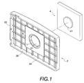
- FIG. 1 is a perspective view in practice of a preferred embodiment of the present invention
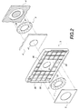
- Fig. 2 is an anatomic perspective view of Fig. 1
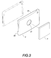
- Fig. 3 is a perspective view showing another view point of Fig. 1
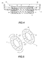
- Fig. 4 is a sectional view of the embodiment of Fig. 1
- Fig. 5 is a schematic perspective view showing the embodiment of the first magnetic unit and the second magnetic unit with multi-poles (including multiple S and N) of Fig. 4
- Fig. 6 is a sectional view showing the embodiment of Fig. 4 in use
- Fig. 7 is a schematic perspective view showing the embodiment of the first magnetic unit and the second magnetic unit of Fig. 6 with multi- poles (including multiple S and N).
- a set of component for an electronic device which includes a housing 3 which is fixed on a back side of an electronic device and is provided with a first magnetic unit 1 with multi-poles (including multiple S and N), and includes a supporting piece 4 which is provided therein with a second magnetic unit 2 with multi-poles (including multiple S andN).
- the housing 3 is provided with an engaging cover 30 that can cover the back of the electronic device, the housing 3 can take plastic or rubber as its forming material, the engaging cover 30 and the back of the electronic device can mutually tightly match with each other in order to fix the electronic device.
- the housing 3 is provided therein with a first magnetic unit 1 with multi-poles (including multiple S and N) at the central bottom of the engaging cover 30; the multi-poles (including multiple S and N) 11, 12 of the first magnetic unit 1 are arranged in a circular ring, the magnetic polarity (S or N) of every two neighboring magnetic poles (including multiple S and N) 11, 12 of the first magnetic unit 1 are mutually contrarily provided, for instance, the poles 11 are all of N poles, while their neighboring magnetic-poles 12 are all of S poles.
- the magnetic-poles 21, 22 of the second magnetic unit 2 are arranged and contrarily provided relatively to the multi-poles 12, 11 relatively of the first magnetic unit 1; the magnetic-poles 21, 22 of the second magnetic unit 2 are also mutually arranged and contrarily provided, for instance, the poles 21 are all of N poles, while their neighboring magnetic-poles 22 are all of S poles.
- the first magnetic unit 1 with multi-poles 12, 11 in the housing 3 does magnetic adsorption on the second magnetic unit 2 with multi-poles 21, 22 from a special angular direction, or otherwise the first magnetic unit 1 with multi- poles 12, 11 does its biased rotating to make separation as well as detaching from the second magnetic unit 2 with multi-poles 21, 22.
- the engaging cover 30 of the housing 3 can be fixed on a back side of the electronic device in advance, and the electronic device is connected with the housing 3 to form one body, while the supporting piece 4 can be provided on a chair, a desk, a wall or on an inner side of a windshield window of a car or on a suitable electronic device in advance,
- the housing 3 on the back side of the electronic device can be stuck to the supporting piece 4 along a special angular direction, and make the multi-poles 12, 11 of the first magnetic unit confront the multi-poles 21, 22 of the second magnetic unit 2, so that poles N of the first magnetic unit 1 confront the poles S of the second magnetic unit 2, and poles S of the first magnetic unit 1 confront the poles N of the second magnetic unit 2, so that the multi-poles 12, 11 of the first magnetic unit 1 can strongly adsorbed on the multi-poles 21 , 22 of the second magnetic unit 2 through the above said housing 3 and the above said supporting piece 4, and makes fast positioning the back of the electronic device on the supporting piece 4.
- the electronic device When it is desired to detach the electronic device, it needs only to make biased rotation of the electronic device along the mutually contact surfaces of the housing 3 with the supporting piece 4 to render the poles 11, 12 of the first magnetic unit 1 in the housing 3 to do biased rotation along with the electronic device, to have the poles 11, 12 of the first magnetic unit 1 to meet the multi-poles 21, 22 of the second magnetic unit 2 of the same magnetic polarities (S or N), i.e., the S polarities of the first magnetic unit 1 meet the S polarities of the second magnetic unit 2, the N polarities of the first magnetic unit 1 meet the N polarities of the second magnetic unit 2.
- S or N magnetic polarities
- the first magnetic unit 1 with multi-poles 11, 12 in the housing 3 does biased rotation along with the electronic device to reject and separate from the second magnetic unit 2 with multi-poles 21, 22 in the supporting piece 4, thereby the electronic device can be easily taken off from the supporting piece 4 along with housing 3.
- the electronic device can be fast positioned and detached, the object of having the electronic device carried for use or positioned at any time can be achieved, this is beneficial to view the multimedia image and video message at any time.
- the multi-poles 11, 12, 21, 22 of the first magnetic unit 1 and the second magnetic unit 2 are 8 by numeral respectively or are its double by numeral for equally occupying the 360 degrees of the first magnetic unit 1 and the second magnetic unit 2 respectively, in order that the angles of the supporting piece 4 and the housing 3 relative to each other make a mutual adsorbing state if the angles are of one of 0, 90, 180 or 270 degrees, while if the supporting piece 4 and the housing 3 mutually do bias rotation for an angle, the supporting piece 4 and the housing 3 reject and separate mutually with each other.
- the multi-poles 11, 12, 21, 22 of the first magnetic unit 1 and the second magnetic unit 2 are of 8 by numeral respectively or are of its double by numeral for equally occupying the 360 degrees of the first magnetic unit 1 and the second magnetic unit 2 respectively, in order that the angles of the supporting piece 4 and the housing 3 relative to each other make a mutual adsorbing state if the angles are of one of 0,90, 180 or 270 degrees, while if the supporting piece 4 and the housing 3 mutually do bias rotation for an angle, the supporting piece 4 and the housing 3 reject and separate mutually with each other.
- the portable electronic device such as a mobile phone, a tablet computer, a digital picture frame etc. in order to overcome the problem that the rotating operation of the conventional supporting piece 4 and the picture frame is unable to match the need of a user for random adjustment.
- FIG. 8 is a perspective schematic view of Fig. 5 showing practice of the second embodiment of the present invention
- Fig. 9 is a perspective schematic view showing the embodiment of Fig. 8 in use.
- a housing 3 which is fixed on a back side of a portable electronic device and is provided with a first magnetic unit 1a, and is provided with a supporting piece 4 have therein a second magnetic unit 2a, wherein:
- the second magnetic unit 2a in the housing 3 at least has 5 multi-poles 21a and 22a, of which 4 multi-poles 22a of the second magnetic unit 2a ( Figs. 8 - 9 ) are given with same polarities (S) and respectively located in the areas 0, 90, 180 or 270 degrees, and are provided with contrary polarities (S) against the multi-poles 11a, the remaining one or more than one poles 21a of the second magnetic unit 2a are provided with contrary polarities (N) against the above 4 multi-poles 22a of the second magnetic unit 2a which are located in the areas 0, 90, 180 or 270 degrees.
- the first magnetic unit 1a in the housing 3 with multi-poles 12a, 11a does magnetic adsorption relative to the supporting piece 4 in the areas of 0, 90, 180 or 270 degrees, and do bias rotation for an angle, the supporting piece 4 and the housing 3 reject and separate mutually with each other.
- the first magnetic unit la with multi-poles 12a, 11a are provided with contrary polarities against the polarities 21a, 22a of the second magnetic unit 2a, so that the first magnetic unit 1a does magnetic adsorption on the second magnetic unit 2a, to make fast positioning of the electronic device on the supporting piece 4.
- the 4 multi-poles 11a, 22a of the first magnetic unit 1a, 2a being of the same polarity (S or N) in the areas 0, 90, 180 or 270 degrees; the remaining one or more than one poles 12a, 21a are provided with contrary polarities against the above 4 multi-poles 11a, 22a, the numbers of the multi-poles 11a, 22a can thus be reduced, and also the cost of production can be effectively reduced.
- the first and the second magnetic units 1a, 2a can be respectively one or more than one of the poles 12a, 21a, the two poles need not at mutually equal positions, it needs only that the first and the second magnetic units 1a, 2a can be mutually separated as well as detached during biased rotating of the first magnetic unit 1a and 2a, the object of separating the first magnetic unit 1a and 2a can thus be achieved.
- an electronic device 6 can be an electronic dictionary, a mobile phone, a tablet computer, a palm computer, a personal digital assistance, a digital picture frame, a driving recorder, a monitor, a displayer or a TV etc.
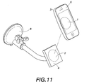
- the supporting piece 4 can be provided on a wall frame 7, a rack or a clamping seat8 in a car, or on a screen or a wall of an office.
- first and the second magnetic units 1, 2 can be respectively integrally formed; otherwise, the first and the second magnetic units 1, 2 can be respectively formed of a pluralityof sector shapes magnetic stones; otherwise, the first and the second magnetic units 1a, 2a can be formed by arrangement of a plurality of magnetic stones.
- the housing 3 and the supporting piece 4 can be respectively provided with a dented round recess 31 and a protruding block 41 for positioning when in adsorption, and the dented round recess 31 and the protruding block 41 can be taken as centers when in biased rotation for mutual rejecting and separating; the multi-poles 11, 12, 21, 22, 11a, 12a, 21a, 22a of the first magnetic unit 1, 1a and the second magnetic unit 2, 2a are arranged around their related dented round recess 31 and protruding block 41.
- the housing 3 When in practice, the housing 3 is of an arch shape which is protruding at its central area, this can reduce the friction force at the contact surface between the housing 3 and the supporting piece 4. Under the condition when the housing 3 has the enough force for adsorption, the electronic device can easily do biased rotating along the contact surface between the housing 3 and the supporting piece 4.
- the housing 3 is of an arch shape which is protruding at its central area, the housing 3 at least has its two lateral sides been provided each with an engaging rim 33 to be engaged with the two sides of the portable electronic device; otherwise, with the arch shape protruding at its central area, it allows the peripheral four sides of the housing 3 to have corresponding engaging rims 33, 34 to engage wi th the corresponding four sides of the electronic device restively.
- the housing 3 also can be made as a back cover of a portable electronic device directly, in order that the electronic device itself can have a function of the housing 3 as mentioned above.
Landscapes
- Engineering & Computer Science (AREA)
- Physics & Mathematics (AREA)
- Theoretical Computer Science (AREA)
- Signal Processing (AREA)
- Electromagnetism (AREA)
- Power Engineering (AREA)
- Computer Hardware Design (AREA)
- Human Computer Interaction (AREA)
- General Engineering & Computer Science (AREA)
- General Physics & Mathematics (AREA)
- Telephone Set Structure (AREA)
- Casings For Electric Apparatus (AREA)
Applications Claiming Priority (2)
| Application Number | Priority Date | Filing Date | Title |
|---|---|---|---|
| CN201310195212.5A CN104180131B (zh) | 2013-05-23 | 2013-05-23 | 电子装置的定位组件 |
| PCT/CN2013/000723 WO2014186916A1 (fr) | 2013-05-23 | 2013-06-21 | Ensemble de positionnement pour appareil électronique |
Publications (2)
| Publication Number | Publication Date |
|---|---|
| EP3043538A1 true EP3043538A1 (fr) | 2016-07-13 |
| EP3043538A4 EP3043538A4 (fr) | 2017-06-21 |
Family
ID=51932692
Family Applications (1)
| Application Number | Title | Priority Date | Filing Date |
|---|---|---|---|
| EP13884968.2A Withdrawn EP3043538A4 (fr) | 2013-05-23 | 2013-06-21 | Ensemble de positionnement pour appareil électronique |
Country Status (5)
| Country | Link |
|---|---|
| US (1) | US20150380139A1 (fr) |
| EP (1) | EP3043538A4 (fr) |
| CN (1) | CN104180131B (fr) |
| CA (1) | CA2912329A1 (fr) |
| WO (1) | WO2014186916A1 (fr) |
Cited By (2)
| Publication number | Priority date | Publication date | Assignee | Title |
|---|---|---|---|---|
| US11885617B2 (en) | 2018-10-31 | 2024-01-30 | Trimble Ab | Geodetic assembly with magnetic attaching arrangement |
| EP4218143A4 (fr) * | 2020-09-22 | 2024-10-30 | Balderston, Brian, Robert | Accessoire de support adaptatif pour dispositifs mobiles |
Families Citing this family (33)
| Publication number | Priority date | Publication date | Assignee | Title |
|---|---|---|---|---|
| CN104853017B (zh) * | 2015-04-21 | 2018-03-23 | 浙江吉利控股集团有限公司 | 充电宝及组合式终端设备 |
| US10164678B2 (en) | 2015-06-05 | 2018-12-25 | Huawei Technologies Co., Ltd. | Electronic product protective case |
| CN105032777B (zh) * | 2015-06-15 | 2017-12-08 | 无锡传奇科技有限公司 | 一种软胶囊检测机 |
| US9800283B2 (en) | 2015-06-17 | 2017-10-24 | Airo Collective, Inc. | Mobile device holder |
| US10774978B2 (en) * | 2015-10-29 | 2020-09-15 | Alberto Rene Somoano | Adjustable portable electronic device holder |
| CN205137013U (zh) * | 2015-11-23 | 2016-04-06 | 乐视致新电子科技(天津)有限公司 | 一种显示设备的壁挂装置及显示设备 |
| IL246291A (en) * | 2016-06-16 | 2017-07-31 | Anisfeld Ron | Means for attaching a smartphone that includes a magnetic board with opposite poles |
| US20180080598A1 (en) * | 2016-09-20 | 2018-03-22 | Apple Inc. | Counterbalanced display stand |
| US11170924B2 (en) * | 2017-03-02 | 2021-11-09 | Microsoft Technology Licensing, Llc | Computing devices, removable support devices, and methods of use |
| GB2564137A (en) * | 2017-07-04 | 2019-01-09 | Spotspot Ltd | Surface mounting device |
| CN111425716A (zh) * | 2018-05-31 | 2020-07-17 | 张旺 | 车载支架 |
| CN111412349B (zh) * | 2019-01-07 | 2021-12-03 | 深圳市鸿飞精密科技有限公司 | 电子设备及其基座固定套组 |
| US11497299B2 (en) * | 2019-06-12 | 2022-11-15 | Watchguard Video Inc. | Magnetic body-worn mounting system and method |
| GB2585139B (en) * | 2019-06-12 | 2022-03-09 | Watchguard Video Inc | Magnetic body-worn mounting system and method |
| US10836325B1 (en) * | 2019-07-30 | 2020-11-17 | Honda Motor Co., Ltd. | Removable device stand |
| CN111059442B (zh) * | 2019-12-31 | 2021-12-24 | 联想(北京)有限公司 | 一种承载装置 |
| US11330093B2 (en) | 2020-06-02 | 2022-05-10 | ohSnap, Inc. | Magnetically connectable grip and connector for electronics |
| WO2021247751A1 (fr) * | 2020-06-02 | 2021-12-09 | ohSnap, Inc. | Élément de prise et connecteur pouvant être reliés magnétiquement pour l'électronique |
| CN214177359U (zh) * | 2021-01-07 | 2021-09-10 | 深圳奇妙星球文化创意有限公司 | 电子设备支架 |
| US12531435B2 (en) | 2021-12-17 | 2026-01-20 | Annex Products Pty. Ltd. | Wireless charger mounting system |
| CN115639893A (zh) * | 2022-06-20 | 2023-01-24 | 深圳市毅荣川电子科技有限公司 | 一种便于进行拆装的电脑散热扇 |
| USD1024048S1 (en) | 2022-06-28 | 2024-04-23 | Annex Products Pty Ltd | Mounting head |
| USD1024049S1 (en) | 2022-06-28 | 2024-04-23 | Annex Products Pty Ltd | Mounting head |
| USD1087942S1 (en) | 2022-06-28 | 2025-08-12 | Annex Products Pty. Ltd. | Case for mobile electronic device |
| USD1028964S1 (en) | 2022-06-29 | 2024-05-28 | Annex Products Pty Ltd | Desk stand |
| DK181677B1 (en) * | 2022-09-05 | 2024-09-18 | Unicontrol Aps | Mounting system and method for releasably attaching a device to a mounting structure attached to a vehicle |
| US12016450B2 (en) | 2022-09-13 | 2024-06-25 | ohSnap, Inc. | Grip for portable electronic devices |
| USD1071839S1 (en) | 2023-03-10 | 2025-04-22 | Annex Products Pty. Ltd. | Battery attachment |
| CN116320120B (zh) * | 2023-05-24 | 2023-09-29 | 深圳市蓝禾技术有限公司 | 磁性连接件以及电子设备支架 |
| USD1076425S1 (en) | 2023-03-16 | 2025-05-27 | Annex Products Pty. Ltd. | Wallet attachment |
| US20250107615A1 (en) * | 2023-10-03 | 2025-04-03 | ohSnap, Inc. | Magnetic Assemblies for Grips for Portable Handheld Devices |
| FR3158093A1 (fr) * | 2024-01-05 | 2025-07-11 | Valeo Comfort And Driving Assistance | Ensemble comportant un socle d'accueil et un dispositif d'affichage |
| DE102024108165A1 (de) * | 2024-03-21 | 2025-09-25 | Fidlock Gmbh | Haltevorrichtung für ein eine Magnetanordnung aufweisendes Elektrogerät |
Family Cites Families (11)
| Publication number | Priority date | Publication date | Assignee | Title |
|---|---|---|---|---|
| JPH06127U (ja) * | 1992-06-15 | 1994-01-11 | 有限会社古山商事 | ネックレス等の止め具 |
| TW587739U (en) * | 2003-03-07 | 2004-05-11 | Tatung Co | Structure for locking a portable computer device to an expansion seat |
| ITMI20071667A1 (it) * | 2007-08-10 | 2009-02-11 | Reckitt Benckiser Nv | Supporto di erogazione per un dispensatore di sostanze erogabili, in particolare agenti di lavaggio |
| US8174347B2 (en) * | 2010-07-12 | 2012-05-08 | Correlated Magnetics Research, Llc | Multilevel correlated magnetic system and method for using the same |
| US7956712B2 (en) * | 2008-05-20 | 2011-06-07 | Cedar Ridge Research, Llc. | Correlated magnetic assemblies for securing objects in a vehicle |
| TWM349145U (en) * | 2008-09-12 | 2009-01-11 | Inventec Appliances Corp | A multi-step sliding structure for handheld device |
| US20110192857A1 (en) * | 2008-12-18 | 2011-08-11 | Wayne Philip Rothbaum | Magnetically Attached Accessories (For A Case) for a Portable Electronics Device |
| CA2745106A1 (fr) * | 2011-06-29 | 2012-12-29 | Xavier Abou Nassar | Systeme de verrouillage magnetique automatique |
| CN202713419U (zh) * | 2012-06-04 | 2013-01-30 | 富士康(昆山)电脑接插件有限公司 | 手机座 |
| CN203313551U (zh) * | 2013-05-23 | 2013-11-27 | 秀越实业股份有限公司 | 电子装置的定位组件 |
| US9019698B2 (en) * | 2013-05-30 | 2015-04-28 | Jean-Michel Thiers | Mounting system for electronic device |
-
2013
- 2013-05-23 CN CN201310195212.5A patent/CN104180131B/zh not_active Expired - Fee Related
- 2013-06-21 WO PCT/CN2013/000723 patent/WO2014186916A1/fr not_active Ceased
- 2013-06-21 CA CA2912329A patent/CA2912329A1/fr not_active Abandoned
- 2013-06-21 EP EP13884968.2A patent/EP3043538A4/fr not_active Withdrawn
- 2013-06-21 US US14/763,975 patent/US20150380139A1/en not_active Abandoned
Non-Patent Citations (1)
| Title |
|---|
| See references of WO2014186916A1 * |
Cited By (3)
| Publication number | Priority date | Publication date | Assignee | Title |
|---|---|---|---|---|
| US11885617B2 (en) | 2018-10-31 | 2024-01-30 | Trimble Ab | Geodetic assembly with magnetic attaching arrangement |
| EP4218143A4 (fr) * | 2020-09-22 | 2024-10-30 | Balderston, Brian, Robert | Accessoire de support adaptatif pour dispositifs mobiles |
| US12395201B2 (en) | 2020-09-22 | 2025-08-19 | Brian Robert Balderston | Adaptive support accessory for mobile devices |
Also Published As
| Publication number | Publication date |
|---|---|
| CA2912329A1 (fr) | 2014-11-27 |
| EP3043538A4 (fr) | 2017-06-21 |
| CN104180131B (zh) | 2016-06-01 |
| WO2014186916A1 (fr) | 2014-11-27 |
| US20150380139A1 (en) | 2015-12-31 |
| CN104180131A (zh) | 2014-12-03 |
Similar Documents
| Publication | Publication Date | Title |
|---|---|---|
| EP3043538A1 (fr) | Ensemble de positionnement pour appareil électronique | |
| US9013865B2 (en) | Electronic device and support mechanism thereof | |
| US20230389684A1 (en) | Attachment for a mobile phone case | |
| WO2016000435A1 (fr) | Support | |
| CN103162078B (zh) | 支撑架及具有该支撑架的电子装置 | |
| KR101510202B1 (ko) | 휴대폰 보호필름 구조체 | |
| EP2521350A3 (fr) | Conférence vidéo | |
| WO2022007220A1 (fr) | Vitrine d'exposition pour la vente de dispositifs terminaux électroniques | |
| US9215816B2 (en) | Stand assembly and electronic apparatus | |
| CN101877735A (zh) | 支撑结构及具该支撑结构的便携式电子装置 | |
| CN106033654A (zh) | 曲面显示器 | |
| CN212211234U (zh) | 一种直播电视 | |
| CN206012487U (zh) | 一种组合的电子设备固定支架 | |
| CN205725879U (zh) | 一种3d虚拟现实手机壳眼镜 | |
| CN205281062U (zh) | 基板支撑装置 | |
| TWI491340B (zh) | Positioning device for electronic devices | |
| TWM461976U (zh) | 電子裝置的定位組件 | |
| CN206350049U (zh) | 一种手机支架 | |
| CN210034808U (zh) | 移动终端支架 | |
| CN204044695U (zh) | 屏幕可在竖直平面内转动的显示器 | |
| GB2503749A (en) | Tablet computer and smartphone holder that can rotate relative to the mount | |
| CN104742085A (zh) | 吸盘 | |
| KR102371463B1 (ko) | 모바일 단말기 케이스 | |
| CN205278727U (zh) | 一种具备多种可更换吸附头的手机及平板电脑新型支架 | |
| KR20120004135U (ko) | 차량용 휴대단말기 지지 장치 |
Legal Events
| Date | Code | Title | Description |
|---|---|---|---|
| PUAI | Public reference made under article 153(3) epc to a published international application that has entered the european phase |
Free format text: ORIGINAL CODE: 0009012 |
|
| 17P | Request for examination filed |
Effective date: 20160324 |
|
| AK | Designated contracting states |
Kind code of ref document: A1 Designated state(s): AL AT BE BG CH CY CZ DE DK EE ES FI FR GB GR HR HU IE IS IT LI LT LU LV MC MK MT NL NO PL PT RO RS SE SI SK SM TR |
|
| AX | Request for extension of the european patent |
Extension state: BA ME |
|
| DAX | Request for extension of the european patent (deleted) | ||
| A4 | Supplementary search report drawn up and despatched |
Effective date: 20170524 |
|
| RIC1 | Information provided on ipc code assigned before grant |
Ipc: H04M 1/11 20060101AFI20170518BHEP Ipc: H01F 7/02 20060101ALI20170518BHEP Ipc: H04M 1/04 20060101ALI20170518BHEP |
|
| STAA | Information on the status of an ep patent application or granted ep patent |
Free format text: STATUS: REQUEST FOR EXAMINATION WAS MADE |
|
| STAA | Information on the status of an ep patent application or granted ep patent |
Free format text: STATUS: THE APPLICATION IS DEEMED TO BE WITHDRAWN |
|
| 18D | Application deemed to be withdrawn |
Effective date: 20190103 |