EP3043545A1 - Taschenscanner - Google Patents
Taschenscanner Download PDFInfo
- Publication number
- EP3043545A1 EP3043545A1 EP15150177.2A EP15150177A EP3043545A1 EP 3043545 A1 EP3043545 A1 EP 3043545A1 EP 15150177 A EP15150177 A EP 15150177A EP 3043545 A1 EP3043545 A1 EP 3043545A1
- Authority
- EP
- European Patent Office
- Prior art keywords
- pcb
- optical engine
- assembly
- engine module
- cover
- Prior art date
- Legal status (The legal status is an assumption and is not a legal conclusion. Google has not performed a legal analysis and makes no representation as to the accuracy of the status listed.)
- Withdrawn
Links
- 230000003287 optical effect Effects 0.000 claims abstract description 63
- 238000004891 communication Methods 0.000 claims description 9
- 230000001681 protective effect Effects 0.000 claims description 4
- 239000011521 glass Substances 0.000 claims description 3
- 238000000034 method Methods 0.000 claims description 3
- 230000000149 penetrating effect Effects 0.000 claims description 2
- IUYHQGMDSZOPDZ-UHFFFAOYSA-N 2,3,4-trichlorobiphenyl Chemical compound ClC1=C(Cl)C(Cl)=CC=C1C1=CC=CC=C1 IUYHQGMDSZOPDZ-UHFFFAOYSA-N 0.000 description 16
- ONNCPBRWFSKDMQ-UHFFFAOYSA-N 2,3',5-trichlorobiphenyl Chemical compound ClC1=CC=CC(C=2C(=CC=C(Cl)C=2)Cl)=C1 ONNCPBRWFSKDMQ-UHFFFAOYSA-N 0.000 description 6
- XBBZAULFUPBZSP-UHFFFAOYSA-N 2,4-dichloro-1-(3-chlorophenyl)benzene Chemical compound ClC1=CC(Cl)=CC=C1C1=CC=CC(Cl)=C1 XBBZAULFUPBZSP-UHFFFAOYSA-N 0.000 description 5
- CJDNEKOMKXLSBN-UHFFFAOYSA-N 1-chloro-3-(4-chlorophenyl)benzene Chemical compound C1=CC(Cl)=CC=C1C1=CC=CC(Cl)=C1 CJDNEKOMKXLSBN-UHFFFAOYSA-N 0.000 description 4
- LVROLHVSYNLFBE-UHFFFAOYSA-N 2,3,6-trichlorobiphenyl Chemical compound ClC1=CC=C(Cl)C(C=2C=CC=CC=2)=C1Cl LVROLHVSYNLFBE-UHFFFAOYSA-N 0.000 description 4
- QHZSDTDMQZPUKC-UHFFFAOYSA-N 3,5-dichlorobiphenyl Chemical compound ClC1=CC(Cl)=CC(C=2C=CC=CC=2)=C1 QHZSDTDMQZPUKC-UHFFFAOYSA-N 0.000 description 3
- 150000003071 polychlorinated biphenyls Chemical class 0.000 description 2
- VAHKBZSAUKPEOV-UHFFFAOYSA-N 1,4-dichloro-2-(4-chlorophenyl)benzene Chemical compound C1=CC(Cl)=CC=C1C1=CC(Cl)=CC=C1Cl VAHKBZSAUKPEOV-UHFFFAOYSA-N 0.000 description 1
- 238000005516 engineering process Methods 0.000 description 1
- 238000005286 illumination Methods 0.000 description 1
Images


Classifications
-
- H—ELECTRICITY
- H04—ELECTRIC COMMUNICATION TECHNIQUE
- H04N—PICTORIAL COMMUNICATION, e.g. TELEVISION
- H04N1/00—Scanning, transmission or reproduction of documents or the like, e.g. facsimile transmission; Details thereof
- H04N1/04—Scanning arrangements, i.e. arrangements for the displacement of active reading or reproducing elements relative to the original or reproducing medium, or vice versa
- H04N1/10—Scanning arrangements, i.e. arrangements for the displacement of active reading or reproducing elements relative to the original or reproducing medium, or vice versa using flat picture-bearing surfaces
- H04N1/107—Scanning arrangements, i.e. arrangements for the displacement of active reading or reproducing elements relative to the original or reproducing medium, or vice versa using flat picture-bearing surfaces with manual scanning
- H04N1/1071—Scanning arrangements, i.e. arrangements for the displacement of active reading or reproducing elements relative to the original or reproducing medium, or vice versa using flat picture-bearing surfaces with manual scanning using a folded light path
-
- H—ELECTRICITY
- H04—ELECTRIC COMMUNICATION TECHNIQUE
- H04N—PICTORIAL COMMUNICATION, e.g. TELEVISION
- H04N1/00—Scanning, transmission or reproduction of documents or the like, e.g. facsimile transmission; Details thereof
- H04N1/00519—Constructional details not otherwise provided for, e.g. housings, covers
- H04N1/00522—Reducing apparatus footprint, e.g. wall-mounted or vertically arranged apparatus
-
- H—ELECTRICITY
- H04—ELECTRIC COMMUNICATION TECHNIQUE
- H04N—PICTORIAL COMMUNICATION, e.g. TELEVISION
- H04N1/00—Scanning, transmission or reproduction of documents or the like, e.g. facsimile transmission; Details thereof
- H04N1/04—Scanning arrangements, i.e. arrangements for the displacement of active reading or reproducing elements relative to the original or reproducing medium, or vice versa
- H04N1/10—Scanning arrangements, i.e. arrangements for the displacement of active reading or reproducing elements relative to the original or reproducing medium, or vice versa using flat picture-bearing surfaces
- H04N1/107—Scanning arrangements, i.e. arrangements for the displacement of active reading or reproducing elements relative to the original or reproducing medium, or vice versa using flat picture-bearing surfaces with manual scanning
Definitions
- the present invention relates to a scanner, and more particularly to a pocket scanner.
- a traditional handheld scanner where the optical elements are arranged in a line, scans a horizontal line of an original in a same time or in a same program. Therefore, the length of the line where the optical elements are must be longer than that of the horizontal line of the original. As a result, the appearance of the handheld scanner is too long to carry inconveniently.
- a traditional mouse-shaped scanner has two-dimensional array type optical elements and position sensors.
- the mouse-shaped scanner firstly converts the original into a plurality of small frame images and then joints the plurality of small frame images into a complete digital image.
- the mouse-shaped scanner achieves a greatly shortened length, but still its appearance is limited by the length, width and height of a mouse.
- the position of an optical engine module and a PCB assembly in the mouse-shaped scanner has a crucial influence on appearance size of the mouse.
- the present invention is to provide a pocket scanner direct at the shortage of existing technology.
- the pocket scanner has an advantage of small size for the convenience of carrying.
- an object of the present invention is to provide a pocket scanner for converting an original to a digital image.
- the pocket scanner includes an optical engine module, a PCB assembly and a cover assembly.
- the optical engine module includes a frame. A bottom of the frame defines an elongated scanning window. The long side of the scanning window is parallel with the long side of the bottom of the frame.
- a top of the frame of the optical engine module is designed with a slant plane slantwise facing the scanning window.
- the PCB assembly includes a control PCB, a bracket and a battery module. The control PCB is located above the optical engine module and perpendicular with the scanning window. A bottom of the control PCB is designed with a slant edge corresponding to the slant plane of the optical engine module.
- the slant edge of the control PCB is against the slant plane of the optical engine module when assembly.
- the bracket is mounted to a side of the control PCB and above the optical engine module. One side of the bracket back to the control PCB is opened with a receiving cavity.
- the battery module is received in the receiving cavity and electrically connected to the control PCB.
- the cover assembly encloses the optical engine module and the PCB assembly.
- the cover assembly includes a bottom cover, a top cover and two side covers.
- the optical engine module is mounted on the bottom cover.
- the top cover covers on the bottom cover.
- the two side covers are respectively covered to two sides of the bottom cover and the top cover.
- the bottom cover is opened with a scanning opening corresponding to the scanning window of the optical engine module.
- a glass is equipped in the scanning opening.
- the optical engine module is electrically connected to the PCB assembly and scans the original through the scanning opening and the scanning window to obtain image information.
- the control PCB of the PCB assembly receives and processes
- the top of the frame of the optical engine module is designed with the slant plane
- the bottom of the control PCB is designed with the slant edge corresponding to the slant plane of the optical engine module.
- the slant edge of the control PCB is against the slant plane of the optical engine module to realize a minimum of occupied space in the frame when assembly. Therefore, the pocket scanner has an advantage of small size for the convenience of carrying.
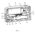
- an embodiment of the present invention is embodied in a pocket scanner 100 for converting an original to a digital image.
- the pocket scanner 100 includes an optical engine module 10, a PCB assembly 20 and a cover assembly 30.
- the optical engine module 10 is electrically connected to the PCB assembly 20.
- the optical engine module 10 includes a frame 11.
- a bottom of the frame 11 defines an elongated scanning window 113.
- the long side of the scanning window 113 is parallel with the long side of the bottom of the frame 11.
- a top of the frame 11 of the optical engine module 10 is designed with a slant plane 111 slantwise facing the scanning window 113.
- the slant plane 111 of the optical engine module 10 is opened with a through slot 112 penetrating through the slant plane 111.
- the optical engine module 10 further includes a retroreflector 12 buckled in the through slot 112 of the slant plane 111 and forming a high portion 121 and a low portion 122.
- the retroreflector 12 is used to change the path of light.
- An inner side of the frame 11 facing the high portion 121 of the retroreflector 12 is equipped with an image PCB 13.
- the image PCB 13 is electrically connected to the PCB assembly 20.
- An inner side of the image PCB 13 facing the retroreflector 12 is equipped with an image sensor 131 and an image lens 132 mounted outside the image sensor 131.
- the image lens 132 is used to focus image information from the original to the image sensor 131 through the scanning window 113 and then by the reflection of the retroreflector 12.
- the image sensor 131 changes the image information into voltage signals and sends the voltage signals to the PCB assembly 20.
- the PCB assembly 20 converts the voltages signals to the digital image.
- the light PCB 14 is electrically connected to the PCB assembly 20.
- An inner side of the light PCB 14 is equipped with a plurality of light sources 15.
- the light sources 15 illuminate an inner space of the frame 11 and partly illuminate on the original through the scanning window 113 of the frame 11 of the optical engine module 10.
- the light sources 15 include three Light Emitting Diodes. The illumination distribution depends on the location distribution of the three Light Emitting Diodes.
- the PCB assembly 20 includes a control PCB 21, a bracket 22 and a battery module 23.
- the control PCB 21 is located above the optical engine module 10 and perpendicular with the scanning window 113.
- a bottom of the control PCB 21 is designed with a slant edge 211 corresponding to the slant plane 111 of the optical engine module 10.
- the slant edge 211 of the control PCB 21 is against the slant plane 111 of the optical engine module 10 to realize a minimum of occupied space in the frame 11 when assembly.
- the bracket 22 is mounted to a side of the control PCB 21 and above the optical engine module 10. One side of the bracket 22 back to the control PCB 21 is opened with a receiving cavity 221.
- the battery module 23 is received in the receiving cavity 221 and electrically connected to the control PCB 21.
- the battery module 23 provides voltage to the control PCB 21 for working.
- the battery module 23 is a rechargeable battery module.
- the PCB assembly 20 further includes a button PCB 24 horizontally mounted on the bracket 22 and the optical engine module 10 and far away from the battery module 23.
- the button PCB 24 is electrically connected to the control PCB 21.
- a scanning switch 241 and at least one indicator light 242 are mounted on a top face of the button PCB 24.
- the PCB assembly 20 further includes a wireless PCB 25.
- the wireless PCB 25 is mounted on an outside wall of the optical engine module 10 adjacent to the battery module 23.
- the wireless PCB 25 is perpendicular with the scanning window 113.
- the wireless PCB 25 is electrically connected to the control PCB 21.
- the wireless PCB 25 is equipped with a wireless transmit module 251 for exchanging data with external equipment.
- the wireless transmit module 251 is a bluetooth module.
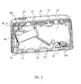
- the cover assembly 30 encloses the optical engine module 10 and the PCB assembly 20.
- the cover assembly 30 includes a bottom cover 31, a top cover 32 and two side covers 33.
- the optical engine module 10 is mounted on the bottom cover 31.
- the bottom cover 31 is opened with a scanning opening 311 corresponding to the scanning window 113 of the optical engine module 10.
- the optical engine module 10 scans the original through the scanning opening 311 and the scanning window 113 to obtain the image information of the original.
- the control PCB 21 of the PCB assembly 20 receives and processes the image information into the digital image.
- a glass 312 is equipped in the scanning opening 311 to prevent other objects into the optical engine module 10.
- the PCB assembly 20 further includes a laser PCB 26 electrically connected to the control PCB 21.
- the laser PCB 26 is horizontally mounted on the bottom cover 31 under the battery module 23 and adjacent to the optical engine module 10.
- the laser PCB 26 is equipped with a laser sensor 261 and a laser lens 263 mounted outside the laser sensor 261 under the laser PCB 26.
- a power switch 262 is mounted on a bottom face of the laser PCB 26.
- the bottom cover 31 is opened with a laser hole 313 corresponding to the laser lens 312 of the laser PCB 26.
- the laser sensor 311 of the laser PCB 31 collects some information about the original through the laser hole 313 and the laser lens 312, and sends the some information to the control PCB 21 for providing an auxiliary position for the image information obtained by the optical engine module 10.
- the bottom cover 31 is equipped with a power button 314 corresponding to the power switch 262.
- the power button 314 sheathes outside of the power switch 262.
- the top cover 32 of the cover assembly 30 covers on the bottom cover 31.
- the top cover 32 of the cover assembly 30 is equipped with a scanning button 321 covering the scanning switch 241 and one of the at least one indicator light 242 of the button PCB 24 of the PCB assembly 20.
- pressing the scanning button 321 can trigger the scanning switch 241 to drive the pocket scanner 100 to start scanning.
- the one of the at least one indicator light 242 under the scanning button 321 is lit to indicate the pocket scanner 100 is scanning.
- the scanning button 321 is movably mounted in the top cover 32 of the cover assembly 30 and located above the bracket 22 of the PCB assembly 20.
- the top cover 32 of the cover assembly 30 is further equipped with a light pipe 322.
- the light pipe 322 is located over another one of the at least one indicator light 242. When exchanging the data or charging the battery module 23, the another one of the at least one indicator light 242 under the light pipe 322 is lit or twinkles to indicate the relative working status.
- the control PCB 21 of the PCB assembly 20 is equipped with a communication interface 212.
- the pocket scanner 100 can exchange the data with the external equipment through the communication interface 212.
- the top cover 32 of the cover assembly 30 is opened with a through hole 323 corresponding to the communication interface 212.
- the communication interface 212 is received in the through hole 323.
- the top cover 32 of the cover assembly 30 is further equipped with a protective cover 324 corresponding to the through hole 323.
- the protective cover 324 is buckled in the through hole 323 to cover the communication interface 212.
- the two side covers 33 are respectively covered to two sides of the bottom cover 31 and the top cover 32.
- the two side covers 33 of the cover assembly 30 are openable for the convenience of changing the battery module 23.
- all of the PCBs are equipped with connectors 27 which are electrically connected through connecting lines 28 to realize electrical connection among the PCBs.
- the top of the frame 11 of the optical engine module 10 is designed with the slant plane 111
- the bottom of the control PCB 21 is designed with the slant edge 211 corresponding to the slant plane 111 of the optical engine module 10.
- the slant edge 211 of the control PCB 21 is against the slant plane 111 of the optical engine module 10 to realize a minimum of occupied space in the frame 11 when assembly. Therefore, the pocket scanner 100 has an advantage of small size for the convenience of carrying.
Landscapes
- Engineering & Computer Science (AREA)
- Multimedia (AREA)
- Signal Processing (AREA)
- Facsimile Scanning Arrangements (AREA)
Priority Applications (1)
| Application Number | Priority Date | Filing Date | Title |
|---|---|---|---|
| EP15150177.2A EP3043545A1 (de) | 2015-01-06 | 2015-01-06 | Taschenscanner |
Applications Claiming Priority (1)
| Application Number | Priority Date | Filing Date | Title |
|---|---|---|---|
| EP15150177.2A EP3043545A1 (de) | 2015-01-06 | 2015-01-06 | Taschenscanner |
Publications (1)
| Publication Number | Publication Date |
|---|---|
| EP3043545A1 true EP3043545A1 (de) | 2016-07-13 |
Family
ID=52302119
Family Applications (1)
| Application Number | Title | Priority Date | Filing Date |
|---|---|---|---|
| EP15150177.2A Withdrawn EP3043545A1 (de) | 2015-01-06 | 2015-01-06 | Taschenscanner |
Country Status (1)
| Country | Link |
|---|---|
| EP (1) | EP3043545A1 (de) |
Citations (3)
| Publication number | Priority date | Publication date | Assignee | Title |
|---|---|---|---|---|
| US4906843A (en) * | 1987-12-31 | 1990-03-06 | Marq Technolgies | Combination mouse, optical scanner and digitizer puck |
| EP1143697A2 (de) * | 2000-04-03 | 2001-10-10 | Hewlett-Packard Company | Optische Abtastvorrichtung |
| US20110234497A1 (en) * | 2010-03-25 | 2011-09-29 | Dacuda Ag | Computer peripheral for scanning |
-
2015
- 2015-01-06 EP EP15150177.2A patent/EP3043545A1/de not_active Withdrawn
Patent Citations (3)
| Publication number | Priority date | Publication date | Assignee | Title |
|---|---|---|---|---|
| US4906843A (en) * | 1987-12-31 | 1990-03-06 | Marq Technolgies | Combination mouse, optical scanner and digitizer puck |
| EP1143697A2 (de) * | 2000-04-03 | 2001-10-10 | Hewlett-Packard Company | Optische Abtastvorrichtung |
| US20110234497A1 (en) * | 2010-03-25 | 2011-09-29 | Dacuda Ag | Computer peripheral for scanning |
Non-Patent Citations (1)
| Title |
|---|
| C SMITH: "Meet PocketScan", 19 June 2014 (2014-06-19), XP002740826, Retrieved from the Internet <URL:http://bgr.com/2014/06/19/kickstarter-pocketscan-portable-scanner/> [retrieved on 20150611] * |
Similar Documents
| Publication | Publication Date | Title |
|---|---|---|
| US6628335B1 (en) | Image capture module and image capture apparatus for inputting shape of object on three dimensional space | |
| US11516455B2 (en) | Electronic device and method for controlling the same | |
| KR102426510B1 (ko) | 이동 단말기 | |
| CN106412166B (zh) | 终端的壳体组件及终端 | |
| US20210188436A1 (en) | Photographing device, gimble camera, and unmanned aerial vehicle | |
| US20170019700A1 (en) | Mobile real-time video recording and transmission mirror/hairbrush/lipstick | |
| KR20190127184A (ko) | 전자장치의 관로 구조 및 이를 포함하는 전자장치 | |
| CN106778492B (zh) | 指纹模组、移动终端及指纹采集方法 | |
| WO2019227974A1 (zh) | 电子组件和电子装置 | |
| EP3502951B1 (de) | Ergonomisches tragbares datenerfassungsendgerät | |
| US9288350B1 (en) | Pocket scanner | |
| EP3043545A1 (de) | Taschenscanner | |
| US20210036468A1 (en) | Power supply device | |
| CN211505870U (zh) | 一种接收器、深度摄像模组和电子设备 | |
| KR20170026002A (ko) | 3차원 깊이 카메라 모듈 및 이를 구비하는 이동 단말기 | |
| EP3787275B1 (de) | Abbildungskomponente, elektronische komponente, elektronische vorrichtung und verfahren zur steuerung einer elektronischen vorrichtung | |
| CN204989618U (zh) | 手持式多功能工业内窥镜检视装置 | |
| JP6104860B2 (ja) | 電気機器のケーブル保持構造 | |
| JP2019074972A (ja) | ウエアラブル型の測定装置 | |
| EP3574632B1 (de) | Sensorkombination | |
| CN206292809U (zh) | 指纹模组及移动终端 | |
| CN204244333U (zh) | 便携式扫描仪 | |
| JP7729053B2 (ja) | 測色装置 | |
| CN211656219U (zh) | 一种摄像装置 | |
| CN213092317U (zh) | 翻译设备 |
Legal Events
| Date | Code | Title | Description |
|---|---|---|---|
| PUAI | Public reference made under article 153(3) epc to a published international application that has entered the european phase |
Free format text: ORIGINAL CODE: 0009012 |
|
| 17P | Request for examination filed |
Effective date: 20150302 |
|
| AK | Designated contracting states |
Kind code of ref document: A1 Designated state(s): AL AT BE BG CH CY CZ DE DK EE ES FI FR GB GR HR HU IE IS IT LI LT LU LV MC MK MT NL NO PL PT RO RS SE SI SK SM TR |
|
| AX | Request for extension of the european patent |
Extension state: BA ME |
|
| STAA | Information on the status of an ep patent application or granted ep patent |
Free format text: STATUS: THE APPLICATION IS DEEMED TO BE WITHDRAWN |
|
| 18D | Application deemed to be withdrawn |
Effective date: 20170114 |