EP3043982B1 - Dispositif et procédé permettant de comprimer des contenants en matière plastique sans formation d'une rupture blanche - Google Patents
Dispositif et procédé permettant de comprimer des contenants en matière plastique sans formation d'une rupture blanche Download PDFInfo
- Publication number
- EP3043982B1 EP3043982B1 EP14766423.9A EP14766423A EP3043982B1 EP 3043982 B1 EP3043982 B1 EP 3043982B1 EP 14766423 A EP14766423 A EP 14766423A EP 3043982 B1 EP3043982 B1 EP 3043982B1
- Authority
- EP
- European Patent Office
- Prior art keywords
- container
- holding device
- holding
- containers
- compressed
- Prior art date
- Legal status (The legal status is an assumption and is not a legal conclusion. Google has not performed a legal analysis and makes no representation as to the accuracy of the status listed.)
- Active
Links
Images



Classifications
-
- B—PERFORMING OPERATIONS; TRANSPORTING
- B30—PRESSES
- B30B—PRESSES IN GENERAL
- B30B9/00—Presses specially adapted for particular purposes
- B30B9/32—Presses specially adapted for particular purposes for consolidating scrap metal or for compacting used cars
- B30B9/321—Presses specially adapted for particular purposes for consolidating scrap metal or for compacting used cars for consolidating empty containers, e.g. cans
-
- B—PERFORMING OPERATIONS; TRANSPORTING
- B29—WORKING OF PLASTICS; WORKING OF SUBSTANCES IN A PLASTIC STATE IN GENERAL
- B29C—SHAPING OR JOINING OF PLASTICS; SHAPING OF MATERIAL IN A PLASTIC STATE, NOT OTHERWISE PROVIDED FOR; AFTER-TREATMENT OF THE SHAPED PRODUCTS, e.g. REPAIRING
- B29C49/00—Blow-moulding, i.e. blowing a preform or parison to a desired shape within a mould; Apparatus therefor
- B29C49/42—Component parts, details or accessories; Auxiliary operations
- B29C49/4273—Auxiliary operations after the blow-moulding operation not otherwise provided for
-
- B—PERFORMING OPERATIONS; TRANSPORTING
- B29—WORKING OF PLASTICS; WORKING OF SUBSTANCES IN A PLASTIC STATE IN GENERAL
- B29C—SHAPING OR JOINING OF PLASTICS; SHAPING OF MATERIAL IN A PLASTIC STATE, NOT OTHERWISE PROVIDED FOR; AFTER-TREATMENT OF THE SHAPED PRODUCTS, e.g. REPAIRING
- B29C69/00—Combinations of shaping techniques not provided for in a single one of main groups B29C39/00 - B29C67/00, e.g. associations of moulding and joining techniques; Apparatus therefore
- B29C69/02—Combinations of shaping techniques not provided for in a single one of main groups B29C39/00 - B29C67/00, e.g. associations of moulding and joining techniques; Apparatus therefore of moulding techniques only
- B29C69/025—Deforming articles in a simpler intermediate shape without internal stresses for packaging transporting or storage and reshaping and fixing the original configuration on the place of use
-
- B—PERFORMING OPERATIONS; TRANSPORTING
- B30—PRESSES
- B30B—PRESSES IN GENERAL
- B30B15/00—Details of, or accessories for, presses; Auxiliary measures in connection with pressing
- B30B15/34—Heating or cooling presses or parts thereof
-
- B—PERFORMING OPERATIONS; TRANSPORTING
- B29—WORKING OF PLASTICS; WORKING OF SUBSTANCES IN A PLASTIC STATE IN GENERAL
- B29B—PREPARATION OR PRETREATMENT OF THE MATERIAL TO BE SHAPED; MAKING GRANULES OR PREFORMS; RECOVERY OF PLASTICS OR OTHER CONSTITUENTS OF WASTE MATERIAL CONTAINING PLASTICS
- B29B17/00—Recovery of plastics or other constituents of waste material containing plastics
- B29B17/04—Disintegrating plastics, e.g. by milling
-
- B—PERFORMING OPERATIONS; TRANSPORTING
- B29—WORKING OF PLASTICS; WORKING OF SUBSTANCES IN A PLASTIC STATE IN GENERAL
- B29L—INDEXING SCHEME ASSOCIATED WITH SUBCLASS B29C, RELATING TO PARTICULAR ARTICLES
- B29L2031/00—Other particular articles
- B29L2031/70—Agricultural usage or equipment
- B29L2031/7002—Agricultural usage or equipment for fishing
-
- B—PERFORMING OPERATIONS; TRANSPORTING
- B29—WORKING OF PLASTICS; WORKING OF SUBSTANCES IN A PLASTIC STATE IN GENERAL
- B29L—INDEXING SCHEME ASSOCIATED WITH SUBCLASS B29C, RELATING TO PARTICULAR ARTICLES
- B29L2031/00—Other particular articles
- B29L2031/712—Containers; Packaging elements or accessories, Packages
- B29L2031/7158—Bottles
-
- Y—GENERAL TAGGING OF NEW TECHNOLOGICAL DEVELOPMENTS; GENERAL TAGGING OF CROSS-SECTIONAL TECHNOLOGIES SPANNING OVER SEVERAL SECTIONS OF THE IPC; TECHNICAL SUBJECTS COVERED BY FORMER USPC CROSS-REFERENCE ART COLLECTIONS [XRACs] AND DIGESTS
- Y02—TECHNOLOGIES OR APPLICATIONS FOR MITIGATION OR ADAPTATION AGAINST CLIMATE CHANGE
- Y02W—CLIMATE CHANGE MITIGATION TECHNOLOGIES RELATED TO WASTEWATER TREATMENT OR WASTE MANAGEMENT
- Y02W30/00—Technologies for solid waste management
- Y02W30/50—Reuse, recycling or recovery technologies
- Y02W30/62—Plastics recycling; Rubber recycling
Definitions
- the present invention relates to an apparatus and method for compressing plastic containers.
- such devices and methods are known. These are usually used to compress filled containers and in this way to squeeze liquid from these containers.
- the applicant has recently moved to a different procedure. Especially in the production of large containers, the problem arises that during transport very high volumes or weights must be transported. Therefore, in a still unpublished patent application, the Applicant has proposed the concept of first producing plastic containers, for example by a blow molding process, then compressing them in an empty state, palletizing the compressed containers and transporting these pallets to a bottler. This can then expand the containers and fill with liquid, whereby the filling itself can expand the container again.
- the WO 2013/124485 A shows a device according to the preamble of claim 1 and a method according to the preamble of claim 11 for removing liquids from deformable containers.
- the device has a first and a second holding device.
- the first holding device holds a first and the second holding means a second portion of the container, wherein the portions are spaced from each other.
- the container arranged therebetween can be deformed.
- the internal volume is reduced.
- a removal device is provided which has a flow connection to the interior of the container and via which liquid in the container can be removed as a result of compression of the container.
- the device further comprises a control device which controls the relative movement of a holding device relative to the other holding device or the removal of the liquid via the removal device in dependence on an internal pressure within the container.
- the US 5 292 242 A discloses an apparatus for folding an upright container into a compact, stackable embodiment, the container having a bottom wall, side walls having at least upper, lower and middle annular stepped portions, and a top wall including a spout opening. Furthermore, the device comprises means for supporting and holding the container, wherein two opposing elements are arranged, which are designed to be movable relative to each other. One of the elements is designed to support the bottom portion of the container. In addition, a conveyor or transport means may be provided, which supplies a plurality of containers of the folding device.
- the present invention is therefore based on the one hand to facilitate the decrease of the compressed containers from the stamp or the holding device on the one hand and on the other hand also to reduce the risk of the occurrence of white fractures and preferably to improve the stackability of the containers.
- An inventive device for compressing plastic containers has a first holding device which is suitable for holding a first region of a container to be emptied. Furthermore, the device has a second holding device, which is suitable for holding and / or supporting a second region of the container to be emptied, wherein the second region is spaced from the first region. Furthermore, the device has a movement device which is adapted to move the first holding device to the second holding device in order to compress the container located between the first holding device and the second holding device.
- the first holding device has a cross section which is smaller than a cross section of the container to be compressed, so that the first holding device with the held by the first holding means first portion of the container in another portion of the container to form a respect to a longitudinal direction of the container circumferential fold is insertable.
- a stop element is provided on the first holding device, which contacts the folding position in a predetermined relative position of the first holding device with respect to the second holding device and the device has a pressure generating device, which at least temporarily acts on an interior of the container to be compressed during its compression with an internal pressure, which lies above the outer pressure around the container.
- the fold is a curl fold. In the following, therefore, instead of the term folding point also the term curl fold is used.
- the first holding device is designed as a punch element, which advantageously rests flat against a wall region of the container to be compressed during the compression process.
- This area concerns the formation of kinks and wrinkles during the compression process is prevented.
- only such a folding point should arise during the compression process.
- an opening region of the container can lie flat against the first holding device and this can displace this entire mouth region of the container into the bottom region of the container.
- the first holding device has a circular cross-section.
- the first holding device advantageously also has a receiving space for receiving the actual mouth of the container.
- the mouth is preferably a region of the container which has not been stretched in the case of a possibly preceding blow molding process.
- This mouth can also have a thread for attaching a closure, in particular an external thread.
- an outer contour of the first holding device is adapted to a contour of the container resulting from this compression of the container in order, as mentioned, to prevent the formation of kinks and breaks.
- a curvature on an outer surface is adapted to a curvature of the mouth region of the container.
- the fold rolls upwardly with respect to the holder (which may also be referred to as a punch).
- the holder which may also be referred to as a punch.
- the fold is preferably pressed against the stop element or an upper stop and preferably pressed by a radius on the holding device slightly outward.
- the holding device is such, or has such a shape that when compressing the container, an issuing or outward urging of the fold relative to a radial direction of the container and preferably also with respect to a direction perpendicular to a longitudinal direction of the container causes.
- the fold is also formed so that the containers can be stacked easier overall.
- the stop element is circumferentially formed with respect to a longitudinal direction of the holding device and preferably also with respect to the longitudinal direction of the container to be compressed. In this way, a treatment of the fold along its entire circumferential direction is possible.
- the stop element may be formed as a projection extending at least partially and preferably completely around the holding device, this projection extending at least also in a radial direction of the first holding device and being in the radial direction to the feed direction in which the first holding device second holding device is delivered, is vertical.
- the first holding device has a transition section, in which a cross section of the first holding device continuously widens.
- this transition section is provided such that it widens in a direction away from the container to be compressed in its longitudinal direction.
- This transition section is preferably designed such that it causes the said widening of the fold.
- this extension is continuous.
- the transition section also has a curved course in its cross section.
- a section with a constant cross section adjoins this transition section in the direction of the container.
- a cross section of the first holding device in the said transition section widens by at most 20%, preferably by at most 10%, preferably by at most 5% (based on the section with the constant cross section adjoining this transition section).
- a cross section of the first holding device widens in the said transition section by at least 0.5%, preferably by at least 1%, preferably by at least 3%, preferably by at least 5% (based on the section with the constant cross section adjoining this transition section).
- the longitudinal direction of the container is preferably also an axis of symmetry of the container, which particularly preferably leads from the mouth of the container to its bottom.
- the longitudinal direction of the container to be compressed also corresponds to the feed direction in which the first holding device is delivered to the second holding device.
- the container is compressed in an upright state.
- the stop element can connect to this transition section or even be formed by this transition section.
- the stop element is arranged on the first holding device via a transition section and this transition section is a curved section and in particular a radially outwardly curved section or a section which, as mentioned above, widens radially outward ,
- the holding device has a tempering device for tempering at least a portion of the first holding device. In particular, an area of the abovementioned stop is thus heated. So that the folding point remains in this outwardly oriented position even after the unloading or venting of the compressed container, it is proposed here that the holding device is tempered in particular in the region of the said stop element. This Applicant was able to determine that a temperature control in a range between 40 ° C and 80 ° C, is sufficient.
- this tempering device is used for tempering at least a portion of the stop element, in order in this way also to heat a surface of the holding device, which comes into contact with the fold.
- the pressure-generating device has a closing element, which at least partially closes an opening of the container to be compressed, so as to allow a controlled and / or reduced escape of air from the container during its compression.
- a throttle element can be provided, which allows only limited leakage of air during compression, so that a certain internal pressure is maintained in the container.
- a valve element is arranged in the closing element.
- This may be, for example, a valve which opens automatically from a certain pressure, so as to prevent the emergence of excessive pressures within the container during its compression.
- This application of an overpressure is difficult to understand at first glance, since this higher pressure also increases the force necessary for compressing.
- the Applicant has found, however, that this pressurization also affects the fold or stabilizes it against kinking and, moreover, easier removal of the container from the holding device is achieved.
- the first holding device protrudes into the container in at least one compression state.
- the holding device (or a region thereof) also has at least one section which projects at least temporarily into a turned-over section of the container to be compressed.
- the holding device is advantageous completely surrounded in its circumferential direction in at least one compression state of two superimposed wall portions of the container.
- the device has a stripping device and / or removal device in order to strip a compressed container from the first holding device.
- This can be a stripping device which is integrated, for example, in the first holding device and which pushes the container out of the holding device via its mouth.
- a stripping device is provided outside of the first holding device, and which contacts the container at its fold and thus strikes.
- the stop element can also serve as a stripping element at the same time.
- the removal device can be designed as a displaceable body and in particular as a displaceable in the feed direction body which presses on the mouth or the mouth edge of the container in order to push it away from the first holding device.
- the device has a carrier, on which a plurality of holding devices are arranged. In this way, it is preferably possible to compress several containers simultaneously.
- the device has a transport device which supplies the plastic containers to the first holding devices.
- this transport device can transport the containers in a transport direction, which is preferably perpendicular to a direction of movement of the first holding device with respect to the second holding device.
- the present invention is further directed to a method for compressing containers according to claim 11.
- plastic containers are first provided and then compressed these plastic containers.
- a first holding device holds a first region of a container to be compressed and a second holding device holds a second region of the container to be compressed, wherein the second region is spaced from the first region.
- a moving device moves the first holding device to the second holding device in a feed direction to the between to compress the first holding device and the second holding device located container.
- the first holding device with the first region of the container held by the first holding device is introduced into a further section of the container with the formation of a fold which revolves with respect to a longitudinal direction of the container.
- the folding position is contacted at least temporarily during compression with a stop element provided on the first holding device in a predetermined relative position of the first holding device with respect to the second holding device and a pressure generating device acts on an interior of the container to be compressed at least temporarily during its compression with an internal pressure over the expression existing around the container, the first holding device having a tempering device for tempering at least a portion of the first holding device.
- This is advantageously an overpressure of at least 0.5 bar.
- the container is already pre-tensioned with a predetermined pressure above the ambient pressure prior to compression.
- a pressure is provided which is at least 0.5 bar above the atmospheric pressure.
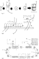
- Fig. 1 shows an illustration of the method for producing the compressed containers. It is initially assumed that a plastic preform 5, which is transformed by means of a forming device, such as a stretch blow molding machine to the container 10. In a further method step, this reshaped container, in particular compressed with the device according to the invention, such that an opening region of the plastic container is inserted in a bottom region of the plastic container.
- Reference numeral 10a denotes a first portion of the container to be compressed, which is an area which also contains the mouth of the container.
- Reference numeral 10b denotes a second region of the container to be compressed, which is a bottom region.
- a cap or closure 42 is placed on the mouth. Subsequently, a plurality of such compressed containers are assembled into a pallet 50.
- Fig. 2 shows an illustration of a device according to the invention for compressing the containers.
- four first holding devices 2 are provided, which cooperate for compressing the containers with the mouth region of the containers and these press or compress in the direction of the second holding means 4.
- first holding devices 2 are arranged on a common carrier 14 and can be delivered here in the direction of delivery Y down here on the containers 10.
- the reference numeral 12 indicates in its entirety a transport device, which serves here for transporting the containers. More precisely, this transport device feeds the uncompressed containers to the first holding devices 2 and then also preferably conveys the compressed containers away from the compression device.
- the reference numeral 16 refers to a position determination unit, such as a light barrier, with which the position of the containers along their transport direction X can be determined. It is conceivable that the transport device itself is controlled as a function of a signal of this positioning unit. However, it would also be possible for the movements of the individual second holding devices 4 to be independent can be controlled from each other and preferably these controls are carried out in dependence on the position determining unit.
- blocking elements can also be provided which prevent further transport of the second holding devices 4 along the transport direction x at least temporarily.
- a stop (not shown) at the holding devices is preferably preheated at this time, in particular to a temperature in a range between 50 ° C. and 80 ° C., preferably between 55 ° C. and 75 ° C., preferably between 60 ° C. and 65 ° ° C. In this case, this temperature is preferably queried and regulated by means of a controller. Below, the purpose of this temperature is explained in more detail.
- Fig. 2 shown embodiment are here four containers in a single carrier on a conveyor belt.
- a query can again be made as to whether all four containers are actually present.
- a container lock can be closed, so that prevents less than a predetermined number of containers, here less than four containers, get to the first holding devices.
- Fig. 3 shows a further illustration of a device according to the invention.
- the transport device 12 is again provided, which here transports the individual second holding devices 4 along a circulating transport path T.
- This transport path here contains straight sections and curved sections.
- the transport path preferably runs in one plane.
- the plastic containers 10 are first produced in a forming device 34 and then inserted into the respective second holding devices 4.
- the individual holding devices 4 are grouped into groups of four and get into the device 1 according to the invention, in which the compression of the plastic containers he follows.
- the movement of each holding device 4 is independent of the movements of other holding devices 4. In this way, optionally different groups can be created, but also the groups of holding devices are dissolved again.
- an inspection device 30 which examines the individual plastic containers produced. In this case, a separation of the individual holding devices 4 can already take place in this area. Subsequently, the holding devices 4 are supplied with the therein contained compressed containers 10 of a palletizer 36, which forms pallets 50 of compressed plastic containers. Between the device 1 and the palletizing device can still be a Veschtage issued (not shown), which attaches closures on the mouths of the compressed containers 10.
- four containers in a carrier or carrier are driven here at maximum speed under the first holding devices.
- the division is predetermined in particular by the size of the individual carriers or the second holding devices 4.
- the holding devices 4 may in turn be fastened (or movably arranged) to the transport device 12 via carrier elements.
- it is queried whether the four containers are actually present.
- the transport device can furthermore have acceleration and deceleration regions which accelerate or retard the transport movement of the individual holding devices.
- the transport device may also be a conveyor belt on which the individual holding devices are arranged.
- transport chains or rotatable transport devices would be conceivable.
- the four punches or the first holding devices 2 continue until shortly before the mouth of the individual containers. Also, again, a detection of the position and speed of the individual first holding devices can be made.
- the first holding devices are delivered to the plastic containers at a speed which is between 100 mm / sec. and 500 mm / sec, preferably between 200 mm / sec. and 400 mm / sec. and more preferably at about 300 mm / sec. lies.
- the individual punches or holding devices 2 are now moved slowly downwards and thus compress the containers.
- the containers are preferably initially centered.
- the individual holding devices each have centering elements, such as so-called centering bells.
- the individual first holding devices also have sealing devices or elements which limit an air flow through the openings during the compression.
- a position of the first holding devices 2 in the feed direction Y is queried again via a detection device.
- the containers are preloaded with a predetermined pressure, for example 0.5 bar above atmospheric pressure.
- pressure measuring devices are provided which determine the internal pressure in the containers during the compression process.
- control means may be provided which regulate the internal pressure in the container.
- a compression force in a range of 50kN to 100kN, preferably between 60kN and 80kN and preferably at about 70 kN (calculated here for four holding devices).
- the speed at which the delivery or the compression of the plastic containers takes place is preferably between 50 mm / sec. and 200 mm / sec, preferably between 70 mm / sec. and 130 mm / sec ..
- a valve device which opens from a certain pressure in the interior of the container, so that the maximum pressure inside the container is not exceeded.
- This maximum pressure is advantageously between 2 bar and 3 bar and preferably at 2.5 bar.
- a mechanical and / or electrical regulation of the internal pressure in the container can take place here.
- a defined nozzle or aperture may be provided, but also a pressure regulating valve.
- a circumferential curl fold of the container preferably presses against the lowest position of the first holding device a radius of the first holding device and rolls preferably a few millimeters outwards.
- the end position of the holding devices is queried, which can be done for example via a limit switch or via the detection of a position of the holding devices.
- the first holding devices are briefly held in this position, in order, as will be described in more detail below, to temper the curling fold at the said groove.
- the holding devices preferably at a higher speed, travel upwards again. It is conceivable that the centering bell or another element repels the rolled container down.
- the speed of this return movement is advantageously again between 200 mm / sec. and 400 mm / sec. and advantageous at about 300 mm / sec.
- the now compressed or rolled-up containers remain in the second holding device or the bottom cup.
- the containers rolled up in this way are transported away and at the same time a further four containers can be transported to the first holding devices 2.
- a query can be made whether the four already compressed containers were extended.
- a double photoelectric barrier may be provided for this purpose.
- the rolled-up containers are removed from their holding devices, preferably provided with a dust cap and palletized.
- the empty second holding devices go back to the blow molding machine to receive the next containers.
- Fig. 4 shows a further illustration of a device according to the invention.
- the conveyor belt 15 may again have an acceleration or deceleration ramp.
- the position of the individual containers is not exactly aligned.
- the second holding devices can also so built or executed that they already have the correct division of the container under the press or under the first holding devices due to their size.
- the reference numeral 17 schematically indicates a drive device, which causes the feed movement of the first holding devices 2.
- This drive device 17 may have, for example, one or more drive spindles 19.
- a linear motor or a pneumatic or a hydraulic drive is used as the drive.
- a hydraulic drive is used, which is characterized in particular by its small size and the maintenance option.
- the first holding devices 2 were delivered to the second holding means 4 and compressed in this way, the intermediate plastic containers. It can be seen that two further groups of containers can already be available here, which are to be subsequently compressed.
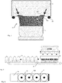
- Fig. 7 shows a detailed representation of a curling process.
- the first holding device 2 is shown, which is delivered to the second holding device 4.
- the first holding device has a circumferential groove 24, which contacts a curl fold 10c when the container is compressed.
- this circumferential stop as mentioned above, tempered.
- the first holding device preferably also has an extension, ie a section in which a cross-section of the holding device widens from the bottom upwards. This (in Fig. 7 not shown) also serves to act on the Einrollfalte 10c.
- position detection means 28 may be provided which detect a position of the curl fold 10c and / or a relative position between the holding devices 2, 4.
- the compressed air which is pressed out of the container during compression, again for biasing the following containers and to recycle it. It is also conceivable that an exhaust air of the presented blow molding machine can be used to pressurize the containers here.
- the advantage could be that, for example, purified air or sterile air from the blow molding machine can also be used for prestressing.
- the generated compressed air can be used for pneumatic drives.
- Fig. 8 shows a further illustration of the device according to the invention, in which case also centering elements 23 are indicated, which center these on delivery to the plastic containers 10. This may be, for example, so-called centering bells, which align a mouth section of the containers.
- Fig. 9 shows correspondingly an arrangement of four second holding means 4 with plastic containers 10 arranged therein.
- the reference numeral 15 denotes a means of transport such as a conveyor belt or a transport carrier.
- Reference numeral 10d refers to a mouth portion of the containers 10.
- the holding devices 2 were delivered to the holding devices 4 and the containers are thus completely compressed. It is advantageous if when compressing no sharp-edged folds with so-called white fracture arise because the container otherwise have uncomfortable wrinkles after decompression and filling and weak points also arise at these wrinkles, and thus the containers no longer have the required pressure stability and thus, for example Carbonated drinks are unusable.
- the containers be biased with a slight pressure, for example by a valve in the stamper which seals on the mouth. Then, the holding device 2 presses the container together and by the volume reduction, the pressure in the container continues to increase.
- the internal pressure in the container may not rise arbitrarily, otherwise the pressure force would increase extremely and the container could eventually burst. Therefore, the air is discharged from the container regulated from a certain pressure to maintain a certain pressure in the container.
- the Applicant has found that the curling operation can be rolled up nicely at a pressure in the range of 2 to 2.9 bar, and preferably about 2.2 bar (gauge) or more.
- an electronic pressure control valve can be used, which opens so far from a predetermined and reached pressure inside the container that the pressure is never higher. This in turn is advantageous because the force required to compress the containers depends directly on the pressure in the container. At an internal pressure of 2.5 bar, the force on the holding devices, or each individual holding device already about 15.3 kN, which corresponds to a weight of about 1.53 t. On the other hand, if the pressure is too low, uncontrolled wrinkles with whitening may form on the container.
- the advantages of the invention are that the compressed containers can be stacked well in this way, besides being cost-effective to transport while retaining their properties.
- the re-rolled containers still have the same barrier properties and the same pressure stability as before curling, as long as there are no sharp-edged wrinkles in the PET material.
- FIGS. 10 to 12 show a further embodiment of the device according to the invention.
- the containers 10 are brought via a transport device 12 to the first holding devices 2.
- these second holding devices are arranged in or relative to the transport direction of the containers stationary below the first transport devices 2.
- the containers are also driven in the intended position for compression and then the second holding means 4 are closed.
- Fig. 11 illustrates this process. It can be seen that the second holding devices 4 are here constructed in two parts and have a part 4a and a part 4b. As soon as the containers 10 are in the correct position, these parts 4a, 4b are delivered to each other in the direction Z, so that the in Fig. 12 shown state results. Subsequently the containers with the in FIGS. 11 and 12 compressed from above first holding means 2 (not shown).
- This embodiment has an advantage that the second holding devices 4 are always positioned correctly relative to the first holding devices 2 in the transport direction X of the containers 10.
- the second holding devices must be formed in two parts and preferably half-shell-like.
- Fig. 13 illustrates the compression of the container and in particular the action on the curl fold 10c.
- This curl fold 10c is in Fig. 14 shown.
- the reference numeral 25 denotes a transition region of the first holding device 2. In this transition region 25, a cross section of the first holding device 2 expands from bottom to top. This is preferably a continuous extension.
- the holding device preferably has a circular cross section (perpendicular to the feed direction) at least in the transition section. It can also be seen that this transition region is curved.
- the reference numeral 24 denotes a heating device, which heats the stop or the transition region 25.
- the reference numeral 26 roughly indicates schematically a pressurizing device, which can promote a detachment of the container from the first holding device by application of compressed air
- the reference numeral 23 denotes a centering, which serves to center the container, and can receive the mouth region of the container or a thread of the container.
- Fig. 14 shows a representation of a rolled-up container.
- a temperature control was used, that is, by means of the heater 24, the transition region 25 was heated. It can be seen that the curl fold 10c is pressed outward here and so the Radius R yields. In this way it is possible to stack the compressed containers into each other and also to separate them again.
- Fig. 15 shows a representation not according to the invention, in which no tempering was used. It can be seen that here the radius r is smaller than that in Fig. 14 shown radius R, or the curl fold 10c further protrudes inward. These curls fold tightly around the next container when stacked and they are less likely to separate again
- FIG. 16 an illustration of a device according to the invention is shown.
- the second holding devices 4 are shown, it being immaterial here whether these are moved along with the transport device or are already below the first holding devices 2. It is also one of the first holding devices 2 shown with their inner life.
- a plunger element 82 which here in vertical
- the reference numeral 84 denotes a drive device, such as a hydraulic and preferably pneumatic drive device, which initiates the movement of this plunger element 82.
- this plunger member 82 can also be used during compression to partially seal the mouth 10a of the container so that only a defined amount of air can escape from the container during compression.
Landscapes
- Engineering & Computer Science (AREA)
- Mechanical Engineering (AREA)
- Manufacturing & Machinery (AREA)
- Auxiliary Devices For And Details Of Packaging Control (AREA)
- Casting Or Compression Moulding Of Plastics Or The Like (AREA)
- Blow-Moulding Or Thermoforming Of Plastics Or The Like (AREA)
- Containers Having Bodies Formed In One Piece (AREA)
Claims (12)
- Appareil (1) destiné à comprimer des contenants en matière plastique (10), comprenant un premier dispositif de support (2), lequel est adapté à porter une première zone (10a) d'un contenant (10) à vider, d'un deuxième dispositif de support (4), lequel est adapté à porter et/ou à soutenir une deuxième zone (10b) du contenant (10) à vider, dans lequel la deuxième zone (10b) est espacée de la première zone (10a) avec un moyen de déplacement (17, 19), lequel est adapté à déplacer le premier dispositif de support (2) en direction du deuxième dispositif de support (4), afin de comprimer le contenant (10) situé entre le premier dispositif de support (2) et le deuxième dispositif de support (4), dans lequel le premier dispositif de support (2) présente une section transversale de préférence plus petite qu'une section transversale du contenant à comprimer, de sorte que le premier dispositif de support présentant la première zone (10a) du contenant portée par le premier dispositif de support (2) peut être introduit dans une autre partie du contenant (10) avec formation d'un point de pliage (10c) périphérique par rapport à une direction longitudinale (Y) du contenant (10),
dans lequel
un élément de butée (22) est situé sur le premier dispositif de support (2) et est en contact avec le point de pliage (10c) dans une position relative prédéfinie du premier dispositif de support (2) par rapport au deuxième dispositif de support (4) et l'appareil (1) comprend un dispositif de génération de pression (26), lequel expose un espace intérieur du contenant à comprimer, au moins temporairement pendant la compression de ce dernier, à une pression intérieure supérieure à la pression extérieure régnant autour du contenant (10), dans lequel un contour extérieur du premier dispositif de support (2) est adapté à un contour du contenant (10) résultant de la compression du contenant (10), afin d'éviter la formation de coudes et de pliures,
caractérisé en ce que
le premier dispositif de support présente un dispositif de thermorégulation (24) destiné à thermo-réguler au moins une partie du premier dispositif de support (2). - Appareil (1) selon la revendication 1,
caractérisé en ce que
l'élément de butée (22) est formé de manière périphérique par rapport à la direction longitudinale du dispositif de support. - Appareil (1) selon au moins l'une des revendications précédentes,
caractérisé en ce que
le premier dispositif de support (2) présente une partie de transition (25) dans laquelle une section transversale du premier dispositif de support s'élargit en continu. - Appareil (1) selon au moins l'une des revendications précédentes,
caractérisé en ce que
l'élément de butée (22) est agencé sur le premier dispositif de support par l'intermédiaire d'une partie de transition (25) et cette partie de transition est une partie (25) courbée. - Appareil (1) selon la revendication 1,
caractérisé en ce que
le dispositif de thermorégulation (24) sert à thermo-réguler au moins une partie de l'élément de butée (22). - Appareil (1) selon au moins l'une des revendications précédentes,
caractérisé en ce que
l'appareil (1) comprend un élément de fermeture, lequel ferme au moins en partie une embouchure du contenant à comprimer afin de permettre une sortie contrôlée d'air du contenant (10) pendant la compression dudit contenant. - Appareil (1) selon la revendication 6,
caractérisé en ce que
un élément soupape ou un élément d'étranglement est agencé dans l'élément de fermeture. - Appareil (1) selon au moins l'une des revendications précédentes,
caractérisé en ce que
l'appareil présente en outre un dispositif d'extraction pour extraire un contenant comprimé du premier dispositif de support. - Appareil (1) selon au moins l'une des revendications précédentes,
caractérisé en ce que
l'appareil (1) présente un support (14) sur lequel plusieurs premiers dispositifs de support (2) sont agencés. - Appareil (1) selon au moins l'une des revendications précédentes,
caractérisé en ce que
l'appareil comprend un dispositif de transport (12), lequel amène les contenants en matière plastique (10) aux premiers dispositifs de support (2). - Procédé permettant de comprimer des contenants (10), comprenant les étapes :- de fourniture de contenants en matière plastique (10) ;- de compression de ces contenants en matière plastique (10), dans lequel un premier dispositif de support (2) porte une première zone (10a) d'un contenant (10) à comprimer, et un deuxième dispositif de support (4) porte une deuxième zone (10b) du contenant (10) à comprimer, dans lequel la deuxième zone (10b) est espacée de la première zone (10a), et un moyen de déplacement (17, 19) déplace le premier dispositif de support (2) en direction du deuxième dispositif de support (4) dans une direction d'avancement (Y), afin de comprimer le contenant (10) situé entre le premier dispositif de support (2) et le deuxième dispositif de support (4), dans lequel le premier dispositif de support présentant la première zone (10a) du contenant portée par le premier dispositif de support (2) est introduit dans une autre partie du contenant (10) avec formation d'un point de pliage (10c) périphérique par rapport à une direction longitudinale du contenant (10),
dans lequel
le point de pliage (10c) est en contact avec un élément de butée (22) situé sur le premier dispositif de support (2) dans une position relative prédéfinie du premier dispositif de support (2) par rapport au deuxième dispositif de support (4) au moins temporairement pendant la compression et un dispositif de génération de pression expose un espace intérieur du contenant à comprimer, au moins temporairement pendant la compression de ce dernier, à une pression intérieure supérieure à la pression extérieure régnant autour du contenant, dans lequel un contour extérieur du premier dispositif de support (2) est adapté à un contour du contenant (10) résultant de la compression du contenant (10), afin d'éviter la formation de coudes et de pliures,
caractérisé en ce que
le premier dispositif de support (2) présente un dispositif de thermorégulation (24) destiné à thermo-réguler au moins une partie du premier dispositif de support (2). - Procédé selon la revendication 11,
caractérisé en ce que
le contenant est précontraint à une pression prédéfinie supérieure à la pression ambiante avant d'être comprimé.
Applications Claiming Priority (2)
| Application Number | Priority Date | Filing Date | Title |
|---|---|---|---|
| DE201310109842 DE102013109842A1 (de) | 2013-09-09 | 2013-09-09 | Vorrichtung und Verfahren zum Komprimieren von Kunststoffbehältnissen unter Verhinderung von Weißbruch |
| PCT/EP2014/069164 WO2015032965A1 (fr) | 2013-09-09 | 2014-09-09 | Dispositif et procédé permettant de comprimer des contenants en matière plastique sans formation d'une rupture blanche |
Publications (2)
| Publication Number | Publication Date |
|---|---|
| EP3043982A1 EP3043982A1 (fr) | 2016-07-20 |
| EP3043982B1 true EP3043982B1 (fr) | 2018-08-01 |
Family
ID=51542342
Family Applications (1)
| Application Number | Title | Priority Date | Filing Date |
|---|---|---|---|
| EP14766423.9A Active EP3043982B1 (fr) | 2013-09-09 | 2014-09-09 | Dispositif et procédé permettant de comprimer des contenants en matière plastique sans formation d'une rupture blanche |
Country Status (6)
| Country | Link |
|---|---|
| US (1) | US20160214342A1 (fr) |
| EP (1) | EP3043982B1 (fr) |
| CN (1) | CN105682901B (fr) |
| DE (1) | DE102013109842A1 (fr) |
| RU (1) | RU2016107980A (fr) |
| WO (1) | WO2015032965A1 (fr) |
Citations (1)
| Publication number | Priority date | Publication date | Assignee | Title |
|---|---|---|---|---|
| WO2003059606A1 (fr) * | 2002-01-16 | 2003-07-24 | Lajos Simon | Dispositif pouvant reduire le volume de bouteilles en matiere plastique |
Family Cites Families (5)
| Publication number | Priority date | Publication date | Assignee | Title |
|---|---|---|---|---|
| US3819789A (en) * | 1969-06-11 | 1974-06-25 | C Parker | Method and apparatus for blow molding axially deformable containers |
| US5206037A (en) * | 1990-08-31 | 1993-04-27 | Robbins Edward S Iii | Apparatus for collapsing a container |
| US5832818A (en) * | 1997-12-17 | 1998-11-10 | Menzak, Jr.; Joseph | Plastic bottle heating element compressor |
| JP2001063717A (ja) * | 1999-08-27 | 2001-03-13 | Yoshino Kogyosho Co Ltd | 合成樹脂製薄肉壜体の取扱い方法 |
| DE102012101507A1 (de) * | 2012-02-24 | 2013-08-29 | Krones Aktiengesellschaft | Zapfanlage mit gesteuerter Flüssigkeitsausgabe |
-
2013
- 2013-09-09 DE DE201310109842 patent/DE102013109842A1/de not_active Withdrawn
-
2014
- 2014-09-09 EP EP14766423.9A patent/EP3043982B1/fr active Active
- 2014-09-09 CN CN201480049577.XA patent/CN105682901B/zh active Active
- 2014-09-09 US US14/917,289 patent/US20160214342A1/en not_active Abandoned
- 2014-09-09 WO PCT/EP2014/069164 patent/WO2015032965A1/fr not_active Ceased
- 2014-09-09 RU RU2016107980A patent/RU2016107980A/ru not_active Application Discontinuation
Patent Citations (1)
| Publication number | Priority date | Publication date | Assignee | Title |
|---|---|---|---|---|
| WO2003059606A1 (fr) * | 2002-01-16 | 2003-07-24 | Lajos Simon | Dispositif pouvant reduire le volume de bouteilles en matiere plastique |
Also Published As
| Publication number | Publication date |
|---|---|
| DE102013109842A1 (de) | 2015-03-12 |
| CN105682901A (zh) | 2016-06-15 |
| WO2015032965A1 (fr) | 2015-03-12 |
| RU2016107980A (ru) | 2017-10-16 |
| CN105682901B (zh) | 2017-09-12 |
| EP3043982A1 (fr) | 2016-07-20 |
| US20160214342A1 (en) | 2016-07-28 |
| RU2016107980A3 (fr) | 2018-03-23 |
Similar Documents
| Publication | Publication Date | Title |
|---|---|---|
| DE3844117C2 (fr) | ||
| DE69210537T2 (de) | Artikel mit Form zur Erfassung der Position sowie Verfahren und Vorrichtung zur deren Herstellung und Verarbeitung | |
| DE1704340C3 (de) | Verfahren und Einrichtung zum Herstellen eines aus thermoplastischem Kunststoff bestehenden Behälters | |
| DE2353209A1 (de) | Tiefgezogener behaelter und verfahren zu seiner herstellung | |
| EP2987616B1 (fr) | Preforme pour la fabrication une bouteille en matiere plastique | |
| DE60201504T2 (de) | Verfahren und vorrichtung zum einhalsen der öffnung eines behälters | |
| EP1163996A2 (fr) | Procédé pour la fabrication d'un récipient fabriqué à partir d'une feuille en matière thermoplastique et un outil pour la mise en oeuvre de cette méthode | |
| EP0175642A2 (fr) | Procédé et installation pour la fabrication d'un objet moulé en matière plastique | |
| DE1291469C2 (de) | Verfahren und Vorrichtung zum Herstellen eines duennwandigen, oben offenen Behaelters aus einer Folie aus thermoplastischem Kunststoff | |
| DE1704313A1 (de) | Verfahren und Vorrichtung zum Formen hohler Erzeugnisse | |
| CH437751A (de) | Verfahren zur Herstellung hohler Gegenstände, Vorrichtung zur Durchführung des Verfahrens und Erzeugnis des Verfahrens | |
| EP3390234B1 (fr) | Moule présentant une coque en plusieurs parties | |
| EP1970190A2 (fr) | Dispositif de traitement de récipients | |
| EP0280204B1 (fr) | Procédé et appareil pour le formage d'un flanc à un corps creux en matière thermoplastique | |
| EP3416806B1 (fr) | Procédé et dispositif pour fabriquer des contenants remplis d'un produit de remplissage liquide et fermés avec un bouchon de fermeture | |
| WO2012130374A1 (fr) | Procédé et dispositif pour la fabrication de récipients | |
| EP1082204B2 (fr) | Procede et dispositif pour produire des corps creux en matiere plastique | |
| DE60310531T2 (de) | Vorrichtung und Verfahren zum Pressformen von Kunststoff-Behältern | |
| EP3043981B1 (fr) | Dispositif et procédé permettant de comprimer des contenants | |
| DE2732978A1 (de) | Verfahren und vorrichtung zur herstellung hohler gegenstaende aus aushaertbaren, plastifizierten stoffen durch blasgiessen | |
| CH618626A5 (fr) | ||
| WO2016030293A1 (fr) | Système de traitement ultérieur de préformes fabriquées par moulage par injection | |
| DE1604712B1 (de) | Vorrichtung zum Herstellen eines tiefgezogenen Behaelteroberteils mit einer von einem Wulstrand umgebenen OEffnung | |
| EP3043982B1 (fr) | Dispositif et procédé permettant de comprimer des contenants en matière plastique sans formation d'une rupture blanche | |
| DE3342434A1 (de) | Verfahren und vorrichtung zum ziehen eines konischen behaelterunterteils aus blech |
Legal Events
| Date | Code | Title | Description |
|---|---|---|---|
| PUAI | Public reference made under article 153(3) epc to a published international application that has entered the european phase |
Free format text: ORIGINAL CODE: 0009012 |
|
| 17P | Request for examination filed |
Effective date: 20160411 |
|
| AK | Designated contracting states |
Kind code of ref document: A1 Designated state(s): AL AT BE BG CH CY CZ DE DK EE ES FI FR GB GR HR HU IE IS IT LI LT LU LV MC MK MT NL NO PL PT RO RS SE SI SK SM TR |
|
| AX | Request for extension of the european patent |
Extension state: BA ME |
|
| DAX | Request for extension of the european patent (deleted) | ||
| 17Q | First examination report despatched |
Effective date: 20170622 |
|
| GRAP | Despatch of communication of intention to grant a patent |
Free format text: ORIGINAL CODE: EPIDOSNIGR1 |
|
| INTG | Intention to grant announced |
Effective date: 20180312 |
|
| GRAS | Grant fee paid |
Free format text: ORIGINAL CODE: EPIDOSNIGR3 |
|
| GRAA | (expected) grant |
Free format text: ORIGINAL CODE: 0009210 |
|
| AK | Designated contracting states |
Kind code of ref document: B1 Designated state(s): AL AT BE BG CH CY CZ DE DK EE ES FI FR GB GR HR HU IE IS IT LI LT LU LV MC MK MT NL NO PL PT RO RS SE SI SK SM TR |
|
| REG | Reference to a national code |
Ref country code: GB Ref legal event code: FG4D Free format text: NOT ENGLISH |
|
| REG | Reference to a national code |
Ref country code: FR Ref legal event code: PLFP Year of fee payment: 5 |
|
| REG | Reference to a national code |
Ref country code: CH Ref legal event code: EP Ref country code: AT Ref legal event code: REF Ref document number: 1023799 Country of ref document: AT Kind code of ref document: T Effective date: 20180815 |
|
| REG | Reference to a national code |
Ref country code: IE Ref legal event code: FG4D Free format text: LANGUAGE OF EP DOCUMENT: GERMAN |
|
| REG | Reference to a national code |
Ref country code: DE Ref legal event code: R096 Ref document number: 502014009059 Country of ref document: DE |
|
| REG | Reference to a national code |
Ref country code: NL Ref legal event code: MP Effective date: 20180801 |
|
| REG | Reference to a national code |
Ref country code: LT Ref legal event code: MG4D |
|
| PG25 | Lapsed in a contracting state [announced via postgrant information from national office to epo] |
Ref country code: NO Free format text: LAPSE BECAUSE OF FAILURE TO SUBMIT A TRANSLATION OF THE DESCRIPTION OR TO PAY THE FEE WITHIN THE PRESCRIBED TIME-LIMIT Effective date: 20181101 Ref country code: GR Free format text: LAPSE BECAUSE OF FAILURE TO SUBMIT A TRANSLATION OF THE DESCRIPTION OR TO PAY THE FEE WITHIN THE PRESCRIBED TIME-LIMIT Effective date: 20181102 Ref country code: BG Free format text: LAPSE BECAUSE OF FAILURE TO SUBMIT A TRANSLATION OF THE DESCRIPTION OR TO PAY THE FEE WITHIN THE PRESCRIBED TIME-LIMIT Effective date: 20181101 Ref country code: SE Free format text: LAPSE BECAUSE OF FAILURE TO SUBMIT A TRANSLATION OF THE DESCRIPTION OR TO PAY THE FEE WITHIN THE PRESCRIBED TIME-LIMIT Effective date: 20180801 Ref country code: LT Free format text: LAPSE BECAUSE OF FAILURE TO SUBMIT A TRANSLATION OF THE DESCRIPTION OR TO PAY THE FEE WITHIN THE PRESCRIBED TIME-LIMIT Effective date: 20180801 Ref country code: PL Free format text: LAPSE BECAUSE OF FAILURE TO SUBMIT A TRANSLATION OF THE DESCRIPTION OR TO PAY THE FEE WITHIN THE PRESCRIBED TIME-LIMIT Effective date: 20180801 Ref country code: NL Free format text: LAPSE BECAUSE OF FAILURE TO SUBMIT A TRANSLATION OF THE DESCRIPTION OR TO PAY THE FEE WITHIN THE PRESCRIBED TIME-LIMIT Effective date: 20180801 Ref country code: RS Free format text: LAPSE BECAUSE OF FAILURE TO SUBMIT A TRANSLATION OF THE DESCRIPTION OR TO PAY THE FEE WITHIN THE PRESCRIBED TIME-LIMIT Effective date: 20180801 Ref country code: IS Free format text: LAPSE BECAUSE OF FAILURE TO SUBMIT A TRANSLATION OF THE DESCRIPTION OR TO PAY THE FEE WITHIN THE PRESCRIBED TIME-LIMIT Effective date: 20181201 Ref country code: FI Free format text: LAPSE BECAUSE OF FAILURE TO SUBMIT A TRANSLATION OF THE DESCRIPTION OR TO PAY THE FEE WITHIN THE PRESCRIBED TIME-LIMIT Effective date: 20180801 |
|
| PG25 | Lapsed in a contracting state [announced via postgrant information from national office to epo] |
Ref country code: HR Free format text: LAPSE BECAUSE OF FAILURE TO SUBMIT A TRANSLATION OF THE DESCRIPTION OR TO PAY THE FEE WITHIN THE PRESCRIBED TIME-LIMIT Effective date: 20180801 Ref country code: LV Free format text: LAPSE BECAUSE OF FAILURE TO SUBMIT A TRANSLATION OF THE DESCRIPTION OR TO PAY THE FEE WITHIN THE PRESCRIBED TIME-LIMIT Effective date: 20180801 Ref country code: AL Free format text: LAPSE BECAUSE OF FAILURE TO SUBMIT A TRANSLATION OF THE DESCRIPTION OR TO PAY THE FEE WITHIN THE PRESCRIBED TIME-LIMIT Effective date: 20180801 |
|
| PG25 | Lapsed in a contracting state [announced via postgrant information from national office to epo] |
Ref country code: EE Free format text: LAPSE BECAUSE OF FAILURE TO SUBMIT A TRANSLATION OF THE DESCRIPTION OR TO PAY THE FEE WITHIN THE PRESCRIBED TIME-LIMIT Effective date: 20180801 Ref country code: MC Free format text: LAPSE BECAUSE OF FAILURE TO SUBMIT A TRANSLATION OF THE DESCRIPTION OR TO PAY THE FEE WITHIN THE PRESCRIBED TIME-LIMIT Effective date: 20180801 Ref country code: RO Free format text: LAPSE BECAUSE OF FAILURE TO SUBMIT A TRANSLATION OF THE DESCRIPTION OR TO PAY THE FEE WITHIN THE PRESCRIBED TIME-LIMIT Effective date: 20180801 Ref country code: CZ Free format text: LAPSE BECAUSE OF FAILURE TO SUBMIT A TRANSLATION OF THE DESCRIPTION OR TO PAY THE FEE WITHIN THE PRESCRIBED TIME-LIMIT Effective date: 20180801 Ref country code: ES Free format text: LAPSE BECAUSE OF FAILURE TO SUBMIT A TRANSLATION OF THE DESCRIPTION OR TO PAY THE FEE WITHIN THE PRESCRIBED TIME-LIMIT Effective date: 20180801 |
|
| REG | Reference to a national code |
Ref country code: CH Ref legal event code: PL |
|
| REG | Reference to a national code |
Ref country code: DE Ref legal event code: R097 Ref document number: 502014009059 Country of ref document: DE |
|
| PG25 | Lapsed in a contracting state [announced via postgrant information from national office to epo] |
Ref country code: SK Free format text: LAPSE BECAUSE OF FAILURE TO SUBMIT A TRANSLATION OF THE DESCRIPTION OR TO PAY THE FEE WITHIN THE PRESCRIBED TIME-LIMIT Effective date: 20180801 Ref country code: DK Free format text: LAPSE BECAUSE OF FAILURE TO SUBMIT A TRANSLATION OF THE DESCRIPTION OR TO PAY THE FEE WITHIN THE PRESCRIBED TIME-LIMIT Effective date: 20180801 Ref country code: SM Free format text: LAPSE BECAUSE OF FAILURE TO SUBMIT A TRANSLATION OF THE DESCRIPTION OR TO PAY THE FEE WITHIN THE PRESCRIBED TIME-LIMIT Effective date: 20180801 |
|
| PLBE | No opposition filed within time limit |
Free format text: ORIGINAL CODE: 0009261 |
|
| STAA | Information on the status of an ep patent application or granted ep patent |
Free format text: STATUS: NO OPPOSITION FILED WITHIN TIME LIMIT |
|
| REG | Reference to a national code |
Ref country code: BE Ref legal event code: MM Effective date: 20180930 |
|
| REG | Reference to a national code |
Ref country code: IE Ref legal event code: MM4A |
|
| PG25 | Lapsed in a contracting state [announced via postgrant information from national office to epo] |
Ref country code: LU Free format text: LAPSE BECAUSE OF NON-PAYMENT OF DUE FEES Effective date: 20180909 |
|
| 26N | No opposition filed |
Effective date: 20190503 |
|
| GBPC | Gb: european patent ceased through non-payment of renewal fee |
Effective date: 20181101 |
|
| PG25 | Lapsed in a contracting state [announced via postgrant information from national office to epo] |
Ref country code: IE Free format text: LAPSE BECAUSE OF NON-PAYMENT OF DUE FEES Effective date: 20180909 |
|
| PG25 | Lapsed in a contracting state [announced via postgrant information from national office to epo] |
Ref country code: BE Free format text: LAPSE BECAUSE OF NON-PAYMENT OF DUE FEES Effective date: 20180930 Ref country code: LI Free format text: LAPSE BECAUSE OF NON-PAYMENT OF DUE FEES Effective date: 20180930 Ref country code: SI Free format text: LAPSE BECAUSE OF FAILURE TO SUBMIT A TRANSLATION OF THE DESCRIPTION OR TO PAY THE FEE WITHIN THE PRESCRIBED TIME-LIMIT Effective date: 20180801 Ref country code: CH Free format text: LAPSE BECAUSE OF NON-PAYMENT OF DUE FEES Effective date: 20180930 |
|
| PG25 | Lapsed in a contracting state [announced via postgrant information from national office to epo] |
Ref country code: GB Free format text: LAPSE BECAUSE OF NON-PAYMENT OF DUE FEES Effective date: 20181101 |
|
| PG25 | Lapsed in a contracting state [announced via postgrant information from national office to epo] |
Ref country code: MT Free format text: LAPSE BECAUSE OF FAILURE TO SUBMIT A TRANSLATION OF THE DESCRIPTION OR TO PAY THE FEE WITHIN THE PRESCRIBED TIME-LIMIT Effective date: 20180801 |
|
| PG25 | Lapsed in a contracting state [announced via postgrant information from national office to epo] |
Ref country code: TR Free format text: LAPSE BECAUSE OF FAILURE TO SUBMIT A TRANSLATION OF THE DESCRIPTION OR TO PAY THE FEE WITHIN THE PRESCRIBED TIME-LIMIT Effective date: 20180801 |
|
| PG25 | Lapsed in a contracting state [announced via postgrant information from national office to epo] |
Ref country code: PT Free format text: LAPSE BECAUSE OF FAILURE TO SUBMIT A TRANSLATION OF THE DESCRIPTION OR TO PAY THE FEE WITHIN THE PRESCRIBED TIME-LIMIT Effective date: 20180801 |
|
| PG25 | Lapsed in a contracting state [announced via postgrant information from national office to epo] |
Ref country code: HU Free format text: LAPSE BECAUSE OF FAILURE TO SUBMIT A TRANSLATION OF THE DESCRIPTION OR TO PAY THE FEE WITHIN THE PRESCRIBED TIME-LIMIT; INVALID AB INITIO Effective date: 20140909 Ref country code: CY Free format text: LAPSE BECAUSE OF FAILURE TO SUBMIT A TRANSLATION OF THE DESCRIPTION OR TO PAY THE FEE WITHIN THE PRESCRIBED TIME-LIMIT Effective date: 20180801 Ref country code: MK Free format text: LAPSE BECAUSE OF NON-PAYMENT OF DUE FEES Effective date: 20180801 |
|
| REG | Reference to a national code |
Ref country code: AT Ref legal event code: MM01 Ref document number: 1023799 Country of ref document: AT Kind code of ref document: T Effective date: 20190909 |
|
| PG25 | Lapsed in a contracting state [announced via postgrant information from national office to epo] |
Ref country code: AT Free format text: LAPSE BECAUSE OF NON-PAYMENT OF DUE FEES Effective date: 20190909 |
|
| P01 | Opt-out of the competence of the unified patent court (upc) registered |
Effective date: 20230523 |
|
| PGFP | Annual fee paid to national office [announced via postgrant information from national office to epo] |
Ref country code: DE Payment date: 20250730 Year of fee payment: 12 |
|
| PGFP | Annual fee paid to national office [announced via postgrant information from national office to epo] |
Ref country code: IT Payment date: 20250825 Year of fee payment: 12 |
|
| PGFP | Annual fee paid to national office [announced via postgrant information from national office to epo] |
Ref country code: FR Payment date: 20250808 Year of fee payment: 12 |