EP3044047B1 - Variantes de structure pour essuie-glace à épine de nageoire - Google Patents
Variantes de structure pour essuie-glace à épine de nageoire Download PDFInfo
- Publication number
- EP3044047B1 EP3044047B1 EP14747396.1A EP14747396A EP3044047B1 EP 3044047 B1 EP3044047 B1 EP 3044047B1 EP 14747396 A EP14747396 A EP 14747396A EP 3044047 B1 EP3044047 B1 EP 3044047B1
- Authority
- EP
- European Patent Office
- Prior art keywords
- wiper blade
- connecting elements
- wiper device
- along
- windshield
- Prior art date
- Legal status (The legal status is an assumption and is not a legal conclusion. Google has not performed a legal analysis and makes no representation as to the accuracy of the status listed.)
- Active
Links
Images




Classifications
-
- B—PERFORMING OPERATIONS; TRANSPORTING
- B60—VEHICLES IN GENERAL
- B60S—SERVICING, CLEANING, REPAIRING, SUPPORTING, LIFTING, OR MANOEUVRING OF VEHICLES, NOT OTHERWISE PROVIDED FOR
- B60S1/00—Cleaning of vehicles
- B60S1/02—Cleaning windscreens, windows or optical devices
- B60S1/04—Wipers or the like, e.g. scrapers
- B60S1/32—Wipers or the like, e.g. scrapers characterised by constructional features of wiper blade arms or blades
- B60S1/38—Wiper blades
- B60S1/3801—Wiper blades characterised by a blade support harness consisting of several articulated elements
-
- B—PERFORMING OPERATIONS; TRANSPORTING
- B60—VEHICLES IN GENERAL
- B60S—SERVICING, CLEANING, REPAIRING, SUPPORTING, LIFTING, OR MANOEUVRING OF VEHICLES, NOT OTHERWISE PROVIDED FOR
- B60S1/00—Cleaning of vehicles
- B60S1/02—Cleaning windscreens, windows or optical devices
- B60S1/04—Wipers or the like, e.g. scrapers
- B60S1/32—Wipers or the like, e.g. scrapers characterised by constructional features of wiper blade arms or blades
- B60S1/34—Wiper arms; Mountings therefor
- B60S1/3411—Wiper arms; Mountings therefor with means for varying wiper-blade pressure on windshield during operation
Definitions
- the invention relates to a windshield wiper device for a vehicle, in particular a motor vehicle.
- Windshield wiper devices typically have a wiper arm or wiper lever, with a wiper blade being moved on the windshield of a motor vehicle (see e.g. document JPH0542020U ).
- the wiper blade is moved between a first turning position and a second turning position.
- the wiper arm is connected to a wiper motor via the drive shaft.
- the wiper blade easily loses contact with the windshield, particularly on windshields with large changes in curvature. This can lead to unwiped wiping areas or fog formation, particularly in the case of strongly curved windows.
- boundary conditions that should also be taken into account. These include the outlay in production or the production costs, the material costs, but also the properties of the windshield wiper device, in particular its function under a wide range of conditions and its durability under a large number of conditions.
- wiping devices for vehicles it is important to consider that the cost pressure is increasing steadily and that the vehicles can be used in a large number of climatic conditions, so that, for example, extreme temperature values occur permanently and / or with large fluctuations.
- a windshield wiper device based on the fin jet principle for a vehicle, in particular a motor vehicle.
- the windshield wiper device comprises a wiper blade with an elongated upper part and an elongated lower part, which are designed to be at least partially bendable.
- several connecting elements are provided for connecting the upper part and the lower part, the connecting elements being spaced apart from one another along a longitudinal extension of the wiper blade.
- the connecting elements are designed to enable a movement of the upper part and the lower part relative to one another with a movement component along a longitudinal extension of the wiper blade.
- the connecting elements are arranged relative to the lower part in such a way that, in an unloaded state of the wiper blade, an angle ⁇ n of the respective longitudinal axes of the connecting elements relative to the lower part changes at least partially along a longitudinal extension of the wiper blade, in particular changes monotonically, and in particular changes strictly monotonically.
- a windshield wiper device for a vehicle, in particular a motor vehicle
- the windshield wiper device comprises a wiper blade with an elongated upper part and an elongated lower part, which are at least partially designed to be bendable.
- several connecting elements are provided for connecting the upper part and the lower part, the connecting elements being spaced apart from one another along a longitudinal extension of the wiper blade.
- the connecting elements are designed to enable a movement of the upper part and the lower part relative to one another with a movement component along a longitudinal extension of the wiper blade.
- the upper part of the wiper blade has a varying thickness along a longitudinal extension of the wiper blade. In particular, the thickness of the upper part decreases along the longitudinal extension of the wiper blade towards one end of the wiper blade.
- a windshield wiper device based on the fin jet principle for a vehicle, in particular a motor vehicle.
- the windshield wiper device comprises a wiper blade with an elongated upper part and an elongated lower part, which are designed to be at least partially bendable.
- several connecting elements are provided for connecting the upper part and the lower part, the connecting elements being spaced apart from one another along a longitudinal extension of the wiper blade.
- the connecting elements are designed to enable a movement of the upper part and the lower part relative to one another with a movement component along a longitudinal extension of the wiper blade.
- the lower part of the wiper blade has a varying thickness along a longitudinal extension of the wiper blade.
- a windshield wiper device for a vehicle, in particular a motor vehicle
- the windshield wiper device comprises a wiper blade with an elongated upper part and an elongated lower part, which are designed to be at least partially bendable.
- several connecting elements are provided for connecting the upper part and the lower part, the connecting elements along one The longitudinal extension of the wiper blade are spaced apart from one another.
- the connecting elements are designed to enable a movement of the upper part and the lower part relative to one another with a movement component along a longitudinal extension of the wiper blade.
- the wiper blade is configured in such a way that the wiper blade has at least one change in curvature along the longitudinal extension of the wiper blade, in particular a change in sign in the curvature.
- windshield wiper devices for vehicles can be produced in a particularly favorable manner and for a plurality of different areas of application.
- the present embodiments of the windshield wiper device in which the connecting elements are arranged relative to the lower part in such a way that in an unloaded state of the wiper blade, an angle ⁇ n of the respective longitudinal axes of the connecting elements relative to the lower part changes at least partially along a longitudinal extension of the wiper blade, enable a particularly good one Adaptation to the curvature of a disc. This ensures particularly good and exact wiping of the window. Areas of the pane that have not been wiped and the formation of fog on the pane can largely be avoided.
- the structural design of the windshield wiper device described above enables a largely uniform contact pressure of the windshield wiper device on the windshield, so that a high wiping quality is provided.
- an angle ⁇ n of the respective longitudinal axes of the connecting elements relative to the lower part can continuously change, ie increase or decrease, at least partially along a longitudinal extension of the wiper blade. Since the angles of the connecting elements are discrete values, “continuous” in this context and in other contexts in the context of this disclosure is not strictly mathematical to be defined but in the sense of "constantly”, “constantly”, and / or "without interruption”.
- the wiper blade has at least one first region in which the angle ⁇ n of the longitudinal axes of the connecting elements relative to the lower part decreases, in particular monotonously, in particular, along a longitudinal extension of the wiper blade towards a wiper blade end strictly monotonically decreases.
- the windshield wiper device can have at least a second region in which the angle ⁇ n of the longitudinal axes of the connecting elements increases relative to the lower part along a longitudinal extent of the wiper blade towards a wiper blade end, in particular increases monotonically, in particular strictly monotonically.
- the first area with decreasing angles is closer to the end of the windshield wiper device or closer to the outer connection position of the upper part and the lower part, while the second area is closer to the connection piece or a holder or a fastening part of the windshield wiper device.
- the connecting elements are configured such that the distance between the upper part and the lower part changes at least partially along a longitudinal extension of the wiper blade, in particular changes continuously along a longitudinal extension of the wiper blade.
- the distance between the upper part and the lower part can decrease along the longitudinal extent of the wiper blade in a first area of the wiper blade and increase in a second area of the wiper blade.
- the wiper blade can comprise an area in which the distance between the upper part and the lower part is essentially constant along the longitudinal extension of the wiper blade.
- the connecting elements are configured such that the changing distance between the upper part and the Lower part passes through a minimum distance along a longitudinal extension of the wiper blade towards a wiper blade end.
- the minimum distance between the upper part and the lower part can be arranged between a connection piece and a connection position of the upper part and the lower part along a longitudinal extension of the wiper blade.
- the minimum distance between the upper part and the lower part can be arranged approximately centrally along a longitudinal extent of the wiper blade.
- the minimum distance between the upper part and the lower part can also be arranged in a region of the wiper blade which is shifted towards the end of the wiper blade.
- the connecting elements are articulated to the lower part and / or the upper part.
- the connecting elements are connected to the lower part and / or the upper part by means of a first film hinge.
- the first film hinge can be formed in one piece with the connecting element and the upper part and / or the lower part.
- the one-piece design of the film hinge allows simple and inexpensive manufacture. In this way, the wiper blades or the windshield wiper devices can be made available without tools if they are designed accordingly.
- the use of film hinges in particular the one-piece design of the film hinges with the connecting elements and the upper part and / or the lower part, enables production by injection molding.
- the width of the lower part and / or the width of the upper part decreases, in particular steadily, along the longitudinal extension of the wiper blade towards a wiper blade end.
- a windshield wiper device which has a moment of inertia which decreases towards the end of the wiper blade.
- a largely uniform contact pressure of the windshield wiper device on the windshield and a homogeneous force distribution of the windshield wiper device can be provided, so that an improved adaptation to the windshield and a high wiping quality are provided.
- the thickness of the upper part decreases, in particular monotonically, along the longitudinal extension of the wiper blade towards a wiper blade end. According to embodiments, the thickness of the upper part decreases monotonically, in particular strictly monotonically, along the longitudinal extent of the wiper blade towards a wiper blade end. As a result, a windshield wiper device can be provided which has a moment of inertia that decreases towards the end of the wiper blade.
- a windshield wiper device is provided with which a largely uniform contact pressure of the windshield wiper device on the window and a homogeneous force distribution of the windshield wiper device is possible, so that an improved adaptation to the window and a high wiping quality can be ensured.
- the thickness of the lower part varies along the longitudinal extent of the wiper blade.
- the lower part has a plurality of regions with a smaller thickness and a plurality of regions with a greater thickness.
- the areas with the smaller thickness and the areas with the greater thickness are arranged alternately along the longitudinal extent of the wiper blade.
- the areas of lesser thickness are formed by film hinges that are connected to the areas of greater thickness, in particular are connected in one piece. This provides a windshield wiper device with improved adaptability to a windshield, whereby a high wiping quality can be ensured.
- the lower part comprises a plurality of lower part segments which are connected to one another in an articulated manner.
- the lower part segments are connected to one another by means of a second film hinge.
- the second film hinge is designed in one piece with the lower part segments. This provides a windshield wiper device with improved adaptability to a windshield, whereby a high wiping quality can be ensured.
- the one-piece design of the second film hinge allows simple and inexpensive manufacture. In this way, the wiper blades or the windshield wiper devices can be made available without tools if they are designed accordingly.
- a plurality of the connecting elements are connected to the areas of greater thickness of the lower part, in particular connected approximately centrally to the areas of greater thickness of the lower part.
- the areas of greater thickness of the lower part are formed by lower part segments.
- a plurality of the connecting elements are connected to the lower part segments, in particular connected approximately centrally to the lower part segments.
- the windshield wiper device is made of at least one material from the group consisting of: POM, PA, TPE, in particular TPE-S, TPE-O, TPE-U, TPE-A TPE- V and TPE-E.
- the choice of material for the windshield wiper device allows a selection of the material properties and thus an adjustment of the physical, in particular mechanical, properties of the windshield wiper device.
- the choice of materials from the group consisting of: POM, PA, TPE, in particular TPE-S, TPE-O, TPE-U, TPE-A, TPE-V and TPE-E enables production in the injection molding process, in particular in a 2-component process Spraying process. This makes it possible to provide windshield wiper devices that can be manufactured easily and inexpensively.
- FIGs 1 and 2 show schematic representations of a wiper blade 2 of a windshield wiper device for a vehicle, in particular for a motor vehicle, in a basic position ( Figure 1 ), ie in an unloaded state, and in a position applied to a disc 4 ( Figure 2 ) according to the embodiments described herein.
- the wiper blade comprises an elongated upper part 10 and an elongated lower part 12, which are designed to be at least partially flexible.
- several connecting elements 18 are provided for connecting the upper part 10 and the lower part 12, the connecting elements 18 being spaced from one another along a longitudinal extension 8 of the wiper blade 2.
- the connecting elements 18 are designed to enable a movement of the upper part 10 and the lower part 12 relative to one another with a movement component along a longitudinal extension 8 of the wiper blade 2. Furthermore, the connecting elements 18 are arranged relative to the lower part 12 such that in an unloaded state of the wiper blade 2 an angle ⁇ n of the respective longitudinal axes 24 of the connecting elements 18 relative to the lower part 12 changes at least partially along a longitudinal extension 8 of the wiper blade 2, in particular constantly changed or changed monotonically or strictly monotonously.
- the wiper blade shown in the unloaded state are the angles ⁇ n of the respective longitudinal axes of the connecting elements 18 relative to the lower part 12, which change along the longitudinal extension 8 of the wiper blade 2, with ⁇ 1 , ⁇ 2 , ⁇ 3 , ... ⁇ n-1 , ⁇ n denotes.
- a loaded state of the wiper blade ie in a Position applied to the disc, as exemplified in Fig. 2 is shown, the angles ⁇ n of the respective longitudinal axes 24 of the connecting elements 18 change relative to the lower part 12 compared to the unloaded state.
- the wiper blade has at least one first area in which the angle ⁇ n of the longitudinal axes 24 of the connecting elements 18 relative to the lower part 12 decreases along a longitudinal extension 8 of the wiper blade 2 towards a wiper blade end , in particular monotonously, in particular strictly monotonously, decreases.
- the wiper blade 2 can have at least a second region in which the angle ⁇ n of the longitudinal axes 24 of the connecting elements 18 relative to the lower part 12 increases along a longitudinal extension 8 of the wiper blade 2 towards a wiper blade end, in particular increases monotonically, in particular strictly monotonously.
- the second area of the wiper blade in which the angle ⁇ n of the longitudinal axes 24 of the connecting elements 18 relative to the lower part 12 along the longitudinal extension 8 of the wiper blade 2 increases towards a wiper blade end is arranged at an inner position of the wiper blade, which is in the vicinity a fastening device of the wiper blade, for example a fastening device for a wiper arm.
- a windshield wiper device can be made available which enables particularly good adaptation to the curvature of a windshield.
- a largely uniform contact pressure of the windshield wiper device on the windshield and a homogeneous force distribution of the windshield wiper device can be provided, so that a high wiping quality is provided.
- the connecting elements 18, in particular when the wiper blade 2 is in an unloaded state are attached to the lower part 12 such that the longitudinal axes 24 of the connecting elements 18 extend at angles ⁇ n to the lower part 12 lie between a lower angle limit value ⁇ nu and an upper limit value ⁇ no .
- ⁇ nu 10 °
- ⁇ nu 15 °
- ⁇ nu 20 °
- the upper angle limit value ⁇ no 80 °
- a particularly stable windshield wiper device can be provided with which a largely uniform contact pressure can be generated on the windshield, so that an improved adaptation of the wiper blade to the windshield and a high wiping quality is provided.
- the connecting elements 18 are configured such that the distance between the upper part 10 and the lower part 12 changes at least partially along a longitudinal extension 8 of the wiper blade 2, in particular continuously in a first area reduced and steadily enlarged in a second area.
- the distance h between the upper part 10 and the lower part 12 along the longitudinal extension 8 of the wiper blade 2 can also include a region in which the distance h between the upper part 10 and the lower part 12 along the longitudinal extension 8 of the wiper blade 2 is essentially constant.
- the distance h between the upper part 10 and the lower part 12 can decrease along the longitudinal extension 8 of the wiper blade 2 from an inner distance value h J to an outer distance value h A , in particular monotonically, in particular strictly monotonically.
- the distance h between the upper part 10 and the lower part 12 along the longitudinal extension 8 of the wiper blade 2 in a first region of the wiper blade 2 can decrease from an inner distance value h J to an average distance value h M , in particular decrease continuously or monotonically, and increase in a second region of the wiper blade 2 from the mean distance value h M to the outer distance value h A , in particular increase monotonically, in particular strictly monotonically.
- the mean distance value h M does not necessarily have to be arranged in the middle of the longitudinal extent of the wiper blade.
- the mean distance value h M can be shifted towards an outer position or an inner position of the wiper blade.
- an outer position of the wiper blade is to be understood as the end of the wiper blade which is located at an end of the wiper blade remote from the fastening device.
- an “inner position” is to be understood as a position of the wiper blade which is in the vicinity of a fastening device of the wiper blade, for example a fastening device for a wiper arm.
- the connecting elements 18 are configured such that the distance between the upper part 10 and the lower part 12, which changes towards a wiper blade end, along a longitudinal extension 8 of the wiper blade 2 is a distance minimum, for example a distance minimum with the mean distance value h M.
- the distance between the upper part 10 and the lower part 12 along the longitudinal extent 8 of the wiper blade is primarily determined by the lengths of the connecting elements 18 and their angles ⁇ n of the longitudinal axes 24 relative to the lower part 12.
- the inner distance value h J is at least 15 mm, in particular at least 25 mm, in particular at least 35 mm.
- the outer distance value h A is at least 10 mm, in particular at least 12.5 mm, in particular at least 15 mm.
- the mean distance value h M is at least 7.5 mm, in particular at least 7.5 mm, in particular at least 12.5 mm.
- the connecting elements 18 are articulated to the lower part 12 and / or the upper part 10.
- the connecting elements 18 are connected to the lower part 12 and / or the upper part 10 by means of a first film hinge 20.
- the first film hinge 20 can be formed in one piece with the connecting element 18 and the upper part 10 and / or the lower part 12.
- the one-piece design of the film hinge allows simple and inexpensive manufacture. So they can Wiper blades or the windshield wiper devices can be made available without tools if they are designed accordingly.
- the use of film hinges in particular the one-piece design of the film hinges with the connecting elements and the upper part and / or the lower part, enables production by injection molding.
- a windshield wiper device for a vehicle, in particular a motor vehicle
- the windshield wiper device comprises a wiper blade with an elongated upper part and an elongated lower part, which are designed to be at least partially bendable.
- several connecting elements are provided for connecting the upper part and the lower part, the connecting elements being spaced apart from one another along a longitudinal extension of the wiper blade.
- the connecting elements are designed to enable a movement of the upper part and the lower part relative to one another with a movement component along a longitudinal extension of the wiper blade.
- the upper part of the wiper blade has a varying thickness along a longitudinal extension of the wiper blade. In particular, the thickness of the upper part decreases along the longitudinal extension of the wiper blade towards one end of the wiper blade.
- the thickness of the upper part decreases along the longitudinal extent of the wiper blade, in particular monotonically, in particular strictly monotonously.
- a windshield wiper device is thus provided which has a moment of inertia decreasing towards the end of the wiper blade, in particular a moment of inertia which decreases, in particular monotonically, in particular strictly monotonically, decreasing towards the end of the wiper blade.
- the lower part of the wiper blade has a varying thickness along a longitudinal extension of the wiper blade.
- the thickness of the lower part decreases along the longitudinal extension of the wiper blade towards one end of the wiper blade.
- the thickness of the lower part decreases along the longitudinal extent of the wiper blade, in particular monotonically, in particular strictly monotonously.
- the end of the wiper blade is to be understood as an outer position of the wiper blade which is located at an end of the wiper blade remote from the fastening device.
- an “inner position” is to be understood as a position of the wiper blade which is in the vicinity of a fastening device of the wiper blade, for example a fastening device for a wiper arm.
- the elongated upper part 10 and / or the elongated lower part 12 can have an outer thickness D E at an outer position at which the ends of the upper part and the lower part can be connected and at an inner position at which the wiper blade is rotatably mounted may have an inner thickness D M.
- the outer thickness D E of the upper part and / or the lower part is at least 1.5 mm, in particular at least 2.0 mm, in particular at least 3.0 mm.
- Embodiments of the wiper blade, which can be combined with other embodiments described herein, is the inner thickness D M of the upper part and / or the lower part, at least 2.0 mm, in particular at least 2.5 mm, in particular at least 3.0 mm.
- the wiper blade is configured in such a way that a width of the lower part and / or a width of the upper part decreases, in particular monotonically, in particular strictly monotonically, along the longitudinal extent of the wiper blade towards a wiper blade end.
- a windshield wiper device is thus provided which has a moment of inertia decreasing towards the end of the wiper blade, in particular a moment of inertia which decreases, in particular monotonically, in particular strictly monotonically, decreasing towards the end of the wiper blade. This allows a windshield wiper device are made available, which enables a particularly good adaptation to the curvature of a disk.
- the wiper blade 2 as exemplified in FIG Fig. 4 is shown, an outer width W E at an outer position at which the ends of the elongated upper part 10 and the lower part 12 can be connected to one another, and an inner width W at an inner position at which the wiper blade 2 can be rotatably mounted M have.
- the width of the wiper blade corresponds to the width of the upper part and / or the lower part.
- the width of the upper part and the width of the lower part can differ.
- the width of the lower part can be greater than the width of the upper part or vice versa.
- the outer width W E of the wiper blade, in particular of the upper part and / or the lower part is at least 15 mm, in particular at least 20 mm, in particular at least 25 mm.
- the inner width W M of the wiper blade, in particular of the upper part and / or the lower part is at least 20 mm, in particular at least 25 mm, in particular at least 30 mm.
- a windshield wiper device which has a moment of inertia that decreases, in particular monotonically, in particular strictly monotonically decreasing towards the end of the wiper blade. Furthermore, a largely uniform contact pressure of the windshield wiper device on the windshield as well as a homogeneous force distribution of the windshield wiper device can be provided, so that an improved adaptation to the windshield and a high wiping quality are provided.
- a windshield wiper device for a vehicle, in particular a motor vehicle
- the windshield wiper device comprises a wiper blade with an elongated upper part and an elongated lower part, which are designed to be at least partially bendable.
- several connecting elements are provided for connecting the upper part and the lower part, the connecting elements along one The longitudinal extension of the wiper blade are spaced apart from one another.
- the connecting elements are designed to enable a movement of the upper part and the lower part relative to one another with a movement component along a longitudinal extension of the wiper blade.
- the lower part of the wiper blade has a varying thickness along a longitudinal extension of the wiper blade.
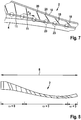
- the lower part has a plurality of regions with a smaller thickness and a plurality of regions with a greater thickness, as is exemplified in FIG Figure 7 is shown.
- the areas with a smaller thickness and the areas with a greater thickness are arranged alternately along the longitudinal extension 8 of the wiper blade 2.
- the regions of lesser thickness are formed by film hinges, in particular second film hinge 23, which are connected to the regions of greater thickness.
- the film hinges which connect the areas of greater thickness can be made in one piece with the areas of greater thickness.
- the lower part 12 comprises a plurality of lower part segments 11 which are articulated to one another, as is exemplified in FIG Fig. 5 is shown.
- the lower part segments 11 can be connected to one another by means of a second film hinge 23, which is in particular made in one piece with the lower part segments 11.
- a plurality of the connecting elements 18 are connected to the lower sub-regions with a greater thickness, as is exemplified in FIGS Figures 5 to 7 is shown, in particular connected somewhat centrally with the lower sub-regions with a greater thickness.
- the connecting elements 18 are configured to apply a force F z in the direction of the longitudinal axes 24 of the connecting elements 18 to be transmitted.
- the connecting elements 18 are designed to be rigid.
- the lower part 12 comprises lower part segments 11
- a plurality of the connecting elements 18 are connected to the lower part segments 11, in particular connected somewhat centrally to the lower part segments 11.
- the lower part segments 11 are configured to transmit a force F R along the longitudinal extension 8 of the wiper blade 2, in particular in the direction of the longitudinal axes 25 of the lower part segments 11.
- the lower part segments 11 are designed to be rigid.
- a windshield wiper device for a vehicle, in particular a motor vehicle
- the windshield wiper device comprises a wiper blade with an elongated upper part and an elongated lower part, which are designed to be at least partially bendable.
- several connecting elements are provided for connecting the upper part and the lower part, the connecting elements being spaced apart from one another along a longitudinal extension of the wiper blade.
- the connecting elements are designed to enable a movement of the upper part and the lower part relative to one another with a movement component along a longitudinal extension of the wiper blade.
- the wiper blade is configured in such a way that the wiper blade has at least one change in curvature along the longitudinal extension of the wiper blade, in particular a change in sign in the curvature.
- the wiper blade comprises a first region with a first curvature ⁇ ⁇ 0 and a second region with a second curvature ⁇ > 0. Furthermore, according to embodiments, the wiper blade can have a third region with a third curvature ⁇ ⁇ 0, the second region of the wiper blade with the second curvature ⁇ > 0 between the first region with the first curvature ⁇ ⁇ 0 and the third region with the third curvature ⁇ ⁇ 0 is arranged, as exemplified in Fig. 8 is shown.
- a windshield wiper device can be made available with which a largely uniform contact pressure can be achieved on the windshield.
- a windshield wiper device can be provided which has an improved adaptation to the windshield and a high wiping quality.
- FIGS 9A and 9B show schematic representations of a wiper blade 2 in a basic position ( Figure 9A ) and in a position applied to a disc ( Figure 9B ) according to embodiments of the windshield wiper device of the disclosure.
- the wiper blade 2 serves to wipe a window 4 of a vehicle, which is for example a motor vehicle, in particular a car.
- the wiper blade 2 is usually attached to a windshield wiper arm which is driven by a motor for wiping.
- the wiper blade 2 has a holder 6 to which it can be attached to the windshield wiper arm.
- the wiper blade 2 is located in the Figure 9A in a basic position, ie in an unloaded state in which the wiper blade 2 is at least partially lifted off the window 4.
- the wiper blade 2 has a longitudinal extension 8 and has an elongated upper part 10 and a likewise elongated lower part 12.
- the longitudinal extensions of the upper part 10 and of the lower part 12 essentially correspond to the longitudinal extension 8 of the wiper blade 2.
- Both the upper part 10 and the lower part 12 are bendable bars or can be designed as bendable bars that are in the Figures 9A and 9B are each exemplified in one piece. This enables a particularly stable construction. It is also possible to design only a part of the upper part 10 and / or the lower part 12 to be flexible. Furthermore, it is alternatively possible for the upper part 10 to be designed in two parts, one end of the two parts of the two-part upper part 10 then being fastened to the holder 6.
- the upper part 10 and / or the Lower part 12 uses a material which has a modulus of elasticity which is in a range between 0.005 kN / mm 2 and 0.5 kN / mm 2 , in particular 0.01 kN / mm 2 and 0.1 kN / mm 2 .
- This enables a suitable flexibility of the upper part 10 and the lower part 12. Together with a suitably configured cross-sectional area of the upper part 10 and the lower part 12, this results in an optimal flexural rigidity.
- the upper part 10 and the lower part 12 are arranged so that they are opposite one another. Both ends of the upper part 10 are firmly connected to one end of the lower part 12 each at outer connection positions 14 and 16. Otherwise, the upper part 10 and the lower part 12 are spaced from one another.
- the upper part 10 and the lower part 12 are connected to one another by connecting elements 18.
- the connecting elements 18 are attached to mutually facing inner longitudinal sides of the upper part 10 and the lower part 12 by means of swivel joints 20.
- the pivots 20 are hinges.
- the swivel joints 20 can be designed as film hinges. This is particularly advantageous when the upper part 10, the lower part 12 and / or the connecting elements 18 are made of a plastic material or are coated with a suitable plastic material.
- a swivel joint is selected from the following group, which consists of: a hinge, a film hinge, a tapering of the material to produce less rigidity along a torsion axis, a joint with an axis of rotation, a means for connecting the upper part to the connecting element or for connecting the lower part to the connecting element, which allows the lower part to be displaced in relation to the upper part along the longitudinal extension, etc.
- Embodiments in which the joints are provided by film hinges thus provide a very simple way of making the joints available for a fin-ray wiper.
- the wiper blade 2 can be provided in one piece, in particular off-tool.
- the film hinges have a high degree of extensibility. This can be made available, for example, by a material selected from the group consisting of PP, PE, POM, and PA.
- the film hinges be made of one or more materials from a group consisting of: TPE (thermoplastic elastomer), for example TPE-S, TPE-O, TPE-U, TPE-A, TPE-V and TPE-E.
- the connecting elements 18 are spaced apart from one another along the longitudinal extent of the wiper blade 2.
- the distances between two adjacent connecting elements 18 are the same. But they can also be chosen differently.
- the distances are advantageously less than 50 mm, in particular less than 30 mm.
- a particularly high flexibility of the windshield wiper device, in particular its lower part, and good adaptation to the curvature and changes in curvature of the window to be wiped can be guaranteed.
- a distance 22 is shown as a representative of the distances between two connecting elements 18.
- Figure 9B shows a schematic representation of the wiper blade 2 according to FIG Figure 9A in a position applied to the disk 4. Since the windshield 4 has a curvature, when the wiper blade 2 is placed against the windshield 4, contact pressure forces act on the lower part 12.Since the upper part 10 and the lower part 12 are flexible bars and the connecting elements 12 are rotatably mounted on the upper part 10 and lower part 12, they are Upper part 10 and the lower part 12 can be displaced relative to one another. As a result of the compressive forces acting on the lower part 12 from below, the wiper blade 2 bends in the direction from which the compressive forces come and lies precisely against the curvature of the window 4.
- the lower part bends in the direction from which the force acts. This is given by the connection of the upper part 10 and the lower part at a connection position 14 and / or 16, the shape, and by swivel joints at the connection between the connecting elements and the upper or lower part.
- a windshield wiper device uses the effect of the tail fins of certain fish, which do not move in the direction of pressure when there is lateral pressure, but rather arch in the opposite direction, i.e. H. in the direction from which the pressure is coming.
- This principle is also referred to as the fin ray principle or "fin ray” principle.
- a windshield wiper device according to the embodiments described herein has the advantage of improved adaptation to a windshield of a motor vehicle.
- the upper part is usually rigid; H. it is not designed to be flexible.
- Figures 9A and 9B show a wiper blade 2 with a longitudinal extension 8 which extends essentially between the connection positions 14 and 16. Such an arrangement is often used for windshield wipers. Alternatively, however, a windshield wiper device can also have only one connection position, which is analogous to FIG Figures 9A and 9B a halving of the windshield wiper device corresponds, and wherein, for example, a rotation axis is provided at a position of the holder 6. Such an arrangement is often used for rear wipers. This is exemplified in the Figures 10A and 10B shown. Optional configurations and details, as described in the individual embodiments, can generally be used for both variants of an arrangement, a windshield wiper device.
- FIG 10A shows a schematic representation of a further exemplary embodiment of the windshield wiper device according to the invention in the basic position.
- the windshield wiper device here is a wiper arm with an integrated wiper blade 2 which is attached to a fastening part 30.
- the fastening part 30 is connected to a wiper motor 32 which drives the fastening part 30 to wipe the window 4.
- the wiper blade 2 is designed in a wedge shape, one end of the upper part 10 being firmly connected to one end of the lower part 12 at an outer connection position 34. The other end of the upper part 10 and the lower part 12 are fastened to the fastening part 30.
- the windshield wiper device corresponds to Figure 10A in principle after that Figure 10A .
- Figure 10B shows a schematic representation of the wiper blade 2 with an integrated wiper arm 30 according to FIG Figure 10B in a position applied to the disk 4.
- compressive forces act from below from the direction of the window 4 on the lower part 12 of the wiper blade 2, so that the lower part 12 and the upper part 10 bend in the direction of the window 4.
- the wiper blade is shown in its position not in contact with the window in such a way that the lower part 12 is essentially straight.
- the lower part is convex in the unloaded state, ie with a curvature that protrudes away from the upper part in a central region.
- the windshield wiper device according to the embodiments described here can typically, on contact with a windshield, starting from the convex shape of the lower part, then adopt the corresponding concave shape of the lower part, which adapts to the window.
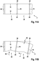
- FIG. 11A shows a schematic representation of a section of the wiper blade 2 according to the embodiment of FIG Figure 10A , in which the wiper blade 2 is in the basic position. The left end region of the wiper blade 2 is shown, in which one end of the upper part 10 and one end of the lower part 12 are fastened to the fastening part 30.
- FIG. 3 shows the first two connecting elements 18 which delimit two wiper blade elements 36 and 38. The connecting elements 18 are attached to the upper part 10 and the lower part 12 via swivel joints 20.
- FIG 11B shows a schematic representation of a section of the wiper blade 2 according to the embodiment of FIG Figure 10B , in which the wiper blade 2 is applied to the window 4.
- Pressure forces act on the lower part 12 from below from the direction of the disk Figure 10B a compressive force 40 is shown.
- the compressive force 40 causes the lower part 12 of the wiper blade element 36 to arch and bend.
- the rotary joint 20 of the first connecting element 18 is displaced to the left by a distance s.
- the second wiper blade element 38 bends downwards in the direction from which the compressive force 40 comes and hugs the window. This creates an angle 42 between the first wiper blade element 36 and the second wiper blade element 38.
- fin-ray windshield wiper device wipers for vehicle windows can be produced in a particularly favorable manner and / or for a plurality of different areas of application.
- the embodiments of the windshield wiper device described herein enable particularly good adaptation to the curvature of a windshield, so that particularly good and precise wiping of the windshield is ensured. Areas of the pane that have not been wiped and the formation of fog on the pane can largely be avoided.
- the structural design of the windshield wiper device enables a largely uniform contact pressure of the windshield wiper device on the window, so that a high wiping quality is provided.
Landscapes
- Engineering & Computer Science (AREA)
- Mechanical Engineering (AREA)
- Body Structure For Vehicles (AREA)
- Transmission Devices (AREA)
- Pivots And Pivotal Connections (AREA)
Claims (14)
- Dispositif d'essuie-glace selon le principe des rayons de nageoires, pour un véhicule, en particulier un véhicule automobile, comprenant un balai d'essuie-glace (2) comprenant- une partie supérieure allongée (10) qui est configurée sous forme au moins en partie flexible,- une partie inférieure allongée (12) qui est configurée sous forme au moins en partie flexible, et- plusieurs éléments de liaison (18) pour relier la partie supérieure (10) et la partie inférieure (12), les éléments de liaison (18) étant espacés les uns des autres le long d'une étendue longitudinale (8) du balai d'essuie-glace (2), les éléments de liaison (18) étant conçus pour permettre un déplacement de la partie supérieure (10) et de la partie inférieure l'une par rapport à l'autre avec une composante directionnelle le long d'une étendue longitudinale (8) du balai d'essuie-glace (2), les éléments de liaison (18) étant disposés par rapport à la partie inférieure (12) de telle sorte que dans un état non sollicité du balai d'essuie-étendue longitudinale (8) du balai d'essuie-glace (2).
- Dispositif d'essuie-glace selon la revendication 1, le balai d'essuie-glace (2) présentant au moins axes longitudinaux des éléments de liaison (18) par rapport à la partie inférieure (12) diminue le long d'une étendue longitudinale (8) du balai d'essuie-glace (2) jusqu'à une extrémité de balai d'essuie-glace, et le dispositif d'essuie-glace présentant au moins une deuxième région dans n des axes longitudinaux des éléments de liaison (18) par rapport à la partie inférieure (12) augmente le long d'une étendue longitudinale (8) du balai d'essuie-glace (2) jusqu'à une extrémité de balai d'essuie-glace.
- Dispositif d'essuie-glace selon la revendication 1 ou 2, dans lequel les éléments de liaison (18) sont configurés de telle sorte que la distance entre la partie supérieure (10) et la partie inférieure (12) varie au moins en partie le long d'une étendue longitudinale (8) du balai d'essuie-glace (2), en particulier de telle sorte que la distance entre la partie supérieure (10) et la partie inférieure (12), au moins en partie le long d'une étendue longitudinale (8) du balai d'essuie-glace (2), diminue et augmente en partie.
- Dispositif d'essuie-glace selon la revendication 3, dans lequel les éléments de liaison (18) sont configurés de telle sorte que la distance variable entre la partie supérieure (10) et la partie inférieure (12) le long d'une étendue longitudinale (8) du balai d'essuie-glace (2) passe, vers une extrémité de balai d'essuie-glace, par un minimum de distance.
- Dispositif d'essuie-glace selon l'une quelconque des revendications précédentes, dans lequel les éléments de liaison (18) sont reliés de manière articulée, en particulier au moyen d'une première charnière à film (20), à la partie inférieure (12) et/ou à la partie supérieure (10).
- Dispositif d'essuie-glace selon l'une quelconque des revendications précédentes, dans lequel la largeur de la partie inférieure (12) et/ou la largeur de la partie supérieure (10) le long de l'étendue longitudinale (8) du balai d'essuie-glace (2) diminue jusqu'à une extrémité de balai d'essuie-glace.
- Dispositif d'essuie-glace selon l'une quelconque des revendications précédentes, dans lequel l'épaisseur de la partie supérieure (10) le long de l'étendue longitudinale (8) du balai d'essuie-glace (2) diminue jusqu'à une extrémité de balai d'essuie-glace.
- Dispositif d'essuie-glace selon l'une quelconque des revendications précédentes, dans lequel l'épaisseur de la partie inférieure (12) le long de l'étendue longitudinale (8) du balai d'essuie-glace (2) est variable.
- Dispositif d'essuie-glace selon la revendication 8, dans lequel la partie inférieure (12) comprend plusieurs segments de partie inférieure (11) qui sont reliés les uns aux autres de manière articulée.
- Dispositif d'essuie-glace selon la revendication 9, dans lequel les segments de partie inférieure (11) sont reliés les uns aux autres au moyen d'une deuxième charnière à film (23) qui est réalisée notamment d'une seule pièce avec les segments de partie inférieure.
- Dispositif d'essuie-glace selon l'une quelconque des revendications 9 et 10, dans lequel une pluralité des éléments de liaison (18) sont reliés aux segments de partie inférieure, en particulier sont reliés entre deux des deuxièmes charnières à film.
- Dispositif d'essuie-glace selon l'une quelconque des revendications précédentes, le dispositif d'essuie-glace étant constitué d'au moins un matériau parmi le groupe suivant : POM, PA, TPE, en particulier TPE-S, TPE-O, TPE-U, TPE-A, TPE-V et TPE-E.
- Dispositif d'essuie-glace selon l'une quelconque des revendications précédentes, le dispositif d'essuie-glace étant fabriqué par un procédé de moulage par injection à deux composants.
- Dispositif d'essuie-glace selon l'une quelconque des revendications précédentes, dans lequel la courbure de la partie supérieure et/ou de la partie inférieure présente par rapport à l'étendue longitudinale un ou plusieurs changements de signes.
Applications Claiming Priority (2)
| Application Number | Priority Date | Filing Date | Title |
|---|---|---|---|
| DE102013217951.0A DE102013217951A1 (de) | 2013-09-09 | 2013-09-09 | Strukturvarianten für Fin Ray-Wischer |
| PCT/EP2014/066831 WO2015032566A1 (fr) | 2013-09-09 | 2014-08-05 | Variantes de structure pour essuie-glace à épine de nageoire |
Publications (2)
| Publication Number | Publication Date |
|---|---|
| EP3044047A1 EP3044047A1 (fr) | 2016-07-20 |
| EP3044047B1 true EP3044047B1 (fr) | 2020-10-07 |
Family
ID=51265703
Family Applications (1)
| Application Number | Title | Priority Date | Filing Date |
|---|---|---|---|
| EP14747396.1A Active EP3044047B1 (fr) | 2013-09-09 | 2014-08-05 | Variantes de structure pour essuie-glace à épine de nageoire |
Country Status (4)
| Country | Link |
|---|---|
| EP (1) | EP3044047B1 (fr) |
| DE (1) | DE102013217951A1 (fr) |
| FR (1) | FR3010372B1 (fr) |
| WO (1) | WO2015032566A1 (fr) |
Families Citing this family (1)
| Publication number | Priority date | Publication date | Assignee | Title |
|---|---|---|---|---|
| DE102018105566B4 (de) * | 2018-03-12 | 2023-03-23 | Dr. Ing. H.C. F. Porsche Aktiengesellschaft | Flexibles Auslassventil |
Family Cites Families (3)
| Publication number | Priority date | Publication date | Assignee | Title |
|---|---|---|---|---|
| DE1918917A1 (de) * | 1969-04-14 | 1970-10-15 | Richard Mueller | Druckverteilungsvorrichtung fuer Scheibenwischer,insbesondere fuer Kraftfahrzeuge |
| JPH0542020U (ja) * | 1991-11-08 | 1993-06-08 | 憲治 大垣 | 板ばね式ワイパブレード |
| CN1123466C (zh) * | 1998-10-09 | 2003-10-08 | 屈柯产品有限公司 | 挡风玻璃雨刮 |
-
2013
- 2013-09-09 DE DE102013217951.0A patent/DE102013217951A1/de not_active Withdrawn
-
2014
- 2014-08-05 WO PCT/EP2014/066831 patent/WO2015032566A1/fr not_active Ceased
- 2014-08-05 EP EP14747396.1A patent/EP3044047B1/fr active Active
- 2014-09-08 FR FR1458393A patent/FR3010372B1/fr active Active
Non-Patent Citations (1)
| Title |
|---|
| None * |
Also Published As
| Publication number | Publication date |
|---|---|
| FR3010372A1 (fr) | 2015-03-13 |
| EP3044047A1 (fr) | 2016-07-20 |
| FR3010372B1 (fr) | 2018-07-13 |
| DE102013217951A1 (de) | 2015-03-26 |
| WO2015032566A1 (fr) | 2015-03-12 |
Similar Documents
| Publication | Publication Date | Title |
|---|---|---|
| EP2917076B1 (fr) | Dispositif essuie-glace pour un véhicule | |
| WO2015071104A1 (fr) | Système d'essuie-glace | |
| EP3044045B1 (fr) | Dispositif de fixation pour dispositif essuie-glace | |
| WO2015032563A1 (fr) | Lèvre d'essuyage pour un dispositif d'essuie-glace | |
| EP3172095B1 (fr) | Système de solution rapide pour essuie-glace finray | |
| WO2016096453A1 (fr) | Dispositif d'essuie-glace | |
| EP3044047B1 (fr) | Variantes de structure pour essuie-glace à épine de nageoire | |
| WO2016012264A1 (fr) | Dispositif de fixation pour dispositif d'essuie-glace | |
| EP3172098B1 (fr) | Variante de structure pour essuie-glace fin ray | |
| EP3044051B1 (fr) | Charnière pelliculaire pour un dispositif d'essuie-glace | |
| EP3224092B1 (fr) | Essuie-glace finray à caoutchouc interchangeable | |
| EP3218234B1 (fr) | Essuie-glace finray présentant une flexostructure à déformation optimisée | |
| DE102013217945A1 (de) | Vorspannungsvorrichtung für eine Scheibenwischvorrichtung | |
| DE102014215831B4 (de) | Scheibenwischvorrichtung | |
| DE102013226456A1 (de) | Scheibenwischvorrichtung mit integrierter Reinigungs-(Jetwiper)-Funktionalität | |
| EP3044049B1 (fr) | Dispositif d'essuie-glace à comportement au fluage amélioré | |
| DE102014223920B4 (de) | Finray-Wischer mit modularem Aufbau | |
| WO2015180921A1 (fr) | Déflecteur pour essuie-glace finray | |
| WO2015113714A1 (fr) | Dispositif d'essuie-glace pour véhicule | |
| DE102013222994A1 (de) | Scheibenwischvorrichtung | |
| WO2016012266A1 (fr) | Dispositif d'essuie-glace | |
| WO2016096261A1 (fr) | Dispositif d'essuie-glace | |
| DE102015204847A1 (de) | Heckscheibenwischvorrichtung | |
| DE102014214577A1 (de) | Vorspannungsvorrichtung für eine Scheibenwischvorrichtung |
Legal Events
| Date | Code | Title | Description |
|---|---|---|---|
| PUAI | Public reference made under article 153(3) epc to a published international application that has entered the european phase |
Free format text: ORIGINAL CODE: 0009012 |
|
| 17P | Request for examination filed |
Effective date: 20160411 |
|
| AK | Designated contracting states |
Kind code of ref document: A1 Designated state(s): AL AT BE BG CH CY CZ DE DK EE ES FI FR GB GR HR HU IE IS IT LI LT LU LV MC MK MT NL NO PL PT RO RS SE SI SK SM TR |
|
| AX | Request for extension of the european patent |
Extension state: BA ME |
|
| DAX | Request for extension of the european patent (deleted) | ||
| STAA | Information on the status of an ep patent application or granted ep patent |
Free format text: STATUS: EXAMINATION IS IN PROGRESS |
|
| 17Q | First examination report despatched |
Effective date: 20190911 |
|
| GRAP | Despatch of communication of intention to grant a patent |
Free format text: ORIGINAL CODE: EPIDOSNIGR1 |
|
| STAA | Information on the status of an ep patent application or granted ep patent |
Free format text: STATUS: GRANT OF PATENT IS INTENDED |
|
| RAP1 | Party data changed (applicant data changed or rights of an application transferred) |
Owner name: ROBERT BOSCH GMBH |
|
| INTG | Intention to grant announced |
Effective date: 20200420 |
|
| GRAS | Grant fee paid |
Free format text: ORIGINAL CODE: EPIDOSNIGR3 |
|
| GRAA | (expected) grant |
Free format text: ORIGINAL CODE: 0009210 |
|
| STAA | Information on the status of an ep patent application or granted ep patent |
Free format text: STATUS: THE PATENT HAS BEEN GRANTED |
|
| AK | Designated contracting states |
Kind code of ref document: B1 Designated state(s): AL AT BE BG CH CY CZ DE DK EE ES FI FR GB GR HR HU IE IS IT LI LT LU LV MC MK MT NL NO PL PT RO RS SE SI SK SM TR |
|
| REG | Reference to a national code |
Ref country code: GB Ref legal event code: FG4D Free format text: NOT ENGLISH |
|
| REG | Reference to a national code |
Ref country code: CH Ref legal event code: EP Ref country code: AT Ref legal event code: REF Ref document number: 1320875 Country of ref document: AT Kind code of ref document: T Effective date: 20201015 |
|
| REG | Reference to a national code |
Ref country code: IE Ref legal event code: FG4D Free format text: LANGUAGE OF EP DOCUMENT: GERMAN |
|
| REG | Reference to a national code |
Ref country code: DE Ref legal event code: R096 Ref document number: 502014014856 Country of ref document: DE |
|
| REG | Reference to a national code |
Ref country code: NL Ref legal event code: MP Effective date: 20201007 |
|
| PG25 | Lapsed in a contracting state [announced via postgrant information from national office to epo] |
Ref country code: GR Free format text: LAPSE BECAUSE OF FAILURE TO SUBMIT A TRANSLATION OF THE DESCRIPTION OR TO PAY THE FEE WITHIN THE PRESCRIBED TIME-LIMIT Effective date: 20210108 Ref country code: NL Free format text: LAPSE BECAUSE OF FAILURE TO SUBMIT A TRANSLATION OF THE DESCRIPTION OR TO PAY THE FEE WITHIN THE PRESCRIBED TIME-LIMIT Effective date: 20201007 Ref country code: NO Free format text: LAPSE BECAUSE OF FAILURE TO SUBMIT A TRANSLATION OF THE DESCRIPTION OR TO PAY THE FEE WITHIN THE PRESCRIBED TIME-LIMIT Effective date: 20210107 Ref country code: PT Free format text: LAPSE BECAUSE OF FAILURE TO SUBMIT A TRANSLATION OF THE DESCRIPTION OR TO PAY THE FEE WITHIN THE PRESCRIBED TIME-LIMIT Effective date: 20210208 Ref country code: FI Free format text: LAPSE BECAUSE OF FAILURE TO SUBMIT A TRANSLATION OF THE DESCRIPTION OR TO PAY THE FEE WITHIN THE PRESCRIBED TIME-LIMIT Effective date: 20201007 Ref country code: RS Free format text: LAPSE BECAUSE OF FAILURE TO SUBMIT A TRANSLATION OF THE DESCRIPTION OR TO PAY THE FEE WITHIN THE PRESCRIBED TIME-LIMIT Effective date: 20201007 |
|
| REG | Reference to a national code |
Ref country code: LT Ref legal event code: MG4D |
|
| PG25 | Lapsed in a contracting state [announced via postgrant information from national office to epo] |
Ref country code: BG Free format text: LAPSE BECAUSE OF FAILURE TO SUBMIT A TRANSLATION OF THE DESCRIPTION OR TO PAY THE FEE WITHIN THE PRESCRIBED TIME-LIMIT Effective date: 20210107 Ref country code: ES Free format text: LAPSE BECAUSE OF FAILURE TO SUBMIT A TRANSLATION OF THE DESCRIPTION OR TO PAY THE FEE WITHIN THE PRESCRIBED TIME-LIMIT Effective date: 20201007 Ref country code: LV Free format text: LAPSE BECAUSE OF FAILURE TO SUBMIT A TRANSLATION OF THE DESCRIPTION OR TO PAY THE FEE WITHIN THE PRESCRIBED TIME-LIMIT Effective date: 20201007 Ref country code: PL Free format text: LAPSE BECAUSE OF FAILURE TO SUBMIT A TRANSLATION OF THE DESCRIPTION OR TO PAY THE FEE WITHIN THE PRESCRIBED TIME-LIMIT Effective date: 20201007 Ref country code: SE Free format text: LAPSE BECAUSE OF FAILURE TO SUBMIT A TRANSLATION OF THE DESCRIPTION OR TO PAY THE FEE WITHIN THE PRESCRIBED TIME-LIMIT Effective date: 20201007 Ref country code: IS Free format text: LAPSE BECAUSE OF FAILURE TO SUBMIT A TRANSLATION OF THE DESCRIPTION OR TO PAY THE FEE WITHIN THE PRESCRIBED TIME-LIMIT Effective date: 20210207 |
|
| PG25 | Lapsed in a contracting state [announced via postgrant information from national office to epo] |
Ref country code: HR Free format text: LAPSE BECAUSE OF FAILURE TO SUBMIT A TRANSLATION OF THE DESCRIPTION OR TO PAY THE FEE WITHIN THE PRESCRIBED TIME-LIMIT Effective date: 20201007 |
|
| REG | Reference to a national code |
Ref country code: DE Ref legal event code: R097 Ref document number: 502014014856 Country of ref document: DE |
|
| PG25 | Lapsed in a contracting state [announced via postgrant information from national office to epo] |
Ref country code: EE Free format text: LAPSE BECAUSE OF FAILURE TO SUBMIT A TRANSLATION OF THE DESCRIPTION OR TO PAY THE FEE WITHIN THE PRESCRIBED TIME-LIMIT Effective date: 20201007 Ref country code: CZ Free format text: LAPSE BECAUSE OF FAILURE TO SUBMIT A TRANSLATION OF THE DESCRIPTION OR TO PAY THE FEE WITHIN THE PRESCRIBED TIME-LIMIT Effective date: 20201007 Ref country code: SM Free format text: LAPSE BECAUSE OF FAILURE TO SUBMIT A TRANSLATION OF THE DESCRIPTION OR TO PAY THE FEE WITHIN THE PRESCRIBED TIME-LIMIT Effective date: 20201007 Ref country code: LT Free format text: LAPSE BECAUSE OF FAILURE TO SUBMIT A TRANSLATION OF THE DESCRIPTION OR TO PAY THE FEE WITHIN THE PRESCRIBED TIME-LIMIT Effective date: 20201007 Ref country code: RO Free format text: LAPSE BECAUSE OF FAILURE TO SUBMIT A TRANSLATION OF THE DESCRIPTION OR TO PAY THE FEE WITHIN THE PRESCRIBED TIME-LIMIT Effective date: 20201007 Ref country code: SK Free format text: LAPSE BECAUSE OF FAILURE TO SUBMIT A TRANSLATION OF THE DESCRIPTION OR TO PAY THE FEE WITHIN THE PRESCRIBED TIME-LIMIT Effective date: 20201007 |
|
| PLBE | No opposition filed within time limit |
Free format text: ORIGINAL CODE: 0009261 |
|
| STAA | Information on the status of an ep patent application or granted ep patent |
Free format text: STATUS: NO OPPOSITION FILED WITHIN TIME LIMIT |
|
| PG25 | Lapsed in a contracting state [announced via postgrant information from national office to epo] |
Ref country code: DK Free format text: LAPSE BECAUSE OF FAILURE TO SUBMIT A TRANSLATION OF THE DESCRIPTION OR TO PAY THE FEE WITHIN THE PRESCRIBED TIME-LIMIT Effective date: 20201007 |
|
| 26N | No opposition filed |
Effective date: 20210708 |
|
| PG25 | Lapsed in a contracting state [announced via postgrant information from national office to epo] |
Ref country code: IT Free format text: LAPSE BECAUSE OF FAILURE TO SUBMIT A TRANSLATION OF THE DESCRIPTION OR TO PAY THE FEE WITHIN THE PRESCRIBED TIME-LIMIT Effective date: 20201007 Ref country code: AL Free format text: LAPSE BECAUSE OF FAILURE TO SUBMIT A TRANSLATION OF THE DESCRIPTION OR TO PAY THE FEE WITHIN THE PRESCRIBED TIME-LIMIT Effective date: 20201007 |
|
| PG25 | Lapsed in a contracting state [announced via postgrant information from national office to epo] |
Ref country code: SI Free format text: LAPSE BECAUSE OF FAILURE TO SUBMIT A TRANSLATION OF THE DESCRIPTION OR TO PAY THE FEE WITHIN THE PRESCRIBED TIME-LIMIT Effective date: 20201007 |
|
| REG | Reference to a national code |
Ref country code: CH Ref legal event code: PL |
|
| PG25 | Lapsed in a contracting state [announced via postgrant information from national office to epo] |
Ref country code: MC Free format text: LAPSE BECAUSE OF FAILURE TO SUBMIT A TRANSLATION OF THE DESCRIPTION OR TO PAY THE FEE WITHIN THE PRESCRIBED TIME-LIMIT Effective date: 20201007 |
|
| REG | Reference to a national code |
Ref country code: BE Ref legal event code: MM Effective date: 20210831 |
|
| GBPC | Gb: european patent ceased through non-payment of renewal fee |
Effective date: 20210805 |
|
| PG25 | Lapsed in a contracting state [announced via postgrant information from national office to epo] |
Ref country code: LI Free format text: LAPSE BECAUSE OF NON-PAYMENT OF DUE FEES Effective date: 20210831 Ref country code: CH Free format text: LAPSE BECAUSE OF NON-PAYMENT OF DUE FEES Effective date: 20210831 |
|
| PG25 | Lapsed in a contracting state [announced via postgrant information from national office to epo] |
Ref country code: IS Free format text: LAPSE BECAUSE OF FAILURE TO SUBMIT A TRANSLATION OF THE DESCRIPTION OR TO PAY THE FEE WITHIN THE PRESCRIBED TIME-LIMIT Effective date: 20210207 Ref country code: LU Free format text: LAPSE BECAUSE OF NON-PAYMENT OF DUE FEES Effective date: 20210805 |
|
| PG25 | Lapsed in a contracting state [announced via postgrant information from national office to epo] |
Ref country code: IE Free format text: LAPSE BECAUSE OF NON-PAYMENT OF DUE FEES Effective date: 20210805 Ref country code: GB Free format text: LAPSE BECAUSE OF NON-PAYMENT OF DUE FEES Effective date: 20210805 Ref country code: FR Free format text: LAPSE BECAUSE OF NON-PAYMENT OF DUE FEES Effective date: 20210831 Ref country code: BE Free format text: LAPSE BECAUSE OF NON-PAYMENT OF DUE FEES Effective date: 20210831 |
|
| REG | Reference to a national code |
Ref country code: AT Ref legal event code: MM01 Ref document number: 1320875 Country of ref document: AT Kind code of ref document: T Effective date: 20210805 |
|
| PG25 | Lapsed in a contracting state [announced via postgrant information from national office to epo] |
Ref country code: AT Free format text: LAPSE BECAUSE OF NON-PAYMENT OF DUE FEES Effective date: 20210805 |
|
| PG25 | Lapsed in a contracting state [announced via postgrant information from national office to epo] |
Ref country code: HU Free format text: LAPSE BECAUSE OF FAILURE TO SUBMIT A TRANSLATION OF THE DESCRIPTION OR TO PAY THE FEE WITHIN THE PRESCRIBED TIME-LIMIT; INVALID AB INITIO Effective date: 20140805 |
|
| PG25 | Lapsed in a contracting state [announced via postgrant information from national office to epo] |
Ref country code: CY Free format text: LAPSE BECAUSE OF FAILURE TO SUBMIT A TRANSLATION OF THE DESCRIPTION OR TO PAY THE FEE WITHIN THE PRESCRIBED TIME-LIMIT Effective date: 20201007 |
|
| PG25 | Lapsed in a contracting state [announced via postgrant information from national office to epo] |
Ref country code: MK Free format text: LAPSE BECAUSE OF FAILURE TO SUBMIT A TRANSLATION OF THE DESCRIPTION OR TO PAY THE FEE WITHIN THE PRESCRIBED TIME-LIMIT Effective date: 20201007 |
|
| PG25 | Lapsed in a contracting state [announced via postgrant information from national office to epo] |
Ref country code: TR Free format text: LAPSE BECAUSE OF FAILURE TO SUBMIT A TRANSLATION OF THE DESCRIPTION OR TO PAY THE FEE WITHIN THE PRESCRIBED TIME-LIMIT Effective date: 20201007 |
|
| PG25 | Lapsed in a contracting state [announced via postgrant information from national office to epo] |
Ref country code: MT Free format text: LAPSE BECAUSE OF FAILURE TO SUBMIT A TRANSLATION OF THE DESCRIPTION OR TO PAY THE FEE WITHIN THE PRESCRIBED TIME-LIMIT Effective date: 20201007 |
|
| PGFP | Annual fee paid to national office [announced via postgrant information from national office to epo] |
Ref country code: DE Payment date: 20251021 Year of fee payment: 12 |