EP3044533B1 - Abschussblockiermechanismus für eine schusswaffe - Google Patents
Abschussblockiermechanismus für eine schusswaffe Download PDFInfo
- Publication number
- EP3044533B1 EP3044533B1 EP14865266.2A EP14865266A EP3044533B1 EP 3044533 B1 EP3044533 B1 EP 3044533B1 EP 14865266 A EP14865266 A EP 14865266A EP 3044533 B1 EP3044533 B1 EP 3044533B1
- Authority
- EP
- European Patent Office
- Prior art keywords
- blocker
- lifter
- striker
- trigger
- firearm
- Prior art date
- Legal status (The legal status is an assumption and is not a legal conclusion. Google has not performed a legal analysis and makes no representation as to the accuracy of the status listed.)
- Active
Links
Images




Classifications
-
- F—MECHANICAL ENGINEERING; LIGHTING; HEATING; WEAPONS; BLASTING
- F41—WEAPONS
- F41A—FUNCTIONAL FEATURES OR DETAILS COMMON TO BOTH SMALLARMS AND ORDNANCE, e.g. CANNONS; MOUNTINGS FOR SMALLARMS OR ORDNANCE
- F41A17/00—Safety arrangements, e.g. safeties
- F41A17/64—Firing-pin safeties, i.e. means for preventing movement of slidably- mounted strikers
- F41A17/72—Firing-pin safeties, i.e. means for preventing movement of slidably- mounted strikers trigger-operated, i.e. the movement of the trigger bringing a firing-pin safety into inoperative position during the firing
Definitions
- the present invention generally relates to firearms, and more particularly to firing mechanisms suitable for auto-loading pistols.
- Firearms such as semiautomatic auto-loading pistols come in a variety of full size and compact platforms for concealed carry applications.
- One type of firing mechanism used in pistols relies on a pivotable hammer which is held in a rear cocked and ready-to-fire position. To discharge the pistol, the hammer is released from a cocked position via a trigger pull which impacts and drives a firing pin forward to contact and detonate a chambered ammunition cartridge.
- "striker-fired" pistols have a somewhat more simplified firing mechanism which utilize a linearly movable striker that is held in a cocked position. Pulling the trigger releases the striker to directly contact and detonate a chambered ammunition round.
- a firing blocker mechanism intended to prevent discharge of a pistol or other type firearm in the absence of a trigger pull is desired.
- US 5,157,209 discloses in a semi-automatic firearm a simplified firing mechanism that includes a manual safety system and a doubly redundant automatic safety system.
- the firing mechanism includes a trigger, a trigger bar, a trigger lever, a firing pin safety, spring loaded striker with a firing pin, a sear, a dislocator and a manual safety.
- the manual safety is in the safe position, the striker is blocked and the trigger bar is disengaged from the sear and the dislocator. If the manual safety is in the firing position, but the trigger has not been fully released after each discharge, the trigger lever cannot move the firing pin safety out of the way of the striker, and the trigger bar cannot move the sear.
- US 2011/0289811 discloses a cocking/de-cocking mechanism for semi-automatic striker-fired pistols having a multi-function cocking lever for controlling by rotational movement, the cocking or arming of the tiring pin, while effecting de-cocking by the lateral displacement of the cocking lever on its support pin.
- the firearm may be a pistol.
- an auto-loading firearm with striker firing mechanism includes a longitudinal axis; a frame; a barrel defining a chamber for holding a cartridge; an elongated striker movable along the longitudinal axis in a linear path to strike a chambered cartridge; a sear pivotably disposed in the frame and configured to hold the striker in a rearward cocked position; a blocker movable from a non-blocking position to a blocking position obstructing the linear path of the striker; a blocker lifter pivotably disposed in the frame and operably linked to a trigger mechanism having a trigger; and a biasing member urging the blocker into the blocking position.
- Pulling the trigger rotates the blocker lifter which engages and moves the blocker from the blocking position to the non-blocking position allowing the firearm to be discharged.
- the rotation of the blocker lifter engages and rotates the sear to release the striker from the cocked position for discharging the firearm.
- a method for discharging a firearm includes the steps of providing a firearm having a longitudinal axis, a frame, a trigger mechanism, a striker movable forward and rearward along the longitudinal axis in a linear path, and a blocker movable into and out of the linear path; biasing the blocker into the linear path; pulling a trigger of the trigger mechanism; rotating a blocker lifter with the trigger mechanism which moves the blocker out of the linear path; rotating a sear holding the striker in a rearward cocked position to release the striker; and moving the striker in a forward direction along the linear path for discharging the firearm.
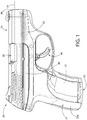
- FIG. 1 depicts a right side view of a pistol 20 showing the firing control mechanism components with the frame and slide of the pistol shown superimposed in phantom view to better reveal these components and their relative positions as mounted therein.
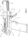
- FIG. 2 depicts pistol 20 without the slide and frame, and showing a firing control housing insert 80 which in one embodiment is removably mountable in the pistol frame as further described herein.
- FIG. 3 depicts the firing control housing insert 80 alone with firing mechanism components.
- pistol 20 includes a grip frame 22 having a rear downwardly extending grip portion 22a for grasping and a longitudinally-extending cavity 22b which opens upwards and receives firing control housing insert 80 therein.
- Firing control housing insert 80 supports various firing control mechanism components which advantageously may be mounted therein prior to inserting the insert into the frame 22 to facilitate assembly of the pistol.
- the firing control housing insert 80 with firing control mechanism components is mountable in frame 22 as a unit.
- this allows the firing control components to be pre-mounted in the insert 80 in a simplified and readily more accessible manner rather than mounting the components individually in the frame.
- the firing control mechanism components may be directly mounted in frame 22 without use of an insert 80.
- the invention is therefore expressly not limited to either arrangement.
- Slide 24 is slidably mounted on pistol 20, and in one embodiment on firing control housing 80 and/or frame 22 via a support rail and groove system for axial reciprocating movement forwards and rearwards thereon.
- Recoil spring 29 operably associated with slide 24 acts to return the slide to the forward position shown in FIG. 1 after discharging pistol 20.
- a magazine 50 may be removably inserted into frame 22 and firing control housing 80.
- the frame 22 may define a magazine well 21 with open bottom configured for receiving and supporting magazine 50 therein. Magazine 50 is sized and configured for holding and dispensing a plurality of cartridges C.
- Pistol 20 further includes a barrel 26 that is movably disposed at least partially inside slide 24 and includes a rear chamber block 28 defining an open chamber 30 therein configured for receiving a cartridge. Breech area 23 is defined at the rear of barrel 26 and chamber 30 in the slide 24 for loading cartridges C therein from magazine 50.
- Slide 24 includes a breech block defining a frontal breech face which is axially moveable with the slide in relation to the chamber 30 to alternatingly form an open or closed breech in a manner well known in the art.
- Pistol 20 further includes a longitudinal axis LA defining an axial direction and which is approximately concentrically aligned with barrel 26 and slide 24 as shown in FIG.
- Barrel 26 is moveable rearwards with slide 24 on firing control housing 80 under recoil after discharging pistol 20 in one embodiment, In other embodiments, the barrel 26 may remain stationary after discharging the pistol. Slide is movable rearwards on frame 22 under recoil or when manually cycling the action.
- FIGS. 4-6 show firing control components disembodied from the pistol grip frame 22 and firing control housing insert 80 for clarity.
- a firing control mechanism in one embodiment includes a trigger assembly including a trigger 40 pivotally mounted in frame 22 to firing control housing 80 via transverse pin 41 and an axially (longitudinally) movable trigger bar 42 pivotally coupled to the trigger via transverse pin 43 on an upward trigger pivot extension 46. Pulling trigger 40 rearward moves trigger bar 42 axially forward.
- Striker spring 64 may be positioned concentrically around the axially elongated striker 65. Striker spring 64 may be a. helical compression coil spring in one embodiment, or other suitable type spring operable to bias the striker 65 forwards towards the chamber 30. Striker may have a diametrically narrowed front end 66 configured to contact the rear of cartridge C for detonating the cartridge.
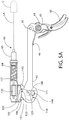
- a trigger return spring 44 may further be provided which in one embodiment may be a torsion spring that is mounted about trigger pin 41 and biases trigger 40 toward the fully forward ready-to-fire position shown in FIGS. 1 and 5A .
- Trigger spring 44 may further include a rearwardly extending leg 45 with a lateral extension which acts on the underside of trigger bar 42 to bias the trigger bar upwards towards engagement with hammer 60.
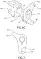
- leg 45 may be axially and movably disposed in an elongated slot or recess 145 formed in the underside of trigger bar 42 as best shown in FIG. 6B to help maintain positive engagement between spring 44 and the trigger bar.
- the firing control system or mechanism may further include a sear 100, a blocker 120, and blocker lifter 140.
- the blocker Lifter 140 operably engages both the sear 100 and trigger bar 42 on opposite lateral sides to link the trigger mechanism to the striker 65 for firing the pistol 20.
- Sear 100 is pivotably mounted to firing control housing insert 80 via a transverse sear mounting pin 102 and biased in a clockwise direction as viewed in FIGS. 4-6 by sear spring 104.
- sear spring 104 may include a forward extending leg 104a configured to engage the blocker actuating arm 142 of blocker lifter 140. This biases the blocker actuating arm 142 into a forward and downward position so that the blocker 120 is not pushed upward and deactivated in the absence of a trigger pull.
- Sear 100 includes an upper rear facing striker catch surface 106 engageable with downward extending striker catch protrusion 150 on striker 65 and a lower rear facing operating surface 108 engageable by a corresponding forward facing operating surface 146 on blocker lifter 140 for rotating the sear, as further described herein.
- upper striker catch surface 106 may be disposed at least partially above or at the same elevation and to the rear of sear mounting pin 102 for movement in a downward and rearward counterclockwise direction (as viewed in FIGS. 4-6 ) when releasing the striker 65.
- the lower surface 108 may be disposed at least partially below the sear mounting pin 102 for movement in an opposing upwards and forward counterclockwise direction by the blocker lifter 140.
- upper and lower surfaces 106, 108 are disposed at opposing top and bottom ends of sear 100, respectively.
- operating surface 146 on blocker lifter 140 may be formed on a laterally extending protrusion 141 which is received in rearwardly open recess 126 in sear 100.
- Lower rear facing operating surface 108 of sear 100 may be disposed within the recess 126.
- This foregoing arrangement provides for partial nesting of a portion of blocker lifter 140 in sear 100 which allows the blocker lifter to operate and rotate the sear to release the striker 65 for discharging pistol 20.
- sear 100 is only operated by the blocker lifter 140 and not directly by the trigger bar 42 which acts directly on the blocker lifter.
- the main body of blocker lifter 140 may laterally abut the main body of sear 100 in one arrangement.
- Blocker lifter 140 may be pivotably mounted to firing control housing insert 80 on the same axis of rotation as sear 100 by sharing sear mounting pin 102.
- the sear and blocker lifter may therefore include concentrically aligned transverse holes which receive pin 102 therethrough and one or both ends of the pin may engage the firing control housing insert 80. This conserves space and promotes efficient and uniform rotational movement of the blocker lifter and sear 100.
- blocker lifter 140 may be mounted via a separate transverse pin to firing control housing insert 80.
- Blocker lifter 140 includes a forward extending blocker actuating arm 142 configured and arranged to engage and raise the blocker 120 via a trigger pull.
- actuating arm 142 extends forward of sear mounting pin 102 (and slightly upward) at a top end of the blocker lifter 140 and defines a generally upward facing bearing surface 142a which engages a bottom facing surface 127 on the underside of the blocker 120.
- bearing surface 142a may be arcuately and convexly shaped forming a cam for smoothly engaging bottom surface 127 of the blocker 120 which acts as a cam follower reciprocating linearly upward/downward upon actuation by the blocker lifter 140 as further described herein.
- actuating post 144 of blocker lifter 140 which is configured and arranged to engage the trigger bar 42 for rotating the blocker lifter 140.
- Actuating post 144 may be disposed proximate to an opposite bottom end of the blocker lifter 140.
- actuating post 144 projects transversely through an elongated opening or slot 82 in one lateral side of the firing control housing insert 80 to engage the trigger bar which may be mounted externally on the firing control housing insert in some configurations (see, e.g. FIG. 2 ).
- trigger bar 42 may be a generally flat and relatively thin plate-like structure having an elongated configuration.
- the rear end portion of trigger bar 42 may be enlarged in height having a generally bulbous shape and further defines an axially elongated operating window 67 configured to receive and engage at least a portion of blocker lifter actuating post 144 therein for rotating the blocker lifter 140 via puling trigger 40 rearward.
- the bottom surface 110 of trigger bar operating window 67 includes a notched portion 111 which engages at least a portion of the blocker lifter actuating post 144 therein to impart the desired motion to the blocker lifter 140.
- the notched portion may extend below bottom surface 110 of the window 67 to form a receptacle for the actuating post 144 and may have an axial length just slightly larger than actuator post 144 to eliminate excessive play of the post within the notched portion 111 when pulling the trigger 40.
- Window 67 further interacts with actuating post 144 of blocker litter 140 to provide a vertical stop for limiting the upward position of trigger bar 42 under the biasing force of trigger spring 44 via the bottom surface of notched portion 111 in window 67 engaging the post 144, as best shown in FIGS. 4-6 .
- Blocker 120 is vertically movable in a linear manner transverse to the longitudinal axis LA between an lower blocking position and upper non-blocking position with respect to the striker 65.
- the blocking position see, e.g. FIGS. 4 and 5A
- a portion of the blocker 120 it positioned to engage or engages and arrests the forward axial motion of the striker 65 (parallel to the longitudinal axis LA) by a linear distance sufficient to prevent striking of a chambered ammunition cartridge C.
- the non-blocking position the blocker allows the striker 65 to move axially forward by a greater linear distance sufficient to reach and detonate the chambered cartridge C. Accordingly, the striker 65 is only permitted to move forward through a partial range of motion when the blocker 120 is in the blocking position as opposed to a full range of motion when the blocker is in the non-blocking position sufficient to strike the cartridge C.
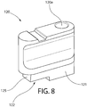
- blocker 120 includes a lower blocking extension or portion 121 which extends downwards and is configured to move at least partially into and out of the forward Linear path traveled by the striker catch protrusion 150 when the striker is released by a trigger pull to discharge the pistol 20.
- Blocking portion 121 may include a rear notch 122 which defines a shoulder 123 and a rear facing blocking surface 125 arranged to engage a corresponding forward facing engagement surface 152 of the striker catch protrusion 150 when the blocker 120 is in the blocking position.
- blocker 120 arrests the forward motion of the striker 65 by an amount sufficient to prevent the front end 66 from reaching and striking a chambered cartridge C.
- the blocking surface 125 engages a lateral extension 151 on the striker catch protrusion 150 which extends laterally outwards transversely from the axial centerline of the striker 65 which is concentrically aligned with the longitudinal axis LA of pistol 20 and chamber 30 of the barrel 26.
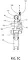
- blocker 120 may be normally biased downwardly into the activated blocking position (see, e.g. FIGS. 4 and 5C ) by spring 124.
- spring 124 may be a compression spring which acts on the top of blocker 120 such as in hole 120a (see, e.g. FIG. 8 ).
- Blocker 120 and spring 124 may be supported by slide 24 along with the striker 65.
- the blocker 120 may be located in any suitable position in pistol 20.
- blocker 120 may be located on the same lateral side of the striker 65 as the blocker lifter 140 as shown in FIGS. 4-6 for actuation by the blocker actuating arm 142.
- Other suitable mounting positions and arrangements of blocker 120 are possible.
- FIGS. 4-8 Operation of the firing control and blocker mechanism will now be described. General reference is made to FIGS. 4-8 .
- striker 65 is shown cocked rearwards. At least a portion of striker catch protrusion 150 is in axial alignment with striker catch surface 106 on sear 100 which engages and holds the striker rearward against the forward biasing force of striker spring 64.
- Blocker 120 is in the activated blocking position wherein rear facing blocking surface 125 is axially aligned to engage forward facing engagement surface 152 of the striker catch protrusion 150 should the striker 65 be somehow released in the absence of a trigger pull. The blocker 120, therefore, will prevent striker 65 from traveling forward a sufficient amount to reach and detonate a chambered cartridge C.
- Pulling trigger 40 causes a protruding upper portion or lever 140 of the trigger containing transverse pin 43 to rotate forward about trigger pin 41 and similarly pulls trigger bar 42 axially forward.
- trigger bar 42 moves forward, it pulls blocker lifter actuation post 144 positioned in notched portion 111 of trigger bar operating window 67 correspondingly forward.
- This rotates the blocker lifter 140 forward and counter-clockwise (as viewed in FIGS. 4-6 ), concomitantly raising blocker lifter actuator arm 142 (with upward facing surface 142a thereon) upwards to engage and bear on bottom facing surface 127 on the underside of the blocker 120.
- Blocker lifter 140 raises the blocker 120 upwards against the biasing force of spring 124 to a higher non-blocking position by a distance sufficient so that forward facing engagement surface 152 on striker catch protrusion 150 is no longer axially aligned with any portion of rear facing blocking surface 125 on blocker 120 along the forward linear travel path of lateral extension 151 on the striker catch protrusion.
- Blocker 120 is deactivated temporarily.
- the striker 65 is now free to move axially forward by a distance sufficient to reach and strike a chambered cartridge C.
- laterally extending protrusion 141 on blocker lifter 140 fully engages rear facing operating surface 108 on sear 100 by continued counter-clockwise rotation of the blocker lifter. This mutual engagement in turn causes the sear 100 to rotate counter-clockwise about sear pin 102.
- Striker catch surface 106 (rear facing) on striker 100 concomitantly rotates rearward and downwards (counter-clockwise as viewed in FIGS. 4-6 ), and breaks contact with downward extending striker catch protrusion 150 on striker 65. Striker 65 is released and travels axially forward rapidly by a distance sufficient to strike and detonate a chambered cartridge C, wherein the pistol 20 is discharged (see, e.g. FIG.
- Lateral extension 151 on the striker catch protrusion 150 travels forward past blocking surface 125 along the blocker 120 below and within notch 122 during this motion of the striker 65, and may engage shoulder 123 after striking the cartridge which acts as a forward-most travel stop for the striker.
- Notch 122 has an axial length sufficient to allow the striker 65 to reach a chambered cartridge C.
- the firing control mechanism After pistol 20 has been discharged, the firing control mechanism returns to the ready-to-fire position shown in FIG. 5A under the biasing force of recoil spring 29.
- Trigger 40 and trigger bar 42 return to their pre-discharge ready-to-fire positions.
- the sear 100 returns to the ready-to-fire position and holds sear 65 again in a rearward cocked position.
- Striker blocker 120 similarly returns downward to its normal lower activated blocking position in which rear facing blocking surface 125 is again axially aligned to engage forward facing engagement surface 152 of the striker catch protrusion 150 along the travel path of the catch protrusion.
Landscapes
- Engineering & Computer Science (AREA)
- General Engineering & Computer Science (AREA)
- Toys (AREA)
Claims (11)
- Selbstladende Schusswaffe mit Schlagbolzen-Abfeuerungsmechanismus, die Folgendes umfasst:eine Längsachse (LA),ein Griffstück (22),einen Lauf (26), der eine Kammer (30) zum Halten einer Patrone (C) definiert,einen länglichen Schlagbolzen (65), der in einer linearen Bahn entlang der Längsachse beweglich ist, um eine in die Kammer geladene Patrone (C) anzuschlagen,ein Abzugsstück (100), das schwenkbar im Griffstück angeordnet und dafür konfiguriert ist, den Schlagbolzen in einer nach hinten gespannten Stellung zu halten,eine Sperre (120), die von einer nicht sperrenden Stellung zu einer sperrenden Stellung, welche die lineare Bahn des Schlagbolzens sperrt, beweglich ist,einen Sperrenheber (140), der im Griffstück angeordnet und wirksam mit einem Abzugs- (40) Mechanismus, der einen Abzug (40) aufweist, verknüpft ist, undein Vorspannelement, das die Sperre in die sperrende Stellung drängt,wobei ein Ziehen des Abzugs den Sperrenheber dreht, was die Sperre in Eingriff nimmt und von der sperrenden Stellung zur nicht sperrenden Stellung bewegt, was ermöglicht, dass die Schusswaffe abgefeuert wird,wobei eine Drehung des Sperrenhebers das Abzugsstück in Eingriff nimmt und dreht, um den Schlagbolzen zum Abfeuern der Schusswaffe aus der gespannten Stellung freizugeben.
- Schusswaffe nach Anspruch 1, wobei der Sperrenheber eine erste Fläche, die mit der Sperre in Eingriff gebracht werden kann, und eine zweite Fläche, die mit dem Abzugsstück in Eingriff gebracht werden kann, aufweist und wahlweise
wobei die erste und die zweite Fläche unterhalb einer Schwenkachse des Sperrenhebers angeordnet sind. - Schusswaffe nach Anspruch 1, wobei das Abzugsstück und der Sperrenheber schwenkbar auf einer gemeinsamen Schwenkachse angebracht sind.
- Schusswaffe nach Anspruch 1, wobei der Sperrenheber einen sich nach vorn erstreckenden Betätigungsarm (142) umfasst, der eine nach oben zeigende Fläche definiert, die eine nach unten zeigende Fläche (127) auf einer Unterseite der Sperre in Eingriff nimmt.
- Schusswaffe nach Anspruch 1, wobei der Sperrenheber einen sich seitlich erstreckenden Betätigungstempel (144) einschließt, der dafür angeordnet ist, zum Drehen des Sperrenhebers über ein Ziehen des Abzugs (40) die Abzugsstange in Eingriff zu nehmen.
- Schusswaffe nach Anspruch 1, wobei der Sperrenheber seitlich angrenzend an das Abzugsstück angeordnet ist, wobei der Sperrenheber dafür konfiguriert ist, das Abzugsstück auf eine derartige Weise in Eingriff zu nehmen, dass ein Drehen des Sperrenhebers gleichzeitig das Abzugsstück dreht, um den Schlagbolzen aus der gespannten Stellung freizugeben, und wahlweise
wobei das Abzugsstück einen nach hinten offene Aussparung (126) einschließt, die zum Drehen des Abzugsstücks einen seitlichen Vorsprung des Sperrenhebers aufnimmt und in Eingriff nimmt. - Schusswaffe nach Anspruch 1, wobei die Sperre linear in einer vertikalen Richtung zwischen der nicht sperrenden und der sperrenden Stellung beweglich ist und
die ferner einen unteren Sperrfortsatz (121) umfasst, der sich von der Sperre nach unten erstreckt, wobei der Sperrfortsatz eine hintere Sperrfläche (125) definiert, die dafür angeordnet ist, eine entsprechende nach vorn zweigende Eingriffsfläche (152) eines Schlagbolzen-Fangvorsprungs (150) in Eingriff zu nehmen, wenn sich die Sperre in der sperrenden Stellung befindet, um eine Vorwärtsbewegung des Schlagbolzens anzuhalten. - Schusswaffe nach Anspruch 1, die ferner einen hin- und hergehenden Verschluss (24) umfasst, der verschiebbar auf dem Griffstück angeordnet ist.
- Verfahren zum Abfeuern einer Schusswaffe, das Folgendes umfasst:Bereitstellen einer Schusswaffe, die eine Längsachse (LA), ein Griffstück, einen Abzugs- (40) Mechanismus, einen Schlagbolzen (64), der in einer linearen Bahn entlang der Längsachse nach vorn und nach hinten beweglich ist, und eine Sperre, die in die lineare Bahn und aus derselben beweglich ist, aufweist,Vorspannen der Sperre in die lineare Bahn,Ziehen eines Abzugs (40) des Abzugsmechanismus,Drehen eines Sperrenhebers (140) mit dem Abzugsmechanismus, was die Sperre aus der linearen Bahn bewegt,Drehen eines Abzugsstücks (100), das den Schlagbolzen in einer hinteren gespannten Stellung hält, um den Schlagbolzen freizugeben, undBewegen des Schlagbolzens in einer Vorwärtsrichtung entlang der linearen Bahn zum Abfeuern der Schusswaffe,wobei der Sperrenheber das Abzugsstück durch Drehen des Sperrenhebers mit dem Abzugsmechanismus in Eingriff nimmt und dreht.
- Verfahren nach Anspruch 9, wobei sich die Sperre in einer vertikalen linearen Richtung zwischen einer sperrenden Stellung in der linearen Bahn und einer nicht sperrenden Stellung außerhalb der linearen Bahn bewegt.
- Verfahren nach Anspruch 9, wobei der Abzug eine Abzugs- (40) Stange, die mit dem Sperrenheber in Eingriff steht, in einer axialen Vorwärtsrichtung bewegt, um den Sperrenheber zu drehen.
Applications Claiming Priority (2)
| Application Number | Priority Date | Filing Date | Title |
|---|---|---|---|
| US201361875962P | 2013-09-10 | 2013-09-10 | |
| PCT/US2014/054752 WO2015080775A1 (en) | 2013-09-10 | 2014-09-09 | Firing blocker mechanism for firearm |
Publications (3)
| Publication Number | Publication Date |
|---|---|
| EP3044533A1 EP3044533A1 (de) | 2016-07-20 |
| EP3044533A4 EP3044533A4 (de) | 2017-07-19 |
| EP3044533B1 true EP3044533B1 (de) | 2018-10-24 |
Family
ID=52624136
Family Applications (1)
| Application Number | Title | Priority Date | Filing Date |
|---|---|---|---|
| EP14865266.2A Active EP3044533B1 (de) | 2013-09-10 | 2014-09-09 | Abschussblockiermechanismus für eine schusswaffe |
Country Status (3)
| Country | Link |
|---|---|
| US (1) | US9222745B2 (de) |
| EP (1) | EP3044533B1 (de) |
| WO (1) | WO2015080775A1 (de) |
Families Citing this family (22)
| Publication number | Priority date | Publication date | Assignee | Title |
|---|---|---|---|---|
| EP3129739B1 (de) * | 2014-04-11 | 2018-12-05 | Sturm, Ruger & Company, Inc. | Abzugssystem für feuerwaffen |
| US9410760B2 (en) * | 2014-07-30 | 2016-08-09 | Double Nickel Holdings, Llc | Sear assembly for hammerless, striker fired handgun |
| SK288609B6 (sk) * | 2015-05-25 | 2018-11-05 | Grand Power, S.R.O. | Spúšťový mechanizmus samonabíjacej zbrane bez bicieho kladiva s priamobežným úderníkom a samonabíjacia zbraň |
| US10739095B2 (en) | 2015-12-01 | 2020-08-11 | Mean L.L.C. | Firearm operating system |
| WO2017164950A2 (en) * | 2015-12-28 | 2017-09-28 | Sturm, Ruger & Company, Inc. | Variable barrel camming system for firearm |
| AT15313U1 (de) * | 2016-04-15 | 2017-05-15 | Bubits Gmbh | Pistole mit Sicherheitsabzug |
| USD853517S1 (en) | 2016-10-21 | 2019-07-09 | Taurus International Manufacturing, Inc. | Firearm with magazine |
| US12480740B2 (en) | 2017-12-27 | 2025-11-25 | Magpul Industries Corp. | Two-part folding trigger for a folding firearm |
| US10443971B2 (en) | 2017-12-27 | 2019-10-15 | Magpul Industries Corp. | Foldable firearm |
| US10976124B2 (en) | 2018-10-18 | 2021-04-13 | Savage Arms, Inc. | Adjustable force trigger mechanism |
| US11280570B2 (en) | 2019-03-11 | 2022-03-22 | James Matthew Underwood | Firearm operating mechanisms and bolt release |
| US11371789B2 (en) | 2019-08-06 | 2022-06-28 | James Matthew Underwood | Roller delayed firearm operating system |
| US11578939B2 (en) * | 2020-02-12 | 2023-02-14 | Sturm, Ruger & Company, Inc. | Safety mechanism for firearms |
| IT202000003695A1 (it) * | 2020-02-21 | 2021-08-21 | Tecnostudio Eng Di Ghitti Marco | Pistola |
| US11543195B2 (en) | 2020-07-03 | 2023-01-03 | James Matthew Underwood | Roller and bearing delayed firearm operating systems |
| HU231485B1 (hu) * | 2021-03-17 | 2024-02-28 | Gestamen Kutatás Fejlesztés Zártkörűen Működő Részvénytársaság | Kettős elsütési rendszerű félautomata pisztoly |
| USD1069016S1 (en) | 2021-06-02 | 2025-04-01 | Magpul Industries Corp. | Folding gun |
| US11846476B2 (en) | 2021-10-07 | 2023-12-19 | James Matthew Underwood | Ejector for firearm |
| USD1085314S1 (en) | 2021-12-20 | 2025-07-22 | Magpul Industries Corp. | Folding gun |
| TR2023001948A2 (tr) | 2022-02-22 | 2023-09-21 | Hs Produkt D O O | Manüel başparmak emni̇yeti̇ |
| WO2023250195A1 (en) * | 2022-06-23 | 2023-12-28 | Crosman Corporation | Action for low energy projectile launcher |
| US12571602B2 (en) * | 2023-11-13 | 2026-03-10 | Shadow Systems LLC | Trigger assembly |
Family Cites Families (36)
| Publication number | Priority date | Publication date | Assignee | Title |
|---|---|---|---|---|
| US2296998A (en) | 1939-04-25 | 1942-09-29 | Ernest F Koehler | Firearm |
| US3726040A (en) | 1970-06-10 | 1973-04-10 | Rolamite Inc | Gun trigger mechanism |
| DE2212211C3 (de) | 1972-03-14 | 1978-08-10 | Fa. Carl Walther, 7900 Ulm | Schlagbolzensicherungseinrichtung für Handfeuerwaffen |
| US3960053A (en) | 1974-09-20 | 1976-06-01 | Maremont Corporation | Automatic firearm having anti-bounce sear |
| US4575963A (en) * | 1984-06-25 | 1986-03-18 | Sturm, Ruger & Company, Inc. | Pistol mechanism for blocking firing pin |
| US4999939A (en) | 1987-12-31 | 1991-03-19 | Springfield Armory, Inc. | Breech load pistol and conversion |
| US4936035A (en) | 1987-12-31 | 1990-06-26 | Springfield Armory, Inc. | Breech load pistol and conversion |
| US4914845A (en) | 1987-12-31 | 1990-04-10 | Springfield Armory, Inc. | Breech load pistol and conversion |
| AT389760B (de) | 1988-03-14 | 1990-01-25 | Steyr Daimler Puch Ag | Abzugsvorrichtung, insbesondere fuer sportpistolen |
| US5088222A (en) | 1991-02-04 | 1992-02-18 | Springfield Armory, Inc. | Firearm safety |
| US5157209A (en) | 1991-12-23 | 1992-10-20 | Dunn Peter B | Semi-automatic safety handgun |
| US5259138A (en) | 1992-08-03 | 1993-11-09 | Colt's Manufacturing Company Inc. | Firing mechanism blocking system |
| US5502914A (en) | 1993-06-25 | 1996-04-02 | Moon; Kook-Jin | Striker cocking and firing mechanism for a handgun |
| US5386659A (en) * | 1993-12-17 | 1995-02-07 | Smith & Wesson Corp. | Fire control mechanism for semiautomatic pistols |
| US5438784A (en) | 1994-08-19 | 1995-08-08 | Smith & Wesson Corp. | Magazine safety |
| US5615507A (en) | 1995-06-07 | 1997-04-01 | Thompson Intellectual Properties, Ltd. | Fire control mechanism for a firearm |
| DE19737153C2 (de) | 1997-08-26 | 1999-08-26 | Sig Schweiz Industrieges | Sicherungseinrichtung für den Abzug und den Verschluss eines Jagdgewehres |
| US6119387A (en) | 1998-05-11 | 2000-09-19 | Butters; John T. | Trigger safety mechanism |
| US6601331B2 (en) | 2000-04-12 | 2003-08-05 | Alfred W. Salvitti | Integrated manual safety device for hammerless semiautomatic pistols |
| US6374526B1 (en) | 2000-05-18 | 2002-04-23 | Smith & Wesson Corp. | Firing pin block for pistol |
| US6510641B1 (en) | 2000-09-15 | 2003-01-28 | Arthur Viani | Trigger and firing pin locking system |
| BR0301483B1 (pt) * | 2003-05-23 | 2014-01-07 | Dispositivo de segurança no mecanismo de disparo para pistolas semi-automáticas de dupla-ação com percussor lançado | |
| WO2005033613A2 (en) * | 2003-07-01 | 2005-04-14 | Sigarms, Inc. | Method and device for providing an integral firearms safety lock mechanism |
| US7234261B2 (en) | 2004-04-15 | 2007-06-26 | Sturm, Ruger & Co., Inc. | Pistol with lockable manual safety mechanism |
| US7243453B2 (en) * | 2004-04-15 | 2007-07-17 | Sturm, Ruger & Company, Inc. | Pistol with firing pin locking mechanism |
| US7617628B2 (en) | 2004-12-22 | 2009-11-17 | Smith & Wesson Corp. | Fire control mechanism for a firearm |
| US7703230B2 (en) * | 2004-12-22 | 2010-04-27 | Smith & Wesson Corp. | Positive striker lock safety for use with a firearm |
| US7600340B2 (en) | 2004-12-22 | 2009-10-13 | Smith & Wesson Corp. | Locking apparatus for a firearm |
| US8109023B2 (en) | 2006-11-15 | 2012-02-07 | Dov Pikielny | Shot counter |
| US7866077B2 (en) | 2007-01-10 | 2011-01-11 | Smith & Wesson Corp. | Striker assembly for use with a firearm |
| US8245426B2 (en) | 2007-02-07 | 2012-08-21 | Dov Pikielny | Firearm with loaded / un-loaded identification system |
| US8276302B2 (en) * | 2008-12-30 | 2012-10-02 | Smith & Wesson Corp. | Manual slide and hammer lock safety for a firearm |
| US8572878B2 (en) | 2010-05-28 | 2013-11-05 | Beretta Usa Corp. | De-cocking mechanism for striker-fired semi-automatic pistols |
| DE102010050904B3 (de) | 2010-11-10 | 2012-02-09 | Carl Walther Gmbh | Abzug-System |
| US8863424B2 (en) | 2011-03-08 | 2014-10-21 | Extreme Shooting Products Ltd | Sear for converting a pull trigger into a release trigger |
| TR201808298T4 (tr) * | 2014-05-23 | 2018-07-23 | Fabbrica Darmi Pietro Beretta S P A | Geliştirilmiş kurma elemanına sahip olan bir ateşli silah. |
-
2014
- 2014-09-09 WO PCT/US2014/054752 patent/WO2015080775A1/en not_active Ceased
- 2014-09-09 EP EP14865266.2A patent/EP3044533B1/de active Active
- 2014-09-09 US US14/481,318 patent/US9222745B2/en active Active
Non-Patent Citations (1)
| Title |
|---|
| None * |
Also Published As
| Publication number | Publication date |
|---|---|
| US9222745B2 (en) | 2015-12-29 |
| WO2015080775A1 (en) | 2015-06-04 |
| US20150068092A1 (en) | 2015-03-12 |
| EP3044533A4 (de) | 2017-07-19 |
| EP3044533A1 (de) | 2016-07-20 |
Similar Documents
| Publication | Publication Date | Title |
|---|---|---|
| US9222745B2 (en) | Firing blocker mechanism for firearm | |
| EP3397916B1 (de) | Abfeuerungskontrollsystem für schusswaffe | |
| EP3129739B1 (de) | Abzugssystem für feuerwaffen | |
| US11598597B2 (en) | Safety mechanism for firearms | |
| US7698845B2 (en) | Double action model 1911 pistol | |
| EP2661600B1 (de) | Magazinentnahmemechanismus für eine schusswaffe | |
| US7581345B2 (en) | Method for blocking discharge of firearm | |
| EP2203704B1 (de) | Schlittenfangejektoranordnung für eine schusswaffe | |
| US20140165442A1 (en) | Slide takedown system and method for firearm | |
| US11578939B2 (en) | Safety mechanism for firearms | |
| EP1586850B1 (de) | Pistole mit entferntes-Magazin-Sicherheit | |
| US20220397359A1 (en) | Single-action trigger | |
| KR20200128525A (ko) | 화기를 위한 방아쇠 장치 | |
| EP0719403B1 (de) | Feuerwaffe mit versetztem nockenmechanismus | |
| EP1999819A2 (de) | Spannabzugpistole modell 1911 | |
| CA2590831A1 (en) | Double action model 1911 pistol |
Legal Events
| Date | Code | Title | Description |
|---|---|---|---|
| PUAI | Public reference made under article 153(3) epc to a published international application that has entered the european phase |
Free format text: ORIGINAL CODE: 0009012 |
|
| 17P | Request for examination filed |
Effective date: 20160301 |
|
| AK | Designated contracting states |
Kind code of ref document: A1 Designated state(s): AL AT BE BG CH CY CZ DE DK EE ES FI FR GB GR HR HU IE IS IT LI LT LU LV MC MK MT NL NO PL PT RO RS SE SI SK SM TR |
|
| AX | Request for extension of the european patent |
Extension state: BA ME |
|
| DAX | Request for extension of the european patent (deleted) | ||
| RIC1 | Information provided on ipc code assigned before grant |
Ipc: F41A 17/72 20060101AFI20170308BHEP |
|
| A4 | Supplementary search report drawn up and despatched |
Effective date: 20170616 |
|
| RIC1 | Information provided on ipc code assigned before grant |
Ipc: F41A 17/72 20060101AFI20170609BHEP |
|
| GRAP | Despatch of communication of intention to grant a patent |
Free format text: ORIGINAL CODE: EPIDOSNIGR1 |
|
| STAA | Information on the status of an ep patent application or granted ep patent |
Free format text: STATUS: GRANT OF PATENT IS INTENDED |
|
| INTG | Intention to grant announced |
Effective date: 20180614 |
|
| GRAS | Grant fee paid |
Free format text: ORIGINAL CODE: EPIDOSNIGR3 |
|
| GRAA | (expected) grant |
Free format text: ORIGINAL CODE: 0009210 |
|
| STAA | Information on the status of an ep patent application or granted ep patent |
Free format text: STATUS: THE PATENT HAS BEEN GRANTED |
|
| AK | Designated contracting states |
Kind code of ref document: B1 Designated state(s): AL AT BE BG CH CY CZ DE DK EE ES FI FR GB GR HR HU IE IS IT LI LT LU LV MC MK MT NL NO PL PT RO RS SE SI SK SM TR |
|
| REG | Reference to a national code |
Ref country code: CH Ref legal event code: EP |
|
| REG | Reference to a national code |
Ref country code: IE Ref legal event code: FG4D |
|
| REG | Reference to a national code |
Ref country code: AT Ref legal event code: REF Ref document number: 1057204 Country of ref document: AT Kind code of ref document: T Effective date: 20181115 |
|
| REG | Reference to a national code |
Ref country code: DE Ref legal event code: R096 Ref document number: 602014034857 Country of ref document: DE |
|
| REG | Reference to a national code |
Ref country code: CH Ref legal event code: NV Representative=s name: SERVOPATENT GMBH, CH |
|
| REG | Reference to a national code |
Ref country code: NL Ref legal event code: MP Effective date: 20181024 |
|
| REG | Reference to a national code |
Ref country code: LT Ref legal event code: MG4D |
|
| PG25 | Lapsed in a contracting state [announced via postgrant information from national office to epo] |
Ref country code: NL Free format text: LAPSE BECAUSE OF FAILURE TO SUBMIT A TRANSLATION OF THE DESCRIPTION OR TO PAY THE FEE WITHIN THE PRESCRIBED TIME-LIMIT Effective date: 20181024 |
|
| PG25 | Lapsed in a contracting state [announced via postgrant information from national office to epo] |
Ref country code: HR Free format text: LAPSE BECAUSE OF FAILURE TO SUBMIT A TRANSLATION OF THE DESCRIPTION OR TO PAY THE FEE WITHIN THE PRESCRIBED TIME-LIMIT Effective date: 20181024 Ref country code: PL Free format text: LAPSE BECAUSE OF FAILURE TO SUBMIT A TRANSLATION OF THE DESCRIPTION OR TO PAY THE FEE WITHIN THE PRESCRIBED TIME-LIMIT Effective date: 20181024 Ref country code: LV Free format text: LAPSE BECAUSE OF FAILURE TO SUBMIT A TRANSLATION OF THE DESCRIPTION OR TO PAY THE FEE WITHIN THE PRESCRIBED TIME-LIMIT Effective date: 20181024 Ref country code: NO Free format text: LAPSE BECAUSE OF FAILURE TO SUBMIT A TRANSLATION OF THE DESCRIPTION OR TO PAY THE FEE WITHIN THE PRESCRIBED TIME-LIMIT Effective date: 20190124 Ref country code: ES Free format text: LAPSE BECAUSE OF FAILURE TO SUBMIT A TRANSLATION OF THE DESCRIPTION OR TO PAY THE FEE WITHIN THE PRESCRIBED TIME-LIMIT Effective date: 20181024 Ref country code: IS Free format text: LAPSE BECAUSE OF FAILURE TO SUBMIT A TRANSLATION OF THE DESCRIPTION OR TO PAY THE FEE WITHIN THE PRESCRIBED TIME-LIMIT Effective date: 20190224 Ref country code: BG Free format text: LAPSE BECAUSE OF FAILURE TO SUBMIT A TRANSLATION OF THE DESCRIPTION OR TO PAY THE FEE WITHIN THE PRESCRIBED TIME-LIMIT Effective date: 20190124 Ref country code: LT Free format text: LAPSE BECAUSE OF FAILURE TO SUBMIT A TRANSLATION OF THE DESCRIPTION OR TO PAY THE FEE WITHIN THE PRESCRIBED TIME-LIMIT Effective date: 20181024 Ref country code: FI Free format text: LAPSE BECAUSE OF FAILURE TO SUBMIT A TRANSLATION OF THE DESCRIPTION OR TO PAY THE FEE WITHIN THE PRESCRIBED TIME-LIMIT Effective date: 20181024 |
|
| PG25 | Lapsed in a contracting state [announced via postgrant information from national office to epo] |
Ref country code: GR Free format text: LAPSE BECAUSE OF FAILURE TO SUBMIT A TRANSLATION OF THE DESCRIPTION OR TO PAY THE FEE WITHIN THE PRESCRIBED TIME-LIMIT Effective date: 20190125 Ref country code: RS Free format text: LAPSE BECAUSE OF FAILURE TO SUBMIT A TRANSLATION OF THE DESCRIPTION OR TO PAY THE FEE WITHIN THE PRESCRIBED TIME-LIMIT Effective date: 20181024 Ref country code: AL Free format text: LAPSE BECAUSE OF FAILURE TO SUBMIT A TRANSLATION OF THE DESCRIPTION OR TO PAY THE FEE WITHIN THE PRESCRIBED TIME-LIMIT Effective date: 20181024 Ref country code: PT Free format text: LAPSE BECAUSE OF FAILURE TO SUBMIT A TRANSLATION OF THE DESCRIPTION OR TO PAY THE FEE WITHIN THE PRESCRIBED TIME-LIMIT Effective date: 20190224 Ref country code: SE Free format text: LAPSE BECAUSE OF FAILURE TO SUBMIT A TRANSLATION OF THE DESCRIPTION OR TO PAY THE FEE WITHIN THE PRESCRIBED TIME-LIMIT Effective date: 20181024 |
|
| REG | Reference to a national code |
Ref country code: DE Ref legal event code: R097 Ref document number: 602014034857 Country of ref document: DE |
|
| PG25 | Lapsed in a contracting state [announced via postgrant information from national office to epo] |
Ref country code: DK Free format text: LAPSE BECAUSE OF FAILURE TO SUBMIT A TRANSLATION OF THE DESCRIPTION OR TO PAY THE FEE WITHIN THE PRESCRIBED TIME-LIMIT Effective date: 20181024 Ref country code: CZ Free format text: LAPSE BECAUSE OF FAILURE TO SUBMIT A TRANSLATION OF THE DESCRIPTION OR TO PAY THE FEE WITHIN THE PRESCRIBED TIME-LIMIT Effective date: 20181024 |
|
| PG25 | Lapsed in a contracting state [announced via postgrant information from national office to epo] |
Ref country code: RO Free format text: LAPSE BECAUSE OF FAILURE TO SUBMIT A TRANSLATION OF THE DESCRIPTION OR TO PAY THE FEE WITHIN THE PRESCRIBED TIME-LIMIT Effective date: 20181024 Ref country code: SM Free format text: LAPSE BECAUSE OF FAILURE TO SUBMIT A TRANSLATION OF THE DESCRIPTION OR TO PAY THE FEE WITHIN THE PRESCRIBED TIME-LIMIT Effective date: 20181024 Ref country code: EE Free format text: LAPSE BECAUSE OF FAILURE TO SUBMIT A TRANSLATION OF THE DESCRIPTION OR TO PAY THE FEE WITHIN THE PRESCRIBED TIME-LIMIT Effective date: 20181024 Ref country code: SK Free format text: LAPSE BECAUSE OF FAILURE TO SUBMIT A TRANSLATION OF THE DESCRIPTION OR TO PAY THE FEE WITHIN THE PRESCRIBED TIME-LIMIT Effective date: 20181024 |
|
| PLBE | No opposition filed within time limit |
Free format text: ORIGINAL CODE: 0009261 |
|
| STAA | Information on the status of an ep patent application or granted ep patent |
Free format text: STATUS: NO OPPOSITION FILED WITHIN TIME LIMIT |
|
| 26N | No opposition filed |
Effective date: 20190725 |
|
| PG25 | Lapsed in a contracting state [announced via postgrant information from national office to epo] |
Ref country code: SI Free format text: LAPSE BECAUSE OF FAILURE TO SUBMIT A TRANSLATION OF THE DESCRIPTION OR TO PAY THE FEE WITHIN THE PRESCRIBED TIME-LIMIT Effective date: 20181024 |
|
| PG25 | Lapsed in a contracting state [announced via postgrant information from national office to epo] |
Ref country code: TR Free format text: LAPSE BECAUSE OF FAILURE TO SUBMIT A TRANSLATION OF THE DESCRIPTION OR TO PAY THE FEE WITHIN THE PRESCRIBED TIME-LIMIT Effective date: 20181024 |
|
| PG25 | Lapsed in a contracting state [announced via postgrant information from national office to epo] |
Ref country code: MC Free format text: LAPSE BECAUSE OF FAILURE TO SUBMIT A TRANSLATION OF THE DESCRIPTION OR TO PAY THE FEE WITHIN THE PRESCRIBED TIME-LIMIT Effective date: 20181024 |
|
| REG | Reference to a national code |
Ref country code: CH Ref legal event code: PCAR Free format text: NEW ADDRESS: WANNERSTRASSE 9/1, 8045 ZUERICH (CH) |
|
| PG25 | Lapsed in a contracting state [announced via postgrant information from national office to epo] |
Ref country code: IE Free format text: LAPSE BECAUSE OF NON-PAYMENT OF DUE FEES Effective date: 20190909 Ref country code: LU Free format text: LAPSE BECAUSE OF NON-PAYMENT OF DUE FEES Effective date: 20190909 |
|
| GBPC | Gb: european patent ceased through non-payment of renewal fee |
Effective date: 20190909 |
|
| PG25 | Lapsed in a contracting state [announced via postgrant information from national office to epo] |
Ref country code: GB Free format text: LAPSE BECAUSE OF NON-PAYMENT OF DUE FEES Effective date: 20190909 Ref country code: FR Free format text: LAPSE BECAUSE OF NON-PAYMENT OF DUE FEES Effective date: 20190930 |
|
| PG25 | Lapsed in a contracting state [announced via postgrant information from national office to epo] |
Ref country code: CY Free format text: LAPSE BECAUSE OF FAILURE TO SUBMIT A TRANSLATION OF THE DESCRIPTION OR TO PAY THE FEE WITHIN THE PRESCRIBED TIME-LIMIT Effective date: 20181024 |
|
| PG25 | Lapsed in a contracting state [announced via postgrant information from national office to epo] |
Ref country code: HU Free format text: LAPSE BECAUSE OF FAILURE TO SUBMIT A TRANSLATION OF THE DESCRIPTION OR TO PAY THE FEE WITHIN THE PRESCRIBED TIME-LIMIT; INVALID AB INITIO Effective date: 20140909 Ref country code: MT Free format text: LAPSE BECAUSE OF FAILURE TO SUBMIT A TRANSLATION OF THE DESCRIPTION OR TO PAY THE FEE WITHIN THE PRESCRIBED TIME-LIMIT Effective date: 20181024 |
|
| REG | Reference to a national code |
Ref country code: AT Ref legal event code: UEP Ref document number: 1057204 Country of ref document: AT Kind code of ref document: T Effective date: 20181024 |
|
| PG25 | Lapsed in a contracting state [announced via postgrant information from national office to epo] |
Ref country code: MK Free format text: LAPSE BECAUSE OF FAILURE TO SUBMIT A TRANSLATION OF THE DESCRIPTION OR TO PAY THE FEE WITHIN THE PRESCRIBED TIME-LIMIT Effective date: 20181024 |
|
| REG | Reference to a national code |
Ref country code: CH Ref legal event code: U11 Free format text: ST27 STATUS EVENT CODE: U-0-0-U10-U11 (AS PROVIDED BY THE NATIONAL OFFICE) Effective date: 20251001 |
|
| PGFP | Annual fee paid to national office [announced via postgrant information from national office to epo] |
Ref country code: DE Payment date: 20250926 Year of fee payment: 12 |
|
| PGFP | Annual fee paid to national office [announced via postgrant information from national office to epo] |
Ref country code: IT Payment date: 20250905 Year of fee payment: 12 |
|
| PGFP | Annual fee paid to national office [announced via postgrant information from national office to epo] |
Ref country code: BE Payment date: 20250925 Year of fee payment: 12 |
|
| PGFP | Annual fee paid to national office [announced via postgrant information from national office to epo] |
Ref country code: AT Payment date: 20250917 Year of fee payment: 12 |
|
| PGFP | Annual fee paid to national office [announced via postgrant information from national office to epo] |
Ref country code: CH Payment date: 20251001 Year of fee payment: 12 |