EP3044839B1 - Appareil permettant de retenir une prise mâle dans un connecteur femelle - Google Patents
Appareil permettant de retenir une prise mâle dans un connecteur femelle Download PDFInfo
- Publication number
- EP3044839B1 EP3044839B1 EP14843638.9A EP14843638A EP3044839B1 EP 3044839 B1 EP3044839 B1 EP 3044839B1 EP 14843638 A EP14843638 A EP 14843638A EP 3044839 B1 EP3044839 B1 EP 3044839B1
- Authority
- EP
- European Patent Office
- Prior art keywords
- prong
- receptacle
- retention device
- plug
- barb
- Prior art date
- Legal status (The legal status is an assumption and is not a legal conclusion. Google has not performed a legal analysis and makes no representation as to the accuracy of the status listed.)
- Active
Links
Images






Classifications
-
- H—ELECTRICITY
- H01—ELECTRIC ELEMENTS
- H01R—ELECTRICALLY-CONDUCTIVE CONNECTIONS; STRUCTURAL ASSOCIATIONS OF A PLURALITY OF MUTUALLY-INSULATED ELECTRICAL CONNECTING ELEMENTS; COUPLING DEVICES; CURRENT COLLECTORS
- H01R13/00—Details of coupling devices of the kinds covered by groups H01R12/70 or H01R24/00 - H01R33/00
- H01R13/62—Means for facilitating engagement or disengagement of coupling parts or for holding them in engagement
- H01R13/629—Additional means for facilitating engagement or disengagement of coupling parts, e.g. aligning or guiding means, levers, gas pressure electrical locking indicators, manufacturing tolerances
-
- H—ELECTRICITY
- H01—ELECTRIC ELEMENTS
- H01R—ELECTRICALLY-CONDUCTIVE CONNECTIONS; STRUCTURAL ASSOCIATIONS OF A PLURALITY OF MUTUALLY-INSULATED ELECTRICAL CONNECTING ELEMENTS; COUPLING DEVICES; CURRENT COLLECTORS
- H01R13/00—Details of coupling devices of the kinds covered by groups H01R12/70 or H01R24/00 - H01R33/00
- H01R13/62—Means for facilitating engagement or disengagement of coupling parts or for holding them in engagement
- H01R13/639—Additional means for holding or locking coupling parts together, after engagement, e.g. separate keylock, retainer strap
-
- H—ELECTRICITY
- H01—ELECTRIC ELEMENTS
- H01R—ELECTRICALLY-CONDUCTIVE CONNECTIONS; STRUCTURAL ASSOCIATIONS OF A PLURALITY OF MUTUALLY-INSULATED ELECTRICAL CONNECTING ELEMENTS; COUPLING DEVICES; CURRENT COLLECTORS
- H01R24/00—Two-part coupling devices, or either of their cooperating parts, characterised by their overall structure
- H01R24/76—Two-part coupling devices, or either of their cooperating parts, characterised by their overall structure with sockets, clips or analogous contacts and secured to apparatus or structure, e.g. to a wall
- H01R24/78—Two-part coupling devices, or either of their cooperating parts, characterised by their overall structure with sockets, clips or analogous contacts and secured to apparatus or structure, e.g. to a wall with additional earth or shield contacts
-
- H—ELECTRICITY
- H01—ELECTRIC ELEMENTS
- H01R—ELECTRICALLY-CONDUCTIVE CONNECTIONS; STRUCTURAL ASSOCIATIONS OF A PLURALITY OF MUTUALLY-INSULATED ELECTRICAL CONNECTING ELEMENTS; COUPLING DEVICES; CURRENT COLLECTORS
- H01R2103/00—Two poles
Definitions
- the present disclosure generally relates to the field of computing cables and power cables, and more particularly to an apparatus for retaining a plug in a receptacle.
- a typical power cord may include a cable, the cable including a plug to connect to the AC power source and a second connector to connect to an electronic device. It is critical for the operation of the electronic device that it receives power, particularly for data storage equipment.
- a problem with the effective operation of the electronic device is the inadvertent or unintentional disconnection of the plug of the power cord from a receptacle of the AC power source, thus preventing a supply of power to the electronic device.
- US 2013/143428 relates to a socket which is able to prevent plugs from detachment.
- the interior wall of the socket does not contain a ledge. Nor is there any disclosure of a face portion.
- WO 92/08259 is directed to retention devices for coaxial connectors rather than AC power sources.
- the present disclosure is directed to an apparatus for retaining a plug within a receptacle for an AC power source.
- the apparatus comprises a receptacle body; and a retention device insertable into the receptacle body, the retention device including a face portion and at least one prong extending from the face portion, each prong of the at least one prong including at least one barb, wherein the retention device is configured to retain a plug within said receptacle body by contact with a shroud of the plug from the at least one barb of each prong of said at least one prong of the retention device, each prong of said at least one prong of retention device includes a ridge located on an opposite side of the at least one barb, an interior wall of the receptacle body includes a ledge configured to contact the ridge of each prong and prevent removal of the retention device from the receptacle body.
- the interior wall includes a tapered wall portion.
- the retention device is configured to retain a plug inserted within the receptacle body by contact with a shroud of the plug from the barb of each prong of the at least one prong of the retention device.
- the at least one prong is forced toward the shroud by contact from a second side or exterior side of the prong by the tapered wall portion of the receptacle body, such that the plug forms an interference fit with the prong(s) of the retention device and is retained within the receptacle body.
- the face portion of the retention device is forced inward towards the receptacle body.
- the apparatus for retaining a plug within a receptacle includes a receptacle body and a retention device.
- the retention device includes a face portion and at least one prong, each prong of the at least one prong including at least one barb.
- the retention device is configured to retain a plug inserted within the receptacle body by contact with a shroud of the plug from the barb of each prong of the at least one prong of the retention device.
- Apparatus 100 for retaining a plug in a receptacle includes a receptacle body 110 and a retention device 120.
- Receptacle body 110 includes a receptacle 114.
- receptacle body 110 may surround a receptacle 114.
- Retention device 120 includes a face portion 122 and at least one prong 124A, 124B, 124C and 124D. As shown in FIG. 1 , four prongs are included. Each prong 124A-124D includes at least one barb 128 and a ridge 130.
- barb 128 is located on a first side of a prong and ridge 130 is located on an opposite side of the first side, or a second side of the prong.
- Retention device 120 is configured to retain a plug inserted within the receptacle body 110 by contact with a shroud of the plug from the barb 128 of each prong 124A-124D of the retention device 120.
- receptacle 114 may be part of receptacle body. It is contemplated that receptacle 114 may include a female electrical fitting, referred and called a connector as shown and further described in FIG. 10 . It should also be understood that receptacle 114 may also include a male electrical fitting, also referred and called an inlet mechanism as shown and further described in FIG. 9 .
- Receptacle body 110 and retention device 120 may be formed of a variety of rigid materials, including plastic, composites and metals. It is contemplated that plastic may be engineering grade and plastic may be in compliance with local safety requirements. Barb 128 may be formed of plastic in one embodiment of the disclosure. In an alternative embodiment, barb 128 may be formed of metal, such as stainless steel.
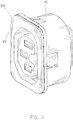
- an apparatus 100 for retaining a plug in a receptacle is shown with retention device 120 inserted within receptacle body 110. It is contemplated that retention device 120 may be inserted within the receptacle body 110 and may retain a plug with a shroud without requiring any modification to the shroud.
- retention device 120 in accordance with various embodiments of the present disclosure is shown. It is contemplated the retention device 120 is operable with at least one prong 124B as shown in FIG. 5 . In alternative embodiments, retention device 120 may include three prongs (124A-124C) and four prongs (124A-124D) as shown in FIG. 4 and FIG. 3 respectively. Additionally, retention device 120 may include two prongs or may include five or more prongs without departing from the scope and intent of the present disclosure. It is further contemplated that the placement of the at least one prong may be adjusted without departing from the scope and intent of the present disclosure. As shown in FIG.
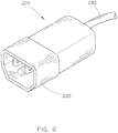
- prongs 124A-124D may be placed to make contact with corners of a shroud 220 of plug 200 as shown in FIG. 6 .
- prongs 124A-124D may be placed to make contact with sides of shroud 220 of plug 200 as shown in FIG. 6 .
- placement of the at least one prong may be placed in alternate locations to make contact with one or more corners and one or more sides of a shroud 220 of plug 200 as shown in FIG. 6 .
- Each prong 124A-124D includes at least one barb 128 and a ridge 130.
- Barb 128 may refer to a projection extending from the prong which is configured to contact a shroud of a plug. It is contemplated that barb 128 may be formed of metal, such as stainless steel, and may project from the prong which may be formed of plastic. It is contemplated that barb 128 may project from the prong at a desired angle in order to enhance the retention of the plug. As shown in FIG. 3 , in one embodiment, each barb extends from each prong at an angle, ⁇ , of about 120-150 degrees from the prong as the prong extends from the face portion 122 of the retention device 120. The desired angle of about 120-150 degrees from the prong as the prong extends from the face portion 122 of the retention device 120 may apply to one or more barbs of one or more prongs of the retention device 120.
- Plug 200 may include a male electrical fitting for making an electrical connection with a corresponding female fitting, such as receptacle 114. It is contemplated that plug 200 may be electrically coupled with cable 230. Plug 200 includes a shroud 220. In an alternative embodiment, plug 200 may include a female electrical fitting for making an electrical connection with a corresponding male fitting, such as an inlet mechanism as shown and described in FIG. 9 and a connector as shown and described in FIG. 10 .
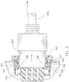
- FIG. 7 depicts a cutaway view of the apparatus for retaining a plug in a receptacle in a retention position in accordance with an embodiment of the present disclosure.
- FIG. 8 depicts a cutaway view of the apparatus for retaining a plug in a receptacle in a release position in accordance with an embodiment of the present disclosure.
- each prong of a plurality of prongs contact shroud 220.
- Each prong is forced toward the shroud 220 by contact from a second side or exterior side of the prong by tapered wall portion 136 of the receptacle body 110.
- the tapered wall portion 136 puts more force on each prong as the plug is pulled from the receptacle body 120 while still remaining in electrical contact with the receptacle.
- the tapered wall portion 136, or ramp reduces the space in the receptacle body as the plug is removed from the body. This causes more force to be applied to each prong of the retention device and causes each barb of each prong to make contact with the shroud.
- the plug may be jammed between the prongs of the retention device and retained within the receptacle body, also referred as an interference fit or contact fit.
- Receptacle body 110 further includes a ledge 134 configured to prevent removal of retention device 120 from the receptacle body 110 by contacting ridge 130 of each prong of the retention device 120.
- face portion 122 of retention device 120 is forced inward toward the receptacle body 110.
- the jam caused by the prongs of the retention device 120 may be released.
- the space within the receptacle body expands as tapered wall portion 136 of the receptacle body 110 may be tapered toward the interior of the receptacle body 110. When this occurs, there is less force applied to each prong by the tapered wall portion 136 of receptacle body 110. As a result, each barb 128 of each prong of the retention device 120 releases the shroud 220 of the plug 200.
- Inlet mechanism 250 may include a male electrical fitting and may be similar as receptacle 110 but may include the male pins.
- Retention device 120 may operate with inlet mechanism 250 to retain a corresponding female electrical fitting such as connector 260 as shown in FIG. 10 . It is contemplated that a barb of at least one prong of retention device 120 may contact and retain a shroud of connector 260.
- retention device 120 and inlet mechanism 250 may include a retention position and release position as described and shown in FIG. 7 and FIG. 8 with respect to a receptacle body 110.
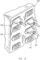
- Power strip 300 including an apparatus for retaining a plug in a receptacle in accordance with an embodiment of the present disclosure is shown.
- Power strip 300 may include a plurality of receptacles 114 which supply power to a plurality of electronic devices. It is contemplated that multiple apparatuses 100 for retaining a plug may be employed in a power strip 300 to prevent unintended disconnection of a plug from a receptacle. It is contemplated that face portion of retention device 120 may include one or more tabs 310. One or more tabs 310 may allow easier finger access to the retention device to allow the retention device to be forced toward the receptacle body to allow removal of a plug.
- a power strip 320 may include an apparatus 100 for retaining a plug in a receptacle and an apparatus 305 for retaining a connector in an inlet mechanism in accordance with an embodiment of the present disclosure is shown. It is contemplated that multiple apparatuses 100, 305 may be employed in a power strip 320 to prevent unintended disconnection of a plug or connector. It is contemplated that face portion of retention device 120 may include one or more tabs 310. One or more tabs 310 may allow easier finger access to the retention device to allow the retention device to be forced toward the receptacle body to allow removal of a plug.
- apparatus 100, 305 may provide a number of advantages over locking receptacles known to the conventional art.
- Conventional locking receptacles may include specialized receptacles or specialized plugs.
- Specialized receptacles and specialized plugs create additional costs and reduce the flexibility to change power cords in a large scale electrical power distribution system, such as power strips employed in a data center providing power to multiple data servers.
- apparatus 100, 305 may be operable with power cords supplied by the manufacturers of electronic equipment, such as data servers.
- apparatus 100, 305 may be operable with IEC 60320 couplers, referring to a list of standards from the International Electrotechnical Commission specifying non-locking appliance couplers and interconnection couplers for the connection of power supply cords to electrical appliances up to 250 Volts, including C13, C15, C19 and C21 receptacles. Additionally, it is contemplated that apparatus 100 may be operable with any type of plug that includes a shroud that may cover at least a portion of the pins of the plug. Also, the apparatus 305 may be operable with a female coupler with any type of shroud.
- An additional advantage of the apparatus 100, 305 may include the ability to employ labels and different colors. By adding an identifier such as color or a label to the face portion 122 of the retention device 120, particular receptacles may be more easily identified and separated, particularly when implemented with a power strip 300, 320 as depicted in FIG. 11 and FIG. 12 .
Landscapes
- Details Of Connecting Devices For Male And Female Coupling (AREA)
Claims (14)
- Appareil (100;305) pour retenir une prise mâle (200) à l'intérieur d'une prise femelle pour une source d'alimentation en courant alternatif AC, comprenant :un corps de prise femelle (110) ; etun dispositif de retenue qui peut être inséré à l'intérieur du corps de prise femelle (110), le dispositif de retenue incluant une partie de face (122) et au moins une broche (124A ; 124B ; 124C ; 124D) qui s'étend depuis la partie de face (122), chaque broche de l'au moins une broche (124A ; 124B ; 124C ; 124D) incluant au moins une aspérité (128), dans lequel le dispositif de retenue (120) est configuré de manière à ce qu'il retienne une prise mâle (200 ; 260) à l'intérieur dudit corps de prise femelle (110) au moyen d'un contact avec une enveloppe (220) de la prise mâle (200 ; 260) au niveau de l'au moins une aspérité (128) de chaque broche de ladite au moins une broche (124A ; 124B ; 124C ; 124D) du dispositif de retenue (120), chaque broche de ladite au moins une broche (124A ; 124B ; 124C ; 124D) du dispositif de retenue (120) inclut une nervure (130) qui est localisée sur un côté opposé de l'au moins une aspérité (128), une paroi intérieure du corps de prise femelle inclut un épaulement (134) qui est configuré de manière à ce qu'il entre en contact avec la nervure de chaque broche et de manière à ce qu'il empêche l'enlèvement du dispositif de retenue (120) hors du corps de prise femelle (110) ;caractérisé en ce que :la paroi intérieure inclut une partie de paroi évasée formant cône (136) ; etdans lequel en utilisation, l'au moins une broche (124A ; 124B ; 124C ; 124D) est forcée en direction de l'enveloppe (220) au moyen de la réalisation d'un contact depuis un second côté ou côté extérieur de la broche par la partie de paroi évasée formant cône (136) du corps de prise femelle (110), de telle sorte que la prise mâle forme un ajustement avec serrage avec la/les broche(s) du dispositif de retenue et soit retenue à l'intérieur du corps de prise femelle ;et en ce que, lorsque la prise mâle (200) doit être enlevée hors de l'appareil permettant de retenir la prise mâle, la partie de face (122) du dispositif de retenue (120) est forcée vers l'intérieur en direction du corps de prise femelle (110).
- Appareil (100 ; 305) tel que revendiqué selon la revendication 1, dans lequel le corps de prise femelle (110) inclut une prise femelle (114 ; 250).
- Appareil (100 ; 305) tel que revendiqué selon la revendication 2, dans lequel ladite prise femelle (114 ; 250) inclut un raccord électrique femelle.
- Appareil (100 ; 305) tel que revendiqué selon la revendication 3, dans lequel ladite prise mâle (200 ; 260) inclut un raccord électrique mâle.
- Appareil (100 ; 305) tel que revendiqué selon la revendication 2, dans lequel ladite prise femelle (114 ; 250) inclut un raccord électrique mâle.
- Appareil (100 ; 305) tel que revendiqué selon la revendication 5, dans lequel ladite prise mâle (200 ; 260) inclut un raccord électrique femelle.
- Appareil (100 ; 305) tel que revendiqué selon la revendication 1, dans lequel ledit dispositif de retenue (120) inclut au moins quatre broches (124A ; 124B ; 124C ; 124D).
- Appareil (100 ; 305) tel que revendiqué selon la revendication 1, dans lequel chaque aspérité (128) s'étend depuis chaque broche (124A ; 124B ; 124C ; 124D) selon un angle d'environ 120 à 150 degrés depuis la broche lorsque la broche (124A ; 124B ; 124C ; 124D) s'étend depuis la partie de face (122) du dispositif de retenue (120).
- Appareil (100 ; 305) selon l'une quelconque des revendications qui précèdent, dans lequel :le corps de prise femelle (110) comprend une prise femelle (114 ; 250), la prise femelle (114 ; 250) incluant un raccord électrique femelle ; etle dispositif de retenue (120) inclut au moins quatre broches (124A ; 124B ; 124C ; 124D), chaque broche des au moins quatre broches (124A ; 124B ; 124C ; 124D) incluant l'aspérité (128) sur un premier côté de la broche et la nervure (130) sur le second côté de la broche ; et dans lequel :l'aspérité (128) inclut un métal.
- Appareil (100 ; 305) tel que revendiqué selon la revendication 9, dans lequel la partie de face (122) et au moins quatre broches (124A ; 124B ; 124C ; 124D) du dispositif de retenue (120) incluent une matière plastique.
- Appareil (305) selon la revendication 9, dans lequel la prise mâle est un connecteur (260) et la prise femelle est un organe d'entrée (250) qui inclut un raccord électrique mâle.
- Appareil (100 ; 305) selon la revendication 1, dans lequel :le corps de prise femelle comprend une prise femelle (114 ; 250), la prise femelle incluant un raccord électrique femelle ; etle dispositif de retenue (120) inclut au moins quatre broches (124A ; 124B ; 124C ; 124D), chaque broche des au moins quatre broches incluant l'aspérité (128) sur un premier côté de la broche et la nervure (130) sur le second côté de la broche.
- Appareil (100 ; 305) selon la revendication 1, dans lequel :le corps de prise femelle (110) comprend une prise femelle (114 ; 250), la prise femelle incluant un raccord électrique femelle ; etle dispositif de retenue (120) inclut au moins quatre broches (124A ; 124B ; 124C ; 124D), chaque broche des au moins quatre broches (124A ; 124B ; 124C ; 124D) incluant l'aspérité (128) sur un premier côté de la broche et une nervure (130) sur le second côté de la broche.
- Appareil (100 ; 305) selon la revendication 1, dans lequel :le corps de prise femelle (110) comprend une prise femelle (114 ; 250), la prise femelle (114 ; 250) incluant un raccord électrique femelle ; etle dispositif de retenue (120) inclut au moins quatre broches (124A ; 124B ; 124C ; 124D), chaque broche des au moins quatre broches (124A ; 124B ; 124C ; 124D) incluant l'aspérité (128) sur un premier côté de la broche et la nervure (130) sur le second côté de la broche.
Applications Claiming Priority (2)
| Application Number | Priority Date | Filing Date | Title |
|---|---|---|---|
| US201361877105P | 2013-09-12 | 2013-09-12 | |
| PCT/US2014/055470 WO2015038945A1 (fr) | 2013-09-12 | 2014-09-12 | Appareil permettant de retenir une prise mâle dans un connecteur femelle |
Publications (3)
| Publication Number | Publication Date |
|---|---|
| EP3044839A1 EP3044839A1 (fr) | 2016-07-20 |
| EP3044839A4 EP3044839A4 (fr) | 2017-03-29 |
| EP3044839B1 true EP3044839B1 (fr) | 2019-07-10 |
Family
ID=56116147
Family Applications (1)
| Application Number | Title | Priority Date | Filing Date |
|---|---|---|---|
| EP14843638.9A Active EP3044839B1 (fr) | 2013-09-12 | 2014-09-12 | Appareil permettant de retenir une prise mâle dans un connecteur femelle |
Country Status (1)
| Country | Link |
|---|---|
| EP (1) | EP3044839B1 (fr) |
Family Cites Families (4)
| Publication number | Priority date | Publication date | Assignee | Title |
|---|---|---|---|---|
| IT1243882B (it) * | 1990-10-31 | 1994-06-28 | C M S R L | Dispositivo per il collegamento di una spina ad una presa di connettori coassiali |
| US5192219A (en) * | 1991-09-17 | 1993-03-09 | Engineered Transitions Co., Inc. | Vibration resistant locking coupling |
| DE10324794B3 (de) * | 2003-05-31 | 2004-12-09 | Woodhead Connectivity Gmbh | Elektrische Steckverbindung |
| TWM428560U (en) * | 2011-12-06 | 2012-05-01 | Chun Nien Plastic Led | Locking socket |
-
2014
- 2014-09-12 EP EP14843638.9A patent/EP3044839B1/fr active Active
Non-Patent Citations (1)
| Title |
|---|
| None * |
Also Published As
| Publication number | Publication date |
|---|---|
| EP3044839A1 (fr) | 2016-07-20 |
| EP3044839A4 (fr) | 2017-03-29 |
Similar Documents
| Publication | Publication Date | Title |
|---|---|---|
| CA2922762C (fr) | Appareil permettant de retenir une prise male dans un connecteur femelle | |
| CN109792119B (zh) | 用于将插头保持在插座中的设备 | |
| US9531126B2 (en) | Electrical receptacle with locking feature | |
| US9692178B2 (en) | Apparatus for retaining a plug in a receptacle | |
| CN111226354A (zh) | 用于经由单个插座为多种类型的插头提供电力的设备 | |
| US9478908B2 (en) | Electrical connector | |
| EP3596742B1 (fr) | Ensemble adaptateur pour transfert sans contact d'énergie électrique | |
| CN203466368U (zh) | 高压连接器 | |
| US11552429B2 (en) | Power plug retention clip | |
| CN104348024B (zh) | 高压连接器 | |
| EP3044839B1 (fr) | Appareil permettant de retenir une prise mâle dans un connecteur femelle | |
| US20170331213A1 (en) | Connector | |
| US7465174B1 (en) | Coupling for connecting and disconnecting a plug and a socket | |
| CN205509188U (zh) | 新型包胶式转接器 | |
| WO2017058200A1 (fr) | Ensemble de retenue de cordon d'alimentation | |
| CA3035249C (fr) | Appareil permettant de retenir une prise male dans un connecteur femelle | |
| CN206313218U (zh) | 一种带防误插插头的连接器结构 | |
| CN202856065U (zh) | 易脱电源连接器组合构造 | |
| CN116706603A (zh) | Usb高拔出力连接器 | |
| KR20110008860U (ko) | 고리를 구비하는 전기 플러그 |
Legal Events
| Date | Code | Title | Description |
|---|---|---|---|
| PUAI | Public reference made under article 153(3) epc to a published international application that has entered the european phase |
Free format text: ORIGINAL CODE: 0009012 |
|
| 17P | Request for examination filed |
Effective date: 20160303 |
|
| AK | Designated contracting states |
Kind code of ref document: A1 Designated state(s): AL AT BE BG CH CY CZ DE DK EE ES FI FR GB GR HR HU IE IS IT LI LT LU LV MC MK MT NL NO PL PT RO RS SE SI SK SM TR |
|
| AX | Request for extension of the european patent |
Extension state: BA ME |
|
| DAX | Request for extension of the european patent (deleted) | ||
| A4 | Supplementary search report drawn up and despatched |
Effective date: 20170224 |
|
| RIC1 | Information provided on ipc code assigned before grant |
Ipc: H01R 103/00 20060101ALI20170220BHEP Ipc: H01R 13/434 20060101ALI20170220BHEP Ipc: H01R 24/78 20110101ALI20170220BHEP Ipc: H01R 13/639 20060101ALI20170220BHEP Ipc: H01R 13/428 20060101AFI20170220BHEP |
|
| STAA | Information on the status of an ep patent application or granted ep patent |
Free format text: STATUS: EXAMINATION IS IN PROGRESS |
|
| 17Q | First examination report despatched |
Effective date: 20180104 |
|
| RAP1 | Party data changed (applicant data changed or rights of an application transferred) |
Owner name: LIEBERT CORPORATION |
|
| RAP1 | Party data changed (applicant data changed or rights of an application transferred) |
Owner name: VERTIV CORPORATION |
|
| GRAP | Despatch of communication of intention to grant a patent |
Free format text: ORIGINAL CODE: EPIDOSNIGR1 |
|
| STAA | Information on the status of an ep patent application or granted ep patent |
Free format text: STATUS: GRANT OF PATENT IS INTENDED |
|
| INTG | Intention to grant announced |
Effective date: 20190305 |
|
| GRAS | Grant fee paid |
Free format text: ORIGINAL CODE: EPIDOSNIGR3 |
|
| GRAA | (expected) grant |
Free format text: ORIGINAL CODE: 0009210 |
|
| STAA | Information on the status of an ep patent application or granted ep patent |
Free format text: STATUS: THE PATENT HAS BEEN GRANTED |
|
| AK | Designated contracting states |
Kind code of ref document: B1 Designated state(s): AL AT BE BG CH CY CZ DE DK EE ES FI FR GB GR HR HU IE IS IT LI LT LU LV MC MK MT NL NO PL PT RO RS SE SI SK SM TR |
|
| REG | Reference to a national code |
Ref country code: GB Ref legal event code: FG4D |
|
| REG | Reference to a national code |
Ref country code: CH Ref legal event code: EP Ref country code: AT Ref legal event code: REF Ref document number: 1154499 Country of ref document: AT Kind code of ref document: T Effective date: 20190715 |
|
| REG | Reference to a national code |
Ref country code: IE Ref legal event code: FG4D |
|
| REG | Reference to a national code |
Ref country code: DE Ref legal event code: R096 Ref document number: 602014049947 Country of ref document: DE |
|
| REG | Reference to a national code |
Ref country code: NL Ref legal event code: MP Effective date: 20190710 |
|
| REG | Reference to a national code |
Ref country code: LT Ref legal event code: MG4D |
|
| REG | Reference to a national code |
Ref country code: AT Ref legal event code: MK05 Ref document number: 1154499 Country of ref document: AT Kind code of ref document: T Effective date: 20190710 |
|
| PG25 | Lapsed in a contracting state [announced via postgrant information from national office to epo] |
Ref country code: AT Free format text: LAPSE BECAUSE OF FAILURE TO SUBMIT A TRANSLATION OF THE DESCRIPTION OR TO PAY THE FEE WITHIN THE PRESCRIBED TIME-LIMIT Effective date: 20190710 Ref country code: NL Free format text: LAPSE BECAUSE OF FAILURE TO SUBMIT A TRANSLATION OF THE DESCRIPTION OR TO PAY THE FEE WITHIN THE PRESCRIBED TIME-LIMIT Effective date: 20190710 Ref country code: BG Free format text: LAPSE BECAUSE OF FAILURE TO SUBMIT A TRANSLATION OF THE DESCRIPTION OR TO PAY THE FEE WITHIN THE PRESCRIBED TIME-LIMIT Effective date: 20191010 Ref country code: SE Free format text: LAPSE BECAUSE OF FAILURE TO SUBMIT A TRANSLATION OF THE DESCRIPTION OR TO PAY THE FEE WITHIN THE PRESCRIBED TIME-LIMIT Effective date: 20190710 Ref country code: LT Free format text: LAPSE BECAUSE OF FAILURE TO SUBMIT A TRANSLATION OF THE DESCRIPTION OR TO PAY THE FEE WITHIN THE PRESCRIBED TIME-LIMIT Effective date: 20190710 Ref country code: PT Free format text: LAPSE BECAUSE OF FAILURE TO SUBMIT A TRANSLATION OF THE DESCRIPTION OR TO PAY THE FEE WITHIN THE PRESCRIBED TIME-LIMIT Effective date: 20191111 Ref country code: HR Free format text: LAPSE BECAUSE OF FAILURE TO SUBMIT A TRANSLATION OF THE DESCRIPTION OR TO PAY THE FEE WITHIN THE PRESCRIBED TIME-LIMIT Effective date: 20190710 Ref country code: FI Free format text: LAPSE BECAUSE OF FAILURE TO SUBMIT A TRANSLATION OF THE DESCRIPTION OR TO PAY THE FEE WITHIN THE PRESCRIBED TIME-LIMIT Effective date: 20190710 Ref country code: NO Free format text: LAPSE BECAUSE OF FAILURE TO SUBMIT A TRANSLATION OF THE DESCRIPTION OR TO PAY THE FEE WITHIN THE PRESCRIBED TIME-LIMIT Effective date: 20191010 |
|
| PG25 | Lapsed in a contracting state [announced via postgrant information from national office to epo] |
Ref country code: LV Free format text: LAPSE BECAUSE OF FAILURE TO SUBMIT A TRANSLATION OF THE DESCRIPTION OR TO PAY THE FEE WITHIN THE PRESCRIBED TIME-LIMIT Effective date: 20190710 Ref country code: IS Free format text: LAPSE BECAUSE OF FAILURE TO SUBMIT A TRANSLATION OF THE DESCRIPTION OR TO PAY THE FEE WITHIN THE PRESCRIBED TIME-LIMIT Effective date: 20191110 Ref country code: ES Free format text: LAPSE BECAUSE OF FAILURE TO SUBMIT A TRANSLATION OF THE DESCRIPTION OR TO PAY THE FEE WITHIN THE PRESCRIBED TIME-LIMIT Effective date: 20190710 Ref country code: AL Free format text: LAPSE BECAUSE OF FAILURE TO SUBMIT A TRANSLATION OF THE DESCRIPTION OR TO PAY THE FEE WITHIN THE PRESCRIBED TIME-LIMIT Effective date: 20190710 Ref country code: RS Free format text: LAPSE BECAUSE OF FAILURE TO SUBMIT A TRANSLATION OF THE DESCRIPTION OR TO PAY THE FEE WITHIN THE PRESCRIBED TIME-LIMIT Effective date: 20190710 Ref country code: GR Free format text: LAPSE BECAUSE OF FAILURE TO SUBMIT A TRANSLATION OF THE DESCRIPTION OR TO PAY THE FEE WITHIN THE PRESCRIBED TIME-LIMIT Effective date: 20191011 |
|
| PG25 | Lapsed in a contracting state [announced via postgrant information from national office to epo] |
Ref country code: TR Free format text: LAPSE BECAUSE OF FAILURE TO SUBMIT A TRANSLATION OF THE DESCRIPTION OR TO PAY THE FEE WITHIN THE PRESCRIBED TIME-LIMIT Effective date: 20190710 |
|
| PG25 | Lapsed in a contracting state [announced via postgrant information from national office to epo] |
Ref country code: DK Free format text: LAPSE BECAUSE OF FAILURE TO SUBMIT A TRANSLATION OF THE DESCRIPTION OR TO PAY THE FEE WITHIN THE PRESCRIBED TIME-LIMIT Effective date: 20190710 Ref country code: EE Free format text: LAPSE BECAUSE OF FAILURE TO SUBMIT A TRANSLATION OF THE DESCRIPTION OR TO PAY THE FEE WITHIN THE PRESCRIBED TIME-LIMIT Effective date: 20190710 Ref country code: RO Free format text: LAPSE BECAUSE OF FAILURE TO SUBMIT A TRANSLATION OF THE DESCRIPTION OR TO PAY THE FEE WITHIN THE PRESCRIBED TIME-LIMIT Effective date: 20190710 Ref country code: PL Free format text: LAPSE BECAUSE OF FAILURE TO SUBMIT A TRANSLATION OF THE DESCRIPTION OR TO PAY THE FEE WITHIN THE PRESCRIBED TIME-LIMIT Effective date: 20190710 |
|
| PG25 | Lapsed in a contracting state [announced via postgrant information from national office to epo] |
Ref country code: MC Free format text: LAPSE BECAUSE OF FAILURE TO SUBMIT A TRANSLATION OF THE DESCRIPTION OR TO PAY THE FEE WITHIN THE PRESCRIBED TIME-LIMIT Effective date: 20190710 Ref country code: SM Free format text: LAPSE BECAUSE OF FAILURE TO SUBMIT A TRANSLATION OF THE DESCRIPTION OR TO PAY THE FEE WITHIN THE PRESCRIBED TIME-LIMIT Effective date: 20190710 Ref country code: IS Free format text: LAPSE BECAUSE OF FAILURE TO SUBMIT A TRANSLATION OF THE DESCRIPTION OR TO PAY THE FEE WITHIN THE PRESCRIBED TIME-LIMIT Effective date: 20200224 Ref country code: CZ Free format text: LAPSE BECAUSE OF FAILURE TO SUBMIT A TRANSLATION OF THE DESCRIPTION OR TO PAY THE FEE WITHIN THE PRESCRIBED TIME-LIMIT Effective date: 20190710 Ref country code: SK Free format text: LAPSE BECAUSE OF FAILURE TO SUBMIT A TRANSLATION OF THE DESCRIPTION OR TO PAY THE FEE WITHIN THE PRESCRIBED TIME-LIMIT Effective date: 20190710 |
|
| REG | Reference to a national code |
Ref country code: CH Ref legal event code: PL |
|
| REG | Reference to a national code |
Ref country code: DE Ref legal event code: R097 Ref document number: 602014049947 Country of ref document: DE |
|
| PLBE | No opposition filed within time limit |
Free format text: ORIGINAL CODE: 0009261 |
|
| STAA | Information on the status of an ep patent application or granted ep patent |
Free format text: STATUS: NO OPPOSITION FILED WITHIN TIME LIMIT |
|
| PG2D | Information on lapse in contracting state deleted |
Ref country code: IS |
|
| PG25 | Lapsed in a contracting state [announced via postgrant information from national office to epo] |
Ref country code: LU Free format text: LAPSE BECAUSE OF NON-PAYMENT OF DUE FEES Effective date: 20190912 Ref country code: IE Free format text: LAPSE BECAUSE OF NON-PAYMENT OF DUE FEES Effective date: 20190912 Ref country code: LI Free format text: LAPSE BECAUSE OF NON-PAYMENT OF DUE FEES Effective date: 20190930 Ref country code: CH Free format text: LAPSE BECAUSE OF NON-PAYMENT OF DUE FEES Effective date: 20190930 |
|
| REG | Reference to a national code |
Ref country code: BE Ref legal event code: MM Effective date: 20190930 |
|
| 26N | No opposition filed |
Effective date: 20200603 |
|
| PG25 | Lapsed in a contracting state [announced via postgrant information from national office to epo] |
Ref country code: SI Free format text: LAPSE BECAUSE OF FAILURE TO SUBMIT A TRANSLATION OF THE DESCRIPTION OR TO PAY THE FEE WITHIN THE PRESCRIBED TIME-LIMIT Effective date: 20190710 Ref country code: BE Free format text: LAPSE BECAUSE OF NON-PAYMENT OF DUE FEES Effective date: 20190930 |
|
| PG25 | Lapsed in a contracting state [announced via postgrant information from national office to epo] |
Ref country code: CY Free format text: LAPSE BECAUSE OF FAILURE TO SUBMIT A TRANSLATION OF THE DESCRIPTION OR TO PAY THE FEE WITHIN THE PRESCRIBED TIME-LIMIT Effective date: 20190710 |
|
| PG25 | Lapsed in a contracting state [announced via postgrant information from national office to epo] |
Ref country code: HU Free format text: LAPSE BECAUSE OF FAILURE TO SUBMIT A TRANSLATION OF THE DESCRIPTION OR TO PAY THE FEE WITHIN THE PRESCRIBED TIME-LIMIT; INVALID AB INITIO Effective date: 20140912 Ref country code: MT Free format text: LAPSE BECAUSE OF FAILURE TO SUBMIT A TRANSLATION OF THE DESCRIPTION OR TO PAY THE FEE WITHIN THE PRESCRIBED TIME-LIMIT Effective date: 20190710 |
|
| PG25 | Lapsed in a contracting state [announced via postgrant information from national office to epo] |
Ref country code: MK Free format text: LAPSE BECAUSE OF FAILURE TO SUBMIT A TRANSLATION OF THE DESCRIPTION OR TO PAY THE FEE WITHIN THE PRESCRIBED TIME-LIMIT Effective date: 20190710 |
|
| P01 | Opt-out of the competence of the unified patent court (upc) registered |
Effective date: 20230621 |
|
| PGFP | Annual fee paid to national office [announced via postgrant information from national office to epo] |
Ref country code: DE Payment date: 20250929 Year of fee payment: 12 |
|
| PGFP | Annual fee paid to national office [announced via postgrant information from national office to epo] |
Ref country code: IT Payment date: 20250919 Year of fee payment: 12 |
|
| PGFP | Annual fee paid to national office [announced via postgrant information from national office to epo] |
Ref country code: GB Payment date: 20250929 Year of fee payment: 12 |
|
| PGFP | Annual fee paid to national office [announced via postgrant information from national office to epo] |
Ref country code: FR Payment date: 20250925 Year of fee payment: 12 |