EP3044860B1 - Machine électrique - Google Patents
Machine électrique Download PDFInfo
- Publication number
- EP3044860B1 EP3044860B1 EP14759214.1A EP14759214A EP3044860B1 EP 3044860 B1 EP3044860 B1 EP 3044860B1 EP 14759214 A EP14759214 A EP 14759214A EP 3044860 B1 EP3044860 B1 EP 3044860B1
- Authority
- EP
- European Patent Office
- Prior art keywords
- rotor
- stator
- switching
- electric machine
- coil
- Prior art date
- Legal status (The legal status is an assumption and is not a legal conclusion. Google has not performed a legal analysis and makes no representation as to the accuracy of the status listed.)
- Not-in-force
Links
- 238000000034 method Methods 0.000 claims description 9
- 238000004891 communication Methods 0.000 claims description 8
- 230000001360 synchronised effect Effects 0.000 description 28
- 230000006698 induction Effects 0.000 description 16
- 230000002441 reversible effect Effects 0.000 description 16
- 230000008901 benefit Effects 0.000 description 6
- 238000004146 energy storage Methods 0.000 description 4
- 239000002184 metal Substances 0.000 description 4
- 230000007704 transition Effects 0.000 description 3
- 239000004020 conductor Substances 0.000 description 2
- 230000001419 dependent effect Effects 0.000 description 2
- 230000003068 static effect Effects 0.000 description 2
- OKTJSMMVPCPJKN-UHFFFAOYSA-N Carbon Chemical compound [C] OKTJSMMVPCPJKN-UHFFFAOYSA-N 0.000 description 1
- 229910000976 Electrical steel Inorganic materials 0.000 description 1
- 230000003466 anti-cipated effect Effects 0.000 description 1
- 230000000712 assembly Effects 0.000 description 1
- 238000000429 assembly Methods 0.000 description 1
- 239000003990 capacitor Substances 0.000 description 1
- 230000015556 catabolic process Effects 0.000 description 1
- 238000006243 chemical reaction Methods 0.000 description 1
- 229910002804 graphite Inorganic materials 0.000 description 1
- 239000010439 graphite Substances 0.000 description 1
- 230000007257 malfunction Effects 0.000 description 1
- 230000002093 peripheral effect Effects 0.000 description 1
- 239000004065 semiconductor Substances 0.000 description 1
- 238000009987 spinning Methods 0.000 description 1
- 238000004804 winding Methods 0.000 description 1
Images


Classifications
-
- H—ELECTRICITY
- H02—GENERATION; CONVERSION OR DISTRIBUTION OF ELECTRIC POWER
- H02K—DYNAMO-ELECTRIC MACHINES
- H02K19/00—Synchronous motors or generators
- H02K19/02—Synchronous motors
- H02K19/10—Synchronous motors for multi-phase current
- H02K19/12—Synchronous motors for multi-phase current characterised by the arrangement of exciting windings, e.g. for self-excitation, compounding or pole-changing
-
- H—ELECTRICITY
- H02—GENERATION; CONVERSION OR DISTRIBUTION OF ELECTRIC POWER
- H02K—DYNAMO-ELECTRIC MACHINES
- H02K17/00—Asynchronous induction motors; Asynchronous induction generators
- H02K17/02—Asynchronous induction motors
- H02K17/22—Asynchronous induction motors having rotors with windings connected to slip-rings
-
- H—ELECTRICITY
- H02—GENERATION; CONVERSION OR DISTRIBUTION OF ELECTRIC POWER
- H02K—DYNAMO-ELECTRIC MACHINES
- H02K17/00—Asynchronous induction motors; Asynchronous induction generators
- H02K17/02—Asynchronous induction motors
- H02K17/26—Asynchronous induction motors having rotors or stators designed to permit synchronous operation
-
- H—ELECTRICITY
- H02—GENERATION; CONVERSION OR DISTRIBUTION OF ELECTRIC POWER
- H02K—DYNAMO-ELECTRIC MACHINES
- H02K19/00—Synchronous motors or generators
- H02K19/16—Synchronous generators
- H02K19/26—Synchronous generators characterised by the arrangement of exciting windings
-
- H—ELECTRICITY
- H02—GENERATION; CONVERSION OR DISTRIBUTION OF ELECTRIC POWER
- H02K—DYNAMO-ELECTRIC MACHINES
- H02K19/00—Synchronous motors or generators
- H02K19/16—Synchronous generators
- H02K19/26—Synchronous generators characterised by the arrangement of exciting windings
- H02K19/32—Synchronous generators characterised by the arrangement of exciting windings for pole-changing
-
- H—ELECTRICITY
- H02—GENERATION; CONVERSION OR DISTRIBUTION OF ELECTRIC POWER
- H02K—DYNAMO-ELECTRIC MACHINES
- H02K3/00—Details of windings
- H02K3/04—Windings characterised by the conductor shape, form or construction, e.g. with bar conductors
- H02K3/28—Layout of windings or of connections between windings
-
- H—ELECTRICITY
- H02—GENERATION; CONVERSION OR DISTRIBUTION OF ELECTRIC POWER
- H02K—DYNAMO-ELECTRIC MACHINES
- H02K99/00—Subject matter not provided for in other groups of this subclass
-
- H—ELECTRICITY
- H02—GENERATION; CONVERSION OR DISTRIBUTION OF ELECTRIC POWER
- H02K—DYNAMO-ELECTRIC MACHINES
- H02K2213/00—Specific aspects, not otherwise provided for and not covered by codes H02K2201/00 - H02K2211/00
- H02K2213/06—Machines characterised by the presence of fail safe, back up, redundant or other similar emergency arrangements
-
- H—ELECTRICITY
- H02—GENERATION; CONVERSION OR DISTRIBUTION OF ELECTRIC POWER
- H02K—DYNAMO-ELECTRIC MACHINES
- H02K2213/00—Specific aspects, not otherwise provided for and not covered by codes H02K2201/00 - H02K2211/00
- H02K2213/09—Machines characterised by the presence of elements which are subject to variation, e.g. adjustable bearings, reconfigurable windings, variable pitch ventilators
Definitions
- the rotor-switching device comprises a rotor-control-unit and at least one switch which is adapted to electrically connect rotor-coils and/or to provide or disconnect an electric connection to a power source.
- the rotor-control-unit is adapted to activate preselected electrical switches at a predefined moment of time so that for a given rotor coil one of the following events occur:
- the rotor comprises means to provide or conduct electric power, in particular a slip ring or a rotary transformer.
- a slip ring is an electrical connector designed to carry current or signals from a stationary wire into a rotating device. Typically, it consists of a stationary graphite or metal contact (brush) which rubs on the outside diameter of a rotating metal ring. As the metal ring turns, the electrical current or signal is conducted through the stationary brush to the metal ring making the connection. Additional ring/brush assemblies are stacked along the rotating axis if more than one electrical circuit is needed. Either the brushes or the rings are stationary and the other component rotates.
- a rotary (rotatory) transformer is a specialized transformer used to couple electrical signals between two parts that rotate in relation to each other.
- the electric machine comprises a stator-switching-device which comprises a stator-control-unit, wherein the stator-switching-device comprises at least one switch which is adapted to electrically connect stator-coils and/or to provide or disconnect an electric connection to the power source.
- these switches are of the same type and design as the switches of the rotor-switching-device.
- the stator-switching-device is adapted to activate preselected electrical switches at a predefined moment of time so that for a given stator coil one of the following events occur:
- the magnetic field created by the rotor is not static, but it is rotating relative to the rotor itself and electric energy is either "pumped" to the rotor or taken out of the rotor depending on current operation mode.
- the rotor may create a variable pole magnetic field which rotates relative to the rotor itself.
- the rotor as well as the stator can generate rotating magnetic fields (using e.g. three-phase AC).
- the stator-switching-device is adapted to vary a number of stator-pole-pairs by electrically connecting appropriate stator-coils, wherein the rotor-switching-device is adapted to vary a number of rotor-pole-pairs by electrically connecting appropriate rotor-coils.
- rotor slots there are preferably four rotor slots and six stator slots.
- the number of rotor coils is preferably four and the number of stator coils is preferably six.
- Each coil occupies two adjacent slots, thus a stator coil annular pitch is 60° and a rotor coil angular pitch is 90°.
- the rotor is expediently supplied with DC through two slip rings.
- the electric machine can be operated as synchronous machine and as induction machine.
- induction operation mode the rotor switching device switches rotor-coils in short and not to any of the AC phases or the DC power source.
- the rotating magnetic field created by the stator will induce electric currents in the rotor-coils which is the principle behind induction motors.
- the rotor-switching-device is capable of changing the magnetic pole number of the rotor. It is adapted to connect rotor-coils in short thus operating the electric machine in induction mode. This is useful when starting the electric machine and also during transition between two synchronous speeds.
- Electric power is delivered to the rotor via e. g. two slip rings or brushless via rotary transformers and rectifiers.
- the electric machine will operate as single fed induction machine. If the frequency of the multiphase AC source supplied to the rotor drops to zero then the electric machine will operate as single fed synchronous machine.
- Further benefits can bring the ability to connect sensors to the rotor-switching-device to monitor key characteristics of the rotor during operation. For instance temperature, rotor coil electric currents and other important readings can be monitored inside the rotor and information passed to the stator-switching-device via the information channel or the communication connection, respectively, between the two switching devices, This way malfunctions can be anticipated before a major accident occurs. It is also possible a set of gyroscopic sensors inside the rotor to determine exact position of the rotor at a certain moment of time. This may eliminate the need of complicated other sensors mounted outside the rotor with the same function.
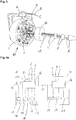
- Fig. 2a shows a communication connection 50 between the rotor-switching-device 64 and the stator-switching device 44.
- a rotor-control-unit 66 is connected to a stator-control-unit 46.
- the rotor-switching-device 64 also comprises a sensor 92 and a rotor energy storage unit 90.
- Fig. 3 basically shows the same concept as Figure 1 .
- a rotor 60 is provided with alternating current.
- This type of machine is named doubly fed machine.
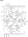
- Figure 4b shows the design in detail.
Landscapes
- Engineering & Computer Science (AREA)
- Power Engineering (AREA)
- Synchronous Machinery (AREA)
- Induction Machinery (AREA)
- Iron Core Of Rotating Electric Machines (AREA)
- Connection Of Motors, Electrical Generators, Mechanical Devices, And The Like (AREA)
Claims (10)
- Machine électrique (20) comprenant un stator (40), un dispositif de commutation de stator (44) et un rotor (60),
dans laquelle le rotor (60) est adapté à tourner sélectivement par rapport au stator (40), et
dans laquelle le rotor (60) comprend un dispositif de commutation de rotor (64) qui est agencé au niveau du rotor (60),
dans laquelle le dispositif de commutation de rotor (64) comprend au moins un commutateur (I) qui est adapté à connecter électriquement des bobinages de rotor (r, r2, r3, ...), et
dans laquelle le dispositif de commutation de stator (44) comprend au moins un commutateur (I) qui est adapté à connecter électriquement des bobinages de stator (s, s2, s3, ...),
caractérisé en ce que
le dispositif de commutation de stator (44) est adapté à faire varier un nombre de paires de pôles de stator, et en ce que
le dispositif de commutation de rotor (64) est adapté à faire varier un nombre de paires de pôles de rotor. - Machine électrique (20) selon la revendication 1,
dans laquelle ledit au moins un commutateur (I) du dispositif de commutation de rotor (64) est adapté à établir ou à déconnecter une connexion électrique vers une source de puissance. - Machine électrique (20) selon les revendications 1 ou 2,
dans laquelle le rotor (60) comprend un moyen (62) pour fournir ou pour conduire une puissance électrique, en particulier une bague glissante ou un transformateur rotatif. - Machine électrique (20) selon l'une quelconque des revendications précédentes,
dans laquelle le dispositif de commutation de rotor (64) comprend au moins un convertisseur électrique, comme un convertisseur continu/continu, un convertisseur continu/alternatif, et un convertisseur alternatif/alternatif et/ou un convertisseur alternatif/continu. - Machine électrique (20) selon l'une quelconque des revendications précédentes,
dans laquelle ledit au moins un commutateur (I) du dispositif de commutation de stator (44) est adapté à établir une connexion électrique vers une source de puissance. - Machine électrique (20) selon l'une quelconque des revendications 4 et 5, dans laquelle le dispositif de commutation de rotor (64) et le dispositif de commutation de stator (44) sont connectés par une connexion de communication (50).
- Machine électrique (20) selon l'une quelconque des revendications 2 à 6, dans laquelle la source de puissance est une source de puissance en courant alternatif ou en courant continu (84, 84').
- Machine électrique (20) selon l'une quelconque des revendications précédentes,
dans laquelle le rotor (60) comprend au moins un capteur (92) qui est adapté à fournir une information concernant un état du rotor (60), comme une position du rotor, une température interne au rotor, les courants électriques dans les bobinages de rotor, les conditions d'alimentation de puissance, les niveaux de vibration, etc. - Machine électrique (20) selon l'une quelconque des revendications précédentes,
dans laquelle le dispositif de commutation de rotor (64) comprend une unité de stockage d'énergie de rotor (90). - Procédé pour le fonctionnement d'une machine électrique (20), comprenant un stator (40) et un rotor (60),
dans laquelle le rotor (60) est adapté à tourner par rapport au stator (40), et dans laquelle le rotor (60) comprend un dispositif de commutation de rotor (64) qui est agencé au niveau du rotor (60),
comprenant les étapes consistant à :- alimenter le stator (40) avec du courant alternatif en utilisant un dispositif de commutation de stator (44) ;- alimenter le rotor (60) avec courant alternatif ou continu, ou mettre en court-circuit le rotor (60), en utilisant le dispositif de commutation de rotor (64) ;- coordonner le dispositif de commutation de stator (44) et le dispositif de commutation de rotor (64) de sorte qu'un nombre de paires de pôles de rotor et un nombre de paires de pôles de stator sont les mêmes.
Priority Applications (1)
| Application Number | Priority Date | Filing Date | Title |
|---|---|---|---|
| EP14759214.1A EP3044860B1 (fr) | 2013-11-28 | 2014-09-08 | Machine électrique |
Applications Claiming Priority (3)
| Application Number | Priority Date | Filing Date | Title |
|---|---|---|---|
| EP13194936.4A EP2879280A1 (fr) | 2013-11-28 | 2013-11-28 | Machine électrique |
| EP14759214.1A EP3044860B1 (fr) | 2013-11-28 | 2014-09-08 | Machine électrique |
| PCT/EP2014/069035 WO2015078603A1 (fr) | 2013-11-28 | 2014-09-08 | Machine électrique |
Publications (2)
| Publication Number | Publication Date |
|---|---|
| EP3044860A1 EP3044860A1 (fr) | 2016-07-20 |
| EP3044860B1 true EP3044860B1 (fr) | 2017-05-31 |
Family
ID=49674210
Family Applications (2)
| Application Number | Title | Priority Date | Filing Date |
|---|---|---|---|
| EP13194936.4A Withdrawn EP2879280A1 (fr) | 2013-11-28 | 2013-11-28 | Machine électrique |
| EP14759214.1A Not-in-force EP3044860B1 (fr) | 2013-11-28 | 2014-09-08 | Machine électrique |
Family Applications Before (1)
| Application Number | Title | Priority Date | Filing Date |
|---|---|---|---|
| EP13194936.4A Withdrawn EP2879280A1 (fr) | 2013-11-28 | 2013-11-28 | Machine électrique |
Country Status (5)
| Country | Link |
|---|---|
| EP (2) | EP2879280A1 (fr) |
| JP (1) | JP2016510971A (fr) |
| CN (1) | CN104813569A (fr) |
| BR (1) | BR112016011885A2 (fr) |
| WO (1) | WO2015078603A1 (fr) |
Families Citing this family (9)
| Publication number | Priority date | Publication date | Assignee | Title |
|---|---|---|---|---|
| EP3211788A1 (fr) * | 2016-02-23 | 2017-08-30 | NRG Tech Ltd. | Moteur électrique à induction à double alimentation |
| CN106208895A (zh) * | 2016-08-05 | 2016-12-07 | 曹兵 | 交流电机的直流驱动方法、系统及利用该系统的同步电机 |
| DE102019212055A1 (de) * | 2019-08-12 | 2020-08-06 | Magna powertrain gmbh & co kg | Elektrisches Antriebssystem mit einer fremderregten Synchronmaschine |
| JP2023524315A (ja) * | 2020-05-08 | 2023-06-09 | グリフィス ユニバーシティー | 高周波トランスおよびその用途 |
| US11499524B2 (en) | 2021-02-17 | 2022-11-15 | General Electric Company | System and method for controlling low-speed operations of a wind turbine |
| EP4108641A1 (fr) | 2021-06-24 | 2022-12-28 | Heraeus Quarzglas GmbH & Co. KG | Corps moulé en verre de quartz opaque, ainsi que son procédé de fabrication |
| EP4280424A1 (fr) | 2022-05-18 | 2023-11-22 | GE Energy Power Conversion Technology Ltd | Machine électrique synchrone et bateau comprenant une telle machine |
| DE102023201203A1 (de) * | 2023-02-14 | 2024-08-14 | Zf Friedrichshafen Ag | Synchronmaschine und Fahrzeug |
| US20250119071A1 (en) * | 2023-10-04 | 2025-04-10 | C-Motive Technologies, Inc. | Ac-driven electrostatic machine |
Family Cites Families (22)
| Publication number | Priority date | Publication date | Assignee | Title |
|---|---|---|---|---|
| BE372648A (fr) * | ||||
| US1770871A (en) * | 1929-08-12 | 1930-07-15 | Gen Electr Company | Double-speed, synchronous, dynamo-electric machine |
| DE934180C (de) * | 1940-02-14 | 1955-10-13 | Siemens Ag | Elektrische Maschine mit verteilter Gleichstromerregerwicklung |
| CH121140A (de) * | 1940-11-12 | 1927-06-16 | Bbc Brown Boveri & Cie | Einrichtung zum selektiven Erkennen eines Erdschluss habenden Leitungsabschnittes einer verschiedene Zentralen verbindenden Hochspannungsleitung. |
| US2726361A (en) * | 1953-04-08 | 1955-12-06 | Allis Chalmers Mfg Co | Dynamoelectric machine utilizing a component of the field flux wave |
| US2782352A (en) * | 1953-05-29 | 1957-02-19 | Hartford Nat Bank & Trust Co | Alternating-current motor |
| DE1276806B (de) * | 1962-01-29 | 1968-09-05 | Licentia Gmbh | Synchronisierte Asynchronmaschine, deren Sekundaerwicklung in zwei Gruppen unterteilt ist |
| US4039909A (en) * | 1975-02-10 | 1977-08-02 | Massachusetts Institute Of Technology | Variable speed electronic motor and the like |
| JPS59110357A (ja) * | 1982-12-11 | 1984-06-26 | Tadashi Onishi | 交流二同期速度発電機 |
| IT1191814B (it) * | 1986-06-27 | 1988-03-23 | Brown Boveri Tecnomasio Ital | Circuito di commutazione del numero di poli su rotore di macchine sincrone con impiego di diodi rotanti |
| US4982147A (en) * | 1989-01-30 | 1991-01-01 | State Of Oregon Acting By And Through The State Board Of Higher Education On Behalf Of Oregon State University | Power factor motor control system |
| JPH04331447A (ja) * | 1991-04-26 | 1992-11-19 | Toyota Motor Corp | 永久磁石電動機 |
| JPH10210794A (ja) * | 1997-01-24 | 1998-08-07 | Mitsubishi Heavy Ind Ltd | エンジン発電装置 |
| EP1012952A1 (fr) * | 1997-01-29 | 2000-06-28 | Dieter W. Blum | Machines dynamoelectriques, et systeme de commande et d'exploitation pour lesdites machines |
| WO1999014847A1 (fr) * | 1997-09-18 | 1999-03-25 | Mildice James W | Systeme machine universelle a vitesse variable |
| JP4226694B2 (ja) * | 1998-08-27 | 2009-02-18 | 電源開発株式会社 | 多速度発電電動機 |
| US8319481B2 (en) * | 2006-12-26 | 2012-11-27 | Hamilton Sundstrand Corporation | Pole shifting generator |
| US7969122B2 (en) * | 2007-11-14 | 2011-06-28 | Hamilton Sundstrand Corporation | Pole count changing generator |
| JP5206130B2 (ja) * | 2008-06-05 | 2013-06-12 | 三菱電機株式会社 | コイル界磁式同期モーター回生システムおよびその制御方法 |
| JP2010136523A (ja) * | 2008-12-04 | 2010-06-17 | Toyota Central R&D Labs Inc | 回転電機の駆動制御装置 |
| JP5827026B2 (ja) * | 2011-04-07 | 2015-12-02 | トヨタ自動車株式会社 | 回転電機及び回転電機駆動システム |
| US8803384B2 (en) * | 2011-05-10 | 2014-08-12 | The Boeing Company | Stators with reconfigurable coil paths |
-
2013
- 2013-11-28 EP EP13194936.4A patent/EP2879280A1/fr not_active Withdrawn
-
2014
- 2014-09-08 CN CN201480001030.2A patent/CN104813569A/zh active Pending
- 2014-09-08 EP EP14759214.1A patent/EP3044860B1/fr not_active Not-in-force
- 2014-09-08 JP JP2015560729A patent/JP2016510971A/ja active Pending
- 2014-09-08 BR BR112016011885A patent/BR112016011885A2/pt not_active IP Right Cessation
- 2014-09-08 WO PCT/EP2014/069035 patent/WO2015078603A1/fr not_active Ceased
Also Published As
| Publication number | Publication date |
|---|---|
| WO2015078603A1 (fr) | 2015-06-04 |
| EP2879280A1 (fr) | 2015-06-03 |
| JP2016510971A (ja) | 2016-04-11 |
| CN104813569A (zh) | 2015-07-29 |
| EP3044860A1 (fr) | 2016-07-20 |
| BR112016011885A2 (pt) | 2017-08-08 |
Similar Documents
| Publication | Publication Date | Title |
|---|---|---|
| EP3044860B1 (fr) | Machine électrique | |
| US20150364978A1 (en) | Electric Machine | |
| EP3151396B1 (fr) | Appareil de commande pour machine électrique rotative et système | |
| US11223311B2 (en) | Rotary electric machine and rotary electric machine system | |
| US6977454B2 (en) | Hybrid-secondary uncluttered permanent magnet machine and method | |
| CN105634225B (zh) | 直流无刷电机及使用其的电动助力转向系统 | |
| EP0648006B1 (fr) | Stator pour dispositif electrique utilisant du courant alternatif | |
| US20150008777A1 (en) | Synchronous electric machine | |
| JP5301905B2 (ja) | 複数相回転電機駆動装置、複数相発電機用コンバータ、複数相回転電機、及び回転電機駆動システム | |
| CN110365133A (zh) | 永磁交流发电机 | |
| RU2390086C1 (ru) | Бесконтактная редукторная электрическая машина с комбинированным возбуждением | |
| EP0084717B1 (fr) | Machine électrique | |
| KR102053719B1 (ko) | 복합 발전기 | |
| EP3506490A1 (fr) | Dispositif de génération d'énergie synchrone sans balais | |
| RU2392724C1 (ru) | Однофазный электрический генератор | |
| RU2586895C1 (ru) | Способ электропитания | |
| RU2414039C1 (ru) | Модульная синхронная электрическая машина | |
| US20070222408A1 (en) | Simplified solid state electric motor drive technique | |
| CN110868032B (zh) | 多转子电机 | |
| US20040164701A1 (en) | Electrodynamic machines and components therefor and methods of making and using same | |
| US20040164695A1 (en) | Electrodynamic machines and components therefor and methods of making and using same | |
| US7265513B2 (en) | Variable reluctance electric power system | |
| RU2437203C1 (ru) | Бесконтактная редукторная магнитоэлектрическая машина с аксиальным возбуждением | |
| US1259295A (en) | Starting synchronous machines. | |
| KR20230119793A (ko) | 다중 극수 발전기 |
Legal Events
| Date | Code | Title | Description |
|---|---|---|---|
| PUAI | Public reference made under article 153(3) epc to a published international application that has entered the european phase |
Free format text: ORIGINAL CODE: 0009012 |
|
| 17P | Request for examination filed |
Effective date: 20160316 |
|
| AK | Designated contracting states |
Kind code of ref document: A1 Designated state(s): AL AT BE BG CH CY CZ DE DK EE ES FI FR GB GR HR HU IE IS IT LI LT LU LV MC MK MT NL NO PL PT RO RS SE SI SK SM TR |
|
| AX | Request for extension of the european patent |
Extension state: BA ME |
|
| GRAP | Despatch of communication of intention to grant a patent |
Free format text: ORIGINAL CODE: EPIDOSNIGR1 |
|
| STAA | Information on the status of an ep patent application or granted ep patent |
Free format text: STATUS: GRANT OF PATENT IS INTENDED |
|
| DAX | Request for extension of the european patent (deleted) | ||
| INTG | Intention to grant announced |
Effective date: 20170228 |
|
| GRAS | Grant fee paid |
Free format text: ORIGINAL CODE: EPIDOSNIGR3 |
|
| GRAA | (expected) grant |
Free format text: ORIGINAL CODE: 0009210 |
|
| STAA | Information on the status of an ep patent application or granted ep patent |
Free format text: STATUS: THE PATENT HAS BEEN GRANTED |
|
| AK | Designated contracting states |
Kind code of ref document: B1 Designated state(s): AL AT BE BG CH CY CZ DE DK EE ES FI FR GB GR HR HU IE IS IT LI LT LU LV MC MK MT NL NO PL PT RO RS SE SI SK SM TR |
|
| REG | Reference to a national code |
Ref country code: CH Ref legal event code: EP Ref country code: GB Ref legal event code: FG4D Ref country code: CH Ref legal event code: NV Representative=s name: HEPP WENGER RYFFEL AG, CH |
|
| REG | Reference to a national code |
Ref country code: AT Ref legal event code: REF Ref document number: 898254 Country of ref document: AT Kind code of ref document: T Effective date: 20170615 |
|
| REG | Reference to a national code |
Ref country code: NL Ref legal event code: FP Ref country code: IE Ref legal event code: FG4D |
|
| REG | Reference to a national code |
Ref country code: SE Ref legal event code: TRGR |
|
| REG | Reference to a national code |
Ref country code: DE Ref legal event code: R096 Ref document number: 602014010365 Country of ref document: DE |
|
| REG | Reference to a national code |
Ref country code: FR Ref legal event code: PLFP Year of fee payment: 4 |
|
| REG | Reference to a national code |
Ref country code: LT Ref legal event code: MG4D |
|
| REG | Reference to a national code |
Ref country code: AT Ref legal event code: MK05 Ref document number: 898254 Country of ref document: AT Kind code of ref document: T Effective date: 20170531 |
|
| PG25 | Lapsed in a contracting state [announced via postgrant information from national office to epo] |
Ref country code: LT Free format text: LAPSE BECAUSE OF FAILURE TO SUBMIT A TRANSLATION OF THE DESCRIPTION OR TO PAY THE FEE WITHIN THE PRESCRIBED TIME-LIMIT Effective date: 20170531 Ref country code: AT Free format text: LAPSE BECAUSE OF FAILURE TO SUBMIT A TRANSLATION OF THE DESCRIPTION OR TO PAY THE FEE WITHIN THE PRESCRIBED TIME-LIMIT Effective date: 20170531 Ref country code: NO Free format text: LAPSE BECAUSE OF FAILURE TO SUBMIT A TRANSLATION OF THE DESCRIPTION OR TO PAY THE FEE WITHIN THE PRESCRIBED TIME-LIMIT Effective date: 20170831 Ref country code: ES Free format text: LAPSE BECAUSE OF FAILURE TO SUBMIT A TRANSLATION OF THE DESCRIPTION OR TO PAY THE FEE WITHIN THE PRESCRIBED TIME-LIMIT Effective date: 20170531 Ref country code: FI Free format text: LAPSE BECAUSE OF FAILURE TO SUBMIT A TRANSLATION OF THE DESCRIPTION OR TO PAY THE FEE WITHIN THE PRESCRIBED TIME-LIMIT Effective date: 20170531 Ref country code: GR Free format text: LAPSE BECAUSE OF FAILURE TO SUBMIT A TRANSLATION OF THE DESCRIPTION OR TO PAY THE FEE WITHIN THE PRESCRIBED TIME-LIMIT Effective date: 20170901 Ref country code: HR Free format text: LAPSE BECAUSE OF FAILURE TO SUBMIT A TRANSLATION OF THE DESCRIPTION OR TO PAY THE FEE WITHIN THE PRESCRIBED TIME-LIMIT Effective date: 20170531 |
|
| PGFP | Annual fee paid to national office [announced via postgrant information from national office to epo] |
Ref country code: CH Payment date: 20170925 Year of fee payment: 4 Ref country code: IT Payment date: 20170930 Year of fee payment: 4 |
|
| PG25 | Lapsed in a contracting state [announced via postgrant information from national office to epo] |
Ref country code: RS Free format text: LAPSE BECAUSE OF FAILURE TO SUBMIT A TRANSLATION OF THE DESCRIPTION OR TO PAY THE FEE WITHIN THE PRESCRIBED TIME-LIMIT Effective date: 20170531 Ref country code: LV Free format text: LAPSE BECAUSE OF FAILURE TO SUBMIT A TRANSLATION OF THE DESCRIPTION OR TO PAY THE FEE WITHIN THE PRESCRIBED TIME-LIMIT Effective date: 20170531 Ref country code: IS Free format text: LAPSE BECAUSE OF FAILURE TO SUBMIT A TRANSLATION OF THE DESCRIPTION OR TO PAY THE FEE WITHIN THE PRESCRIBED TIME-LIMIT Effective date: 20170930 Ref country code: BG Free format text: LAPSE BECAUSE OF FAILURE TO SUBMIT A TRANSLATION OF THE DESCRIPTION OR TO PAY THE FEE WITHIN THE PRESCRIBED TIME-LIMIT Effective date: 20170831 |
|
| PGFP | Annual fee paid to national office [announced via postgrant information from national office to epo] |
Ref country code: NL Payment date: 20170925 Year of fee payment: 4 Ref country code: SE Payment date: 20170925 Year of fee payment: 4 |
|
| PG25 | Lapsed in a contracting state [announced via postgrant information from national office to epo] |
Ref country code: EE Free format text: LAPSE BECAUSE OF FAILURE TO SUBMIT A TRANSLATION OF THE DESCRIPTION OR TO PAY THE FEE WITHIN THE PRESCRIBED TIME-LIMIT Effective date: 20170531 Ref country code: RO Free format text: LAPSE BECAUSE OF FAILURE TO SUBMIT A TRANSLATION OF THE DESCRIPTION OR TO PAY THE FEE WITHIN THE PRESCRIBED TIME-LIMIT Effective date: 20170531 Ref country code: CZ Free format text: LAPSE BECAUSE OF FAILURE TO SUBMIT A TRANSLATION OF THE DESCRIPTION OR TO PAY THE FEE WITHIN THE PRESCRIBED TIME-LIMIT Effective date: 20170531 Ref country code: DK Free format text: LAPSE BECAUSE OF FAILURE TO SUBMIT A TRANSLATION OF THE DESCRIPTION OR TO PAY THE FEE WITHIN THE PRESCRIBED TIME-LIMIT Effective date: 20170531 Ref country code: SK Free format text: LAPSE BECAUSE OF FAILURE TO SUBMIT A TRANSLATION OF THE DESCRIPTION OR TO PAY THE FEE WITHIN THE PRESCRIBED TIME-LIMIT Effective date: 20170531 |
|
| PG25 | Lapsed in a contracting state [announced via postgrant information from national office to epo] |
Ref country code: SM Free format text: LAPSE BECAUSE OF FAILURE TO SUBMIT A TRANSLATION OF THE DESCRIPTION OR TO PAY THE FEE WITHIN THE PRESCRIBED TIME-LIMIT Effective date: 20170531 Ref country code: PL Free format text: LAPSE BECAUSE OF FAILURE TO SUBMIT A TRANSLATION OF THE DESCRIPTION OR TO PAY THE FEE WITHIN THE PRESCRIBED TIME-LIMIT Effective date: 20170531 |
|
| REG | Reference to a national code |
Ref country code: DE Ref legal event code: R097 Ref document number: 602014010365 Country of ref document: DE |
|
| PLBE | No opposition filed within time limit |
Free format text: ORIGINAL CODE: 0009261 |
|
| STAA | Information on the status of an ep patent application or granted ep patent |
Free format text: STATUS: NO OPPOSITION FILED WITHIN TIME LIMIT |
|
| 26N | No opposition filed |
Effective date: 20180301 |
|
| PG25 | Lapsed in a contracting state [announced via postgrant information from national office to epo] |
Ref country code: MC Free format text: LAPSE BECAUSE OF FAILURE TO SUBMIT A TRANSLATION OF THE DESCRIPTION OR TO PAY THE FEE WITHIN THE PRESCRIBED TIME-LIMIT Effective date: 20170531 |
|
| REG | Reference to a national code |
Ref country code: IE Ref legal event code: MM4A |
|
| REG | Reference to a national code |
Ref country code: BE Ref legal event code: MM Effective date: 20170930 |
|
| PG25 | Lapsed in a contracting state [announced via postgrant information from national office to epo] |
Ref country code: LU Free format text: LAPSE BECAUSE OF NON-PAYMENT OF DUE FEES Effective date: 20170908 |
|
| PG25 | Lapsed in a contracting state [announced via postgrant information from national office to epo] |
Ref country code: IE Free format text: LAPSE BECAUSE OF NON-PAYMENT OF DUE FEES Effective date: 20170908 |
|
| PG25 | Lapsed in a contracting state [announced via postgrant information from national office to epo] |
Ref country code: BE Free format text: LAPSE BECAUSE OF NON-PAYMENT OF DUE FEES Effective date: 20170930 |
|
| REG | Reference to a national code |
Ref country code: FR Ref legal event code: PLFP Year of fee payment: 5 |
|
| PG25 | Lapsed in a contracting state [announced via postgrant information from national office to epo] |
Ref country code: MT Free format text: LAPSE BECAUSE OF NON-PAYMENT OF DUE FEES Effective date: 20170908 |
|
| PGFP | Annual fee paid to national office [announced via postgrant information from national office to epo] |
Ref country code: DE Payment date: 20180720 Year of fee payment: 5 Ref country code: FR Payment date: 20180921 Year of fee payment: 5 |
|
| PGFP | Annual fee paid to national office [announced via postgrant information from national office to epo] |
Ref country code: GB Payment date: 20180924 Year of fee payment: 5 |
|
| REG | Reference to a national code |
Ref country code: SE Ref legal event code: EUG Ref country code: CH Ref legal event code: PL |
|
| REG | Reference to a national code |
Ref country code: NL Ref legal event code: MM Effective date: 20181001 |
|
| PG25 | Lapsed in a contracting state [announced via postgrant information from national office to epo] |
Ref country code: SE Free format text: LAPSE BECAUSE OF NON-PAYMENT OF DUE FEES Effective date: 20180909 |
|
| PG25 | Lapsed in a contracting state [announced via postgrant information from national office to epo] |
Ref country code: NL Free format text: LAPSE BECAUSE OF NON-PAYMENT OF DUE FEES Effective date: 20181001 Ref country code: HU Free format text: LAPSE BECAUSE OF FAILURE TO SUBMIT A TRANSLATION OF THE DESCRIPTION OR TO PAY THE FEE WITHIN THE PRESCRIBED TIME-LIMIT; INVALID AB INITIO Effective date: 20140908 |
|
| PG25 | Lapsed in a contracting state [announced via postgrant information from national office to epo] |
Ref country code: IT Free format text: LAPSE BECAUSE OF NON-PAYMENT OF DUE FEES Effective date: 20180908 |
|
| PG25 | Lapsed in a contracting state [announced via postgrant information from national office to epo] |
Ref country code: LI Free format text: LAPSE BECAUSE OF NON-PAYMENT OF DUE FEES Effective date: 20180930 Ref country code: CH Free format text: LAPSE BECAUSE OF NON-PAYMENT OF DUE FEES Effective date: 20180930 |
|
| PG25 | Lapsed in a contracting state [announced via postgrant information from national office to epo] |
Ref country code: SI Free format text: LAPSE BECAUSE OF FAILURE TO SUBMIT A TRANSLATION OF THE DESCRIPTION OR TO PAY THE FEE WITHIN THE PRESCRIBED TIME-LIMIT Effective date: 20170531 |
|
| PG25 | Lapsed in a contracting state [announced via postgrant information from national office to epo] |
Ref country code: CY Free format text: LAPSE BECAUSE OF FAILURE TO SUBMIT A TRANSLATION OF THE DESCRIPTION OR TO PAY THE FEE WITHIN THE PRESCRIBED TIME-LIMIT Effective date: 20170531 |
|
| PG25 | Lapsed in a contracting state [announced via postgrant information from national office to epo] |
Ref country code: MK Free format text: LAPSE BECAUSE OF FAILURE TO SUBMIT A TRANSLATION OF THE DESCRIPTION OR TO PAY THE FEE WITHIN THE PRESCRIBED TIME-LIMIT Effective date: 20170531 |
|
| PG25 | Lapsed in a contracting state [announced via postgrant information from national office to epo] |
Ref country code: TR Free format text: LAPSE BECAUSE OF FAILURE TO SUBMIT A TRANSLATION OF THE DESCRIPTION OR TO PAY THE FEE WITHIN THE PRESCRIBED TIME-LIMIT Effective date: 20170531 |
|
| REG | Reference to a national code |
Ref country code: DE Ref legal event code: R119 Ref document number: 602014010365 Country of ref document: DE |
|
| PG25 | Lapsed in a contracting state [announced via postgrant information from national office to epo] |
Ref country code: PT Free format text: LAPSE BECAUSE OF FAILURE TO SUBMIT A TRANSLATION OF THE DESCRIPTION OR TO PAY THE FEE WITHIN THE PRESCRIBED TIME-LIMIT Effective date: 20170531 |
|
| PG25 | Lapsed in a contracting state [announced via postgrant information from national office to epo] |
Ref country code: AL Free format text: LAPSE BECAUSE OF FAILURE TO SUBMIT A TRANSLATION OF THE DESCRIPTION OR TO PAY THE FEE WITHIN THE PRESCRIBED TIME-LIMIT Effective date: 20170531 Ref country code: DE Free format text: LAPSE BECAUSE OF NON-PAYMENT OF DUE FEES Effective date: 20200401 |
|
| GBPC | Gb: european patent ceased through non-payment of renewal fee |
Effective date: 20190908 |
|
| PG25 | Lapsed in a contracting state [announced via postgrant information from national office to epo] |
Ref country code: FR Free format text: LAPSE BECAUSE OF NON-PAYMENT OF DUE FEES Effective date: 20190930 Ref country code: GB Free format text: LAPSE BECAUSE OF NON-PAYMENT OF DUE FEES Effective date: 20190908 |