EP3045328B2 - Attelage - Google Patents
Attelage Download PDFInfo
- Publication number
- EP3045328B2 EP3045328B2 EP16151064.9A EP16151064A EP3045328B2 EP 3045328 B2 EP3045328 B2 EP 3045328B2 EP 16151064 A EP16151064 A EP 16151064A EP 3045328 B2 EP3045328 B2 EP 3045328B2
- Authority
- EP
- European Patent Office
- Prior art keywords
- cross member
- flange
- trailer coupling
- elements
- coupling according
- Prior art date
- Legal status (The legal status is an assumption and is not a legal conclusion. Google has not performed a legal analysis and makes no representation as to the accuracy of the status listed.)
- Active
Links
Images


Classifications
-
- B—PERFORMING OPERATIONS; TRANSPORTING
- B60—VEHICLES IN GENERAL
- B60D—VEHICLE CONNECTIONS
- B60D1/00—Traction couplings; Hitches; Draw-gear; Towing devices
- B60D1/48—Traction couplings; Hitches; Draw-gear; Towing devices characterised by the mounting
- B60D1/56—Traction couplings; Hitches; Draw-gear; Towing devices characterised by the mounting securing to the vehicle bumper
-
- B—PERFORMING OPERATIONS; TRANSPORTING
- B60—VEHICLES IN GENERAL
- B60D—VEHICLE CONNECTIONS
- B60D1/00—Traction couplings; Hitches; Draw-gear; Towing devices
- B60D1/01—Traction couplings or hitches characterised by their type
- B60D1/06—Ball-and-socket hitches
-
- B—PERFORMING OPERATIONS; TRANSPORTING
- B60—VEHICLES IN GENERAL
- B60D—VEHICLE CONNECTIONS
- B60D1/00—Traction couplings; Hitches; Draw-gear; Towing devices
- B60D1/48—Traction couplings; Hitches; Draw-gear; Towing devices characterised by the mounting
- B60D1/485—Traction couplings; Hitches; Draw-gear; Towing devices characterised by the mounting mounted by means of transversal members attached to the frame of a vehicle
-
- B—PERFORMING OPERATIONS; TRANSPORTING
- B60—VEHICLES IN GENERAL
- B60D—VEHICLE CONNECTIONS
- B60D1/00—Traction couplings; Hitches; Draw-gear; Towing devices
- B60D1/48—Traction couplings; Hitches; Draw-gear; Towing devices characterised by the mounting
- B60D1/54—Traction couplings; Hitches; Draw-gear; Towing devices characterised by the mounting collapsible or retractable when not in use, e.g. hide-away hitches
Definitions
- the invention relates to a trailer hitch for motor vehicles, comprising a cross member that can be connected to a motor vehicle body and a bearing unit that carries a ball neck that is connected to the bearing unit at a first end and carries a coupling ball at a second end, and a bearing unit that carries and has The holding base connected to the crossbeam, wherein the holding base has a flange unit for receiving the bearing unit and two holding elements which start from the flange unit and run at a distance from one another and engage on the crossbeam.
- hitches are from the prior art, for example EP 2 006 192 known.
- the support base is formed by two elements made of flat material, each of which comprises a flange element that contributes to the formation of the flange unit and each of which forms one of the support elements that extend from the flange unit extending starting in the direction of the cross member.
- the flange elements could, for example, be arranged separately by spacer elements to form the flange unit.
- the flange unit is formed from the flange elements in such a way that the flange elements bear against one another with contact sides facing one another.
- each of the retaining elements is firmly connected to the respective flange element, the stable connection between the cross member and the respective flange element is established.
- the holding elements could be connected to the respective flange element by positive locking or joining.
- a particularly advantageous solution provides that each of the holding elements merges into the respective flange element in one piece, so that each holding element with the associated flange element can be produced particularly easily and thus inexpensively.
- Each of the holding elements is preferably arranged relative to the corresponding flange element in such a way that it merges into the respective flange element via a bending region.
- a particularly favorable solution provides for the holding elements to run at an increasing distance from one another as the distance from the flange unit increases.
- a preferred solution provides that the respective holding elements extend at an increasing distance from a central plane of the flange unit as they extend away from the flange unit.
- the central plane of the flange unit is preferably defined in that this is the geometric plane which runs between the flange elements in the flange unit, for example abutting one another.
- the solution according to the invention provides that the holding elements are bent over relative to the corresponding flange elements along a bending line, so that the holding elements extend relative to the central plane in which the holding elements, starting from the bending line with increasing extension away from the bending line, also in increasing distance from the median plane.
- both the flange element and the holding element are formed from a flat piece of flat material and thus run at an angle to one another.
- the holding elements run at an acute angle to a center plane of the flange unit.
- the holding element and the respective flange element of the respective element enclose an obtuse angle with one another.
- the obtuse angle between the holding element and the respective flange element is in the range between 100 degrees and 170 degrees and is preferably in the range between 120 degrees and 160 degrees.
- the invention provides that the projection of the bending lines of the elements onto the central plane results in an intersecting course of the projected bending lines, ie the bending lines projected onto the central plane run transversely to one another.
- the projected bending lines enclose an acute angle with one another, which is, for example, in the range between 15 degrees and 140 degrees and preferably in the range between 40 degrees and 100 degrees.
- the holding base resulting from the two elements with the flange elements and the holding elements is particularly resistant to bending and torsion, since one of the elements counteracts a flexible behavior of the other element.
- a stable connection between the retaining elements and the cross member can be achieved in particular when the retaining elements are in contact with an outer peripheral surface of the cross member.
- the holding elements are provided with cross member mounts that bear against the outer peripheral surface of the cross member.
- the cross member mounts are preferably designed as cutouts provided in the holding elements, so that the holding elements in the region of the cross member mounts extend transversely to the cross member, in particular at an angle deviating from 90°.
- the cross member receptacles are formed by edge contours of the retaining elements that delimit the cutouts and rest on the outer peripheral surface of the cross member.
- the cross member mounts could theoretically bear against the outer peripheral surface of the cross member in individual sections.
- cross member mounts lie against the outer peripheral surface along their edge contours.
- the cross member mounts encompass the outer peripheral surface of the cross member over an angular range of at least 120° relative to a central axis of the cross member.
- cross member mounts are preferably welded in a line to the cross member along their edge contour.
- a particularly stable embodiment of the holding base provides that the cross member mounts are arranged on the holding elements in areas with the greatest distance from one another.
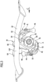
- the motor vehicle designated as a whole with 10 comprises a vehicle body 12 on which a trailer hitch 20 according to the invention is mounted in a rear area 14, which has a cross member 22 covered by a bumper unit 16 and extending transversely to a longitudinal direction 18 of the vehicle body 12 and transversely over the rear area 14 and has side supports 24 which extend approximately parallel to the longitudinal direction 18 of the vehicle body 12 along body wall sections 26 and are fixed to them, which, together with the cross member 22, form a holding unit 28 which is partly covered by the vehicle body 12 and partly by the bumper unit 16 .
- the swivel bearing unit 30 makes it possible to move the ball neck 40 from one in 2 and 3 illustrated working position A, in which a ball center axis 48 of the coupling ball 46 is in a vertical vehicle longitudinal center plane FL parallel to the longitudinal direction 18, about a transverse, in particular oblique, preferably at an acute angle, to the vehicle longitudinal center plane FL pivot axis 50 into an in 3 illustrated rest position R, in which a central section 52 of the ball neck extends transversely to the longitudinal center plane FL of the vehicle and the coupling ball 46 lies to the side of the vehicle's longitudinal center plane FL, as in FIG 3 shown.
- the ball neck 40 is arranged in the rest position R in a position covered by the bumper unit 16 of the vehicle body 12 to the side of the longitudinal center plane FL of the vehicle.
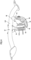
- the support base 32 comprises a flange unit 62, on which the pivot bearing unit 30 is mounted, and starting from the flange unit 62 extending support members 64 and 66, as in Figs Figures 3 to 11 shown, starting from the flange unit 62 increasingly extend away from each other and in particular starting from a geometric center plane 68 of the flange unit 62 with increasing distance from the flange unit 62 at increasing distance from the center plane 68, as in the 6 and 9 shown.
- the geometric center plane 68 as in 6 shown, obliquely to a central axis 128 of the cross member 22 in the area of the cross member 22 that carries the holding base 32.
- the holding base 32 is formed by two elements 74 and 76 made of flat material, which have two flange elements 84 and 86 which, for example, abut one another with contact sides 94 and 96 facing one another, with the contact sides 94 and 96 each contacting the central plane 68 of the flange unit 62 adjoin, so that both contact sides 94 and 96 are ultimately arranged adjacent to the geometric center plane 68.
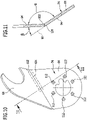
- the element 74 comprises the holding element 64, which is bent relative to the flange element 84 along a bending line 104 and thus, starting from the bending line 104, at an angle to the central plane 68 and with increasing distance from the bending line 104 with increasing distance from the center plane 68 runs.
- the holding element 64 is preferably also a part of the flat material from which the element 74 is formed, so that—as in FIG Figures 8 to 11 shown - the flange element 84 and the holding element 64 are each flat material parts which merge into one another in one piece via a bending region 102 predetermined by the bending line 104, the flat material parts enclosing an obtuse angle ⁇ with one another which is in the range from 100 degrees to 170 degrees.
- the acute angle ⁇ at which the holding element 64 runs relative to the contact side 94 and thus to the central plane 68 is in the range from 10 degrees to 80 degrees, preferably in the range from 20 degrees to 60 degrees.
- the holding element 66 is also - as in 8 and 9 shown - portion of member 76 including flange member 86 relative to which retaining member 66 is angled from a bend line 106 .
- the element 76 is also formed from flat material, with the flange element 86 and the holding element 66 merging into one another via a bending region 108 predetermined by the bending line 106 and the flat material parts enclose an obtuse angle with one another, which is also in the range from 100 degrees to 170 degrees.
- the holding element 66 extends relative to the contact side 96 of the flange element 66 starting from the bending line 106 at an angle which is in the range from 10 degrees to 80 degrees, preferably in the range from 20 degrees to 60 degrees.
- the holding element 66 also extends, starting from the bending line 106, at an acute angle relative to the center plane 68.
- the bending lines 104 and 106 do not run parallel to one another, but rather their projection onto the central plane 68, which in 6 represents the plane of the drawing, results in an acute angle ⁇ between the bend lines 104 and 106, which is in the range between 15 degrees and 140 degrees, preferably in the range between 40 degrees and 100 degrees.
- the flange elements 84 and 86 are in turn provided with identically arranged openings 112, which are arranged around the pivot axis 50, preferably on a circular line around the pivot axis 50, and are used to accommodate mounting screws with which the pivot bearing unit 30 can be mounted on the flange unit 62 .
- flange elements 84 and 86 for example by spot welding or by gluing areal to connect to each other.
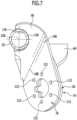
- the holding elements 64, 66 are provided with cross member mounts 114, 116 ( Figures 7 to 9 ), which are produced by cutouts from the flat material forming the holding elements 64, 66, the course of edge contours 124, 126 of the crossmember mounts 114 and 116 formed by the cutouts being adapted to an outer peripheral surface 118 of the crossmember 22, on which the crossmember mounts 114 and 116 preferably lie in linear contact with their edge contours 124 and 126, and are welded to the cross member 22 along the linearly adjacent edge contours 124 and 126, with a linear welded connection preferably being produced.
- the cross member mounts 114 and 116 are preferably designed in such a way that, as in 6 and 7 shown, include the outer circumferential surface 118 of the cross member 22 in a circumferential area which extends over an angular range of more than 120 degrees about a central axis of the cross member, preferably an angular range of more than 150 degrees about the central axis 128 of the cross member 22.
- the holding base 32 allows a stable and, in particular, rigid connection between the holding base 32 and the cross member 22 due to the holding elements 64 and 66, which are spread apart from one another, and is also easy to produce in that it comprises two elements 74 and 76 made of a plate-shaped flat material, in which the retaining element 64, 66 is bent relative to the flange element 84 and 86 forming the flange unit 62 along a bending line 104, 106 in order to, on the one hand, with flange elements 84 and 86 which are connected to one another and abutting to form the flange unit 62, on the one hand, prevent the spreading course of the retaining elements 84 and 86 to obtain.
- the support base 32' comprises a flange unit 62', which is formed from more than two, for example four, elements 74', 75', 76' and 77' made of flat material, each of the elements 74' to 77' has a holding element 64', 65', 66' and 67' and a corresponding flange element 84', 85', 86', 87'.
- All flange elements 84′, 85′, 86′, 87′ run parallel to the central plane 68′ and in particular lie flat against one another in order to form the flange unit 62′, which carries the bearing unit 30.
- the holding elements 64', 65', 66' and 67' enclose an obtuse angle with the flange elements 84', 85', 86', 87'.
- the retaining members 64', 65', 66', 67' are spaced increasingly apart from each other as the distance from the flange unit 62' increases.
Landscapes
- Engineering & Computer Science (AREA)
- Transportation (AREA)
- Mechanical Engineering (AREA)
- Rolling Contact Bearings (AREA)
- Connection Of Plates (AREA)
- Vehicle Body Suspensions (AREA)
- Body Structure For Vehicles (AREA)
- Clamps And Clips (AREA)
Claims (15)
- Attelage pour véhicules à moteur, comportant une traverse (22) pouvant être reliée à une carrosserie de véhicule à moteur (12) et une unité de support (30), laquelle portant un col porte-boule (40), qui est relié par une première extrémité (42) à l'unité de support (30) et qui porte par une deuxième extrémité (44) une boule d'attelage (46), et une base de retenue (32) portant l'unité de support (30) et reliée à la traverse (22), dans lequel la base de retenue (32) présente une unité bride (62) destinée à loger l'unité de support (30) ainsi que deux éléments de retenue (64, 66) partant de l'unité bride (62) et s'étendant à distance l'un de l'autre, et qui agissent sur la traverse (22), dans lequel la base de retenue (32) est formée par deux éléments (74, 76) composés d'un matériau plat, parmi lesquels chacun comporte un élément bride (84, 86), lequel contribue à former l'unité bride (62), et parmi lesquels chacun forme l'un des éléments de retenue (64, 66) qui s'étendent de l'unité bride (62) en direction de la traverse (22) et dans lequel chacun des éléments de retenue (64, 66) est relié fixement à l'élément bride (84, 86) respectif, dans lequel les éléments de retenue (64, 66) sont repliés par rapport aux éléments bride (84, 86) correspondants le long d'une ligne de pliage (104, 106), dans lequel l'élément de retenue (64, 66) et l'élément bride (84, 86) respectif de l'élément (74, 76) respectif forment ensemble un angle obtus,
caractérisé en ce que l'unité de support (30) est une unité palier pivotant (30), laquelle est montée sur l'unité bride (62), que la projection des lignes de pliage (104, 106) des éléments (74, 76) sur le plan médian (68) donne lieu à un tracé sur lequel les lignes de pliage (104', 106') projetées se croisent. - Attelage selon la revendication 1, caractérisé en ce que l'unité bride (62) est formée des éléments bride (84, 86), de telle sorte que les éléments bride (84, 86) s'appliquent les uns contre les autres par des faces d'appui (94, 96) tournées les unes vers les autres.
- Attelage selon la revendication 1 ou 2, caractérisé en ce que chacun des éléments de retenue (64, 66) est d'une seule pièce avec l'élément bride (84, 86) respectif.
- Attelage selon l'une quelconque des revendications 1 à 3, caractérisé en ce que chacun des éléments de retenue (64, 66) est agencé par rapport à l'élément bride (84, 86) correspondant de manière à passer dans l'élément bride (84, 86) respectif par l'intermédiaire d'une zone de pliage (102, 108).
- Attelage selon l'une quelconque des revendications précédentes, caractérisé en ce que les éléments de retenue (64, 66) s'étendent en s'écartant de plus en plus l'un de l'autre à mesure que croît leur écart par rapport à l'unité bride (62).
- Attelage selon l'une quelconque des revendications précédentes, caractérisé en ce que les éléments de retenue (64, 66) respectifs s'étendent en s'écartant de plus en plus d'un plan médian (68) de l'unité bride (62) à mesure qu'ils s'étendent de plus en plus à distance de l'unité bride (62).
- Attelage selon l'une quelconque des revendications précédentes, caractérisé en ce que les éléments de retenue (64, 66) s'étendent de manière à former un angle aigu avec un plan médian (68) de l'unité bride (68).
- Attelage selon l'une quelconque des revendications précédentes, caractérisé en ce que l'angle obtus entre l'élément de retenue (64, 66) respectif et l'élément bride (84, 86) respectif se situe dans la plage comprise entre 100 degrés et 170 degrés.
- Attelage selon l'une quelconque des revendications précédentes, caractérisé en ce que les lignes de pliage (104', 106') projetées forment ensemble un angle aigu et en ce qu'en particulier l'angle aigu se situe dans la plage comprise entre 15 degrés et 140 degrés.
- Attelage selon l'une quelconque des revendications précédentes, caractérisé en ce que les éléments de retenue (64, 66) s'appliquent contre une surface périphérique extérieure (118) de la traverse (22) .
- Attelage selon la revendication 10, caractérisé en ce que les éléments de retenue (64, 66) sont pourvus de logements de traverse (114, 116), qui s'appliquent contre la surface périphérique extérieure (118) de la traverse (22).
- Attelage selon l'une quelconque des revendications précédentes, caractérisé en ce que les logements de traverse (114, 116) sont réalisés sous la forme de découpes ménagées dans les éléments de retenue (64, 66), de sorte que les éléments de retenue (64, 66) s'étendent dans la zone des logements de traverse (114, 116) transversalement à la traverse (22), en particulier selon un angle différent de 90°.
- Attelage selon l'une quelconque des revendications précédentes, caractérisé en ce que les logements de traverse (114, 116) sont formés par des contours marginaux des éléments de retenue (64, 66), lesquels s'appliquent contre la surface périphérique extérieure (118) de la traverse (22).
- Attelage selon la revendication 13, caractérisé en ce que les logements de traverse (114, 116) s'appliquent le long de leurs contours marginaux contre la surface périphérique extérieure (118).
- Attelage selon l'une quelconque des revendications 11 à 14, caractérisé en ce que les logements de traverse (114, 116) entourent la surface périphérique extérieure (118) de la traverse (22) sur toute l'étendue d'une plage angulaire d'au moins 120 degrés, par rapport à un axe médian de la traverse (22), et en ce qu'en particulier les logements de traverse (114, 116) entourent la surface périphérique extérieure (118) de la traverse (22) sur un angle d'au moins 150°, mieux encore d'au moins 180°, et en ce qu'en particulier les logements de traverse (114, 116) sont soudés à la traverse (22) de manière linéaire le long de leur contour marginal.
Applications Claiming Priority (1)
| Application Number | Priority Date | Filing Date | Title |
|---|---|---|---|
| DE102015100490.9A DE102015100490A1 (de) | 2015-01-14 | 2015-01-14 | Anhängekupplung |
Publications (3)
| Publication Number | Publication Date |
|---|---|
| EP3045328A1 EP3045328A1 (fr) | 2016-07-20 |
| EP3045328B1 EP3045328B1 (fr) | 2019-04-03 |
| EP3045328B2 true EP3045328B2 (fr) | 2023-03-15 |
Family
ID=55129650
Family Applications (1)
| Application Number | Title | Priority Date | Filing Date |
|---|---|---|---|
| EP16151064.9A Active EP3045328B2 (fr) | 2015-01-14 | 2016-01-13 | Attelage |
Country Status (3)
| Country | Link |
|---|---|
| US (1) | US9849741B2 (fr) |
| EP (1) | EP3045328B2 (fr) |
| DE (1) | DE102015100490A1 (fr) |
Families Citing this family (4)
| Publication number | Priority date | Publication date | Assignee | Title |
|---|---|---|---|---|
| DE102016117017A1 (de) | 2016-09-09 | 2018-03-15 | Westfalia-Automotive Gmbh | Anhängekupplung mit einem Kupplungsarm |
| DE102017121369A1 (de) | 2017-09-14 | 2019-03-14 | ACPS Automotive GmbH | Anhängekupplung |
| DE102017121357A1 (de) * | 2017-09-14 | 2019-03-14 | ACPS Automotive GmbH | Anhängekupplung |
| FR3071436B1 (fr) * | 2017-09-26 | 2020-04-03 | Renault S.A.S | Agencement de montage d'une traverse d'attelage sur une caisse de vehicule automobile. |
Citations (4)
| Publication number | Priority date | Publication date | Assignee | Title |
|---|---|---|---|---|
| US2944836A (en) † | 1958-08-07 | 1960-07-12 | Dalton Foundries Inc | Retractable trailer hitches |
| EP0799732A1 (fr) † | 1996-04-01 | 1997-10-08 | ORIS FAHRZEUGTEILE HANS RIEHLE GmbH | Attelage de remorque |
| EP1428697A1 (fr) † | 2002-11-13 | 2004-06-16 | Westfalia Automotive GmbH & Co. KG | Dipositif d'attelage |
| WO2006068479A1 (fr) † | 2004-12-24 | 2006-06-29 | Thule Towing Systems B.V. | Attelage de remorquage retractable |
Family Cites Families (15)
| Publication number | Priority date | Publication date | Assignee | Title |
|---|---|---|---|---|
| US2642295A (en) | 1952-09-08 | 1953-06-16 | Fulton Co | Vehicle tow coupling |
| SE390143B (sv) | 1975-05-06 | 1976-12-06 | Volvo Ab | Draganordning ffor motorfordon |
| DE102004004503B4 (de) * | 2004-01-22 | 2022-01-20 | ACPS Automotive GmbH | Anhängekupplung |
| DE102005032474A1 (de) * | 2005-07-07 | 2007-01-11 | Oris Fahrzeugteile Hans Riehle Gmbh | Anhängevorrichtung |
| DE102005053177A1 (de) * | 2005-11-03 | 2007-05-10 | Scambia Industrial Developments Aktiengesellschaft | Betätigungseinrichtung |
| DE102006035261A1 (de) * | 2006-07-29 | 2008-01-31 | Scambia Industrial Developments Aktiengesellschaft | Anhängekupplung |
| JP4377930B2 (ja) * | 2007-06-21 | 2009-12-02 | 本田技研工業株式会社 | 車体パネル |
| DE102008012622A1 (de) * | 2008-02-28 | 2009-09-10 | Scambia Industrial Developments Aktiengesellschaft | Anhängekupplung |
| DE102008030626A1 (de) * | 2008-06-23 | 2009-12-31 | Scambia Industrial Developments Aktiengesellschaft | Anhängekupplung |
| JP5327319B2 (ja) * | 2009-05-22 | 2013-10-30 | トヨタ自動車株式会社 | 車両ボディ構造 |
| DE102009035334A1 (de) * | 2009-07-21 | 2011-01-27 | Scambia Industrial Developments Aktiengesellschaft | Anhängekupplung für Kraftfahrzeuge |
| DE102010054208B4 (de) | 2010-12-11 | 2015-05-28 | Westfalia-Automotive Gmbh | Steuereinrichtung für eine Anhängerkupplung eines Kraftfahrzeugs |
| DE102011053506A1 (de) * | 2011-09-12 | 2013-03-14 | Scambia Holdings Cyprus Ltd. | Anhängekupplung |
| FR2983125B1 (fr) * | 2011-11-25 | 2014-05-02 | Ur Ben | Ensemble d'attelage pour vehicule automobile de traction |
| DE102013100777A1 (de) | 2013-01-25 | 2014-07-31 | Scambia Holdings Cyprus Limited | Anhängekupplung |
-
2015
- 2015-01-14 DE DE102015100490.9A patent/DE102015100490A1/de not_active Ceased
-
2016
- 2016-01-13 US US14/994,891 patent/US9849741B2/en active Active
- 2016-01-13 EP EP16151064.9A patent/EP3045328B2/fr active Active
Patent Citations (4)
| Publication number | Priority date | Publication date | Assignee | Title |
|---|---|---|---|---|
| US2944836A (en) † | 1958-08-07 | 1960-07-12 | Dalton Foundries Inc | Retractable trailer hitches |
| EP0799732A1 (fr) † | 1996-04-01 | 1997-10-08 | ORIS FAHRZEUGTEILE HANS RIEHLE GmbH | Attelage de remorque |
| EP1428697A1 (fr) † | 2002-11-13 | 2004-06-16 | Westfalia Automotive GmbH & Co. KG | Dipositif d'attelage |
| WO2006068479A1 (fr) † | 2004-12-24 | 2006-06-29 | Thule Towing Systems B.V. | Attelage de remorquage retractable |
Also Published As
| Publication number | Publication date |
|---|---|
| EP3045328B1 (fr) | 2019-04-03 |
| DE102015100490A1 (de) | 2016-07-14 |
| US9849741B2 (en) | 2017-12-26 |
| US20160200158A1 (en) | 2016-07-14 |
| EP3045328A1 (fr) | 2016-07-20 |
Similar Documents
| Publication | Publication Date | Title |
|---|---|---|
| EP0518165B1 (fr) | Superstructure de véhicule | |
| EP2095978B1 (fr) | Attelage | |
| EP2322332B1 (fr) | Bétonnière avec un châssis | |
| EP3045328B2 (fr) | Attelage | |
| WO2017016651A1 (fr) | Dispositif de retenue d'un composant | |
| WO2015007631A1 (fr) | Structure de dossier de siège de véhicule et siège de véhicule | |
| DE102011112418A1 (de) | Vorrichtung zur Befestigung einer Kopfstütze an einem Fahrzeugsitz und Fahrzeugsitz mit Kopfstütze | |
| EP2759422B1 (fr) | Attelage | |
| EP2508407A1 (fr) | Structure, en particulier pour les installations électriques dans un véhicule sur rail, et procédé de fabrication de cette structure | |
| EP2730457A1 (fr) | Entraînement d'un dispositif de réglage de siège pour véhicules automobiles | |
| WO2016026745A1 (fr) | Agencement de support de groupe | |
| DE102015118505B4 (de) | Befestigungsvorrichtung | |
| EP3964369B1 (fr) | Système de montage | |
| DE102017117502B4 (de) | Lenksäulen-Klemmträger sowie Verstellvorrichtung | |
| DE102008026618B4 (de) | Positioniereinrichtung | |
| DE102014218605B4 (de) | Vorrichtung zur Befestigung einer Hinterachse an einem karosseriebaufesten Querträger eines Kraftfahrzeugs und Anordnung einer solchen Vorrichtung in einem Kraftfahrzeug | |
| DE19623691C2 (de) | Haltevorrichtung für Fahrzeugzubehör oder Fahrzeugzusatzeinrichtungen | |
| DE102021133348A1 (de) | Anhängekupplung für Kraftfahrzeuge | |
| DE102022119905A1 (de) | Anhängekupplung | |
| DE102004020746A1 (de) | Schutzvorrichtung für Kraftfahrzeuge | |
| DE102022119904A1 (de) | Anhängekupplung | |
| DE102020111069A1 (de) | Blattfeder | |
| EP2390119A1 (fr) | Dispositif de montage à l'arrière | |
| DE102009005477A1 (de) | Halterungseinrichtung für eine Schutzwandanordnung und Schutzwandanordnung mit einer derartigen Halterungseinrichtung | |
| DE29504839U1 (de) | Verbinder für Gitterkabelbahnen |
Legal Events
| Date | Code | Title | Description |
|---|---|---|---|
| PUAI | Public reference made under article 153(3) epc to a published international application that has entered the european phase |
Free format text: ORIGINAL CODE: 0009012 |
|
| AK | Designated contracting states |
Kind code of ref document: A1 Designated state(s): AL AT BE BG CH CY CZ DE DK EE ES FI FR GB GR HR HU IE IS IT LI LT LU LV MC MK MT NL NO PL PT RO RS SE SI SK SM TR |
|
| AX | Request for extension of the european patent |
Extension state: BA ME |
|
| STAA | Information on the status of an ep patent application or granted ep patent |
Free format text: STATUS: REQUEST FOR EXAMINATION WAS MADE |
|
| 17P | Request for examination filed |
Effective date: 20170119 |
|
| RBV | Designated contracting states (corrected) |
Designated state(s): AL AT BE BG CH CY CZ DE DK EE ES FI FR GB GR HR HU IE IS IT LI LT LU LV MC MK MT NL NO PL PT RO RS SE SI SK SM TR |
|
| RAP1 | Party data changed (applicant data changed or rights of an application transferred) |
Owner name: BOSAL ACPS HOLDING 2 B.V. |
|
| GRAP | Despatch of communication of intention to grant a patent |
Free format text: ORIGINAL CODE: EPIDOSNIGR1 |
|
| STAA | Information on the status of an ep patent application or granted ep patent |
Free format text: STATUS: GRANT OF PATENT IS INTENDED |
|
| RIC1 | Information provided on ipc code assigned before grant |
Ipc: B60D 1/06 20060101AFI20181002BHEP Ipc: B60D 1/48 20060101ALI20181002BHEP |
|
| INTG | Intention to grant announced |
Effective date: 20181026 |
|
| GRAS | Grant fee paid |
Free format text: ORIGINAL CODE: EPIDOSNIGR3 |
|
| GRAA | (expected) grant |
Free format text: ORIGINAL CODE: 0009210 |
|
| STAA | Information on the status of an ep patent application or granted ep patent |
Free format text: STATUS: THE PATENT HAS BEEN GRANTED |
|
| AK | Designated contracting states |
Kind code of ref document: B1 Designated state(s): AL AT BE BG CH CY CZ DE DK EE ES FI FR GB GR HR HU IE IS IT LI LT LU LV MC MK MT NL NO PL PT RO RS SE SI SK SM TR |
|
| REG | Reference to a national code |
Ref country code: GB Ref legal event code: FG4D Free format text: NOT ENGLISH |
|
| REG | Reference to a national code |
Ref country code: CH Ref legal event code: EP Ref country code: AT Ref legal event code: REF Ref document number: 1115263 Country of ref document: AT Kind code of ref document: T Effective date: 20190415 |
|
| REG | Reference to a national code |
Ref country code: DE Ref legal event code: R096 Ref document number: 502016003944 Country of ref document: DE |
|
| REG | Reference to a national code |
Ref country code: IE Ref legal event code: FG4D Free format text: LANGUAGE OF EP DOCUMENT: GERMAN |
|
| REG | Reference to a national code |
Ref country code: NL Ref legal event code: MP Effective date: 20190403 |
|
| REG | Reference to a national code |
Ref country code: LT Ref legal event code: MG4D |
|
| PG25 | Lapsed in a contracting state [announced via postgrant information from national office to epo] |
Ref country code: NL Free format text: LAPSE BECAUSE OF FAILURE TO SUBMIT A TRANSLATION OF THE DESCRIPTION OR TO PAY THE FEE WITHIN THE PRESCRIBED TIME-LIMIT Effective date: 20190403 |
|
| RAP2 | Party data changed (patent owner data changed or rights of a patent transferred) |
Owner name: ACPS AUTOMOTIVE GMBH |
|
| PG25 | Lapsed in a contracting state [announced via postgrant information from national office to epo] |
Ref country code: FI Free format text: LAPSE BECAUSE OF FAILURE TO SUBMIT A TRANSLATION OF THE DESCRIPTION OR TO PAY THE FEE WITHIN THE PRESCRIBED TIME-LIMIT Effective date: 20190403 Ref country code: NO Free format text: LAPSE BECAUSE OF FAILURE TO SUBMIT A TRANSLATION OF THE DESCRIPTION OR TO PAY THE FEE WITHIN THE PRESCRIBED TIME-LIMIT Effective date: 20190703 Ref country code: LT Free format text: LAPSE BECAUSE OF FAILURE TO SUBMIT A TRANSLATION OF THE DESCRIPTION OR TO PAY THE FEE WITHIN THE PRESCRIBED TIME-LIMIT Effective date: 20190403 Ref country code: HR Free format text: LAPSE BECAUSE OF FAILURE TO SUBMIT A TRANSLATION OF THE DESCRIPTION OR TO PAY THE FEE WITHIN THE PRESCRIBED TIME-LIMIT Effective date: 20190403 Ref country code: SE Free format text: LAPSE BECAUSE OF FAILURE TO SUBMIT A TRANSLATION OF THE DESCRIPTION OR TO PAY THE FEE WITHIN THE PRESCRIBED TIME-LIMIT Effective date: 20190403 Ref country code: ES Free format text: LAPSE BECAUSE OF FAILURE TO SUBMIT A TRANSLATION OF THE DESCRIPTION OR TO PAY THE FEE WITHIN THE PRESCRIBED TIME-LIMIT Effective date: 20190403 Ref country code: PT Free format text: LAPSE BECAUSE OF FAILURE TO SUBMIT A TRANSLATION OF THE DESCRIPTION OR TO PAY THE FEE WITHIN THE PRESCRIBED TIME-LIMIT Effective date: 20190803 Ref country code: AL Free format text: LAPSE BECAUSE OF FAILURE TO SUBMIT A TRANSLATION OF THE DESCRIPTION OR TO PAY THE FEE WITHIN THE PRESCRIBED TIME-LIMIT Effective date: 20190403 |
|
| PG25 | Lapsed in a contracting state [announced via postgrant information from national office to epo] |
Ref country code: LV Free format text: LAPSE BECAUSE OF FAILURE TO SUBMIT A TRANSLATION OF THE DESCRIPTION OR TO PAY THE FEE WITHIN THE PRESCRIBED TIME-LIMIT Effective date: 20190403 Ref country code: RS Free format text: LAPSE BECAUSE OF FAILURE TO SUBMIT A TRANSLATION OF THE DESCRIPTION OR TO PAY THE FEE WITHIN THE PRESCRIBED TIME-LIMIT Effective date: 20190403 Ref country code: BG Free format text: LAPSE BECAUSE OF FAILURE TO SUBMIT A TRANSLATION OF THE DESCRIPTION OR TO PAY THE FEE WITHIN THE PRESCRIBED TIME-LIMIT Effective date: 20190703 Ref country code: PL Free format text: LAPSE BECAUSE OF FAILURE TO SUBMIT A TRANSLATION OF THE DESCRIPTION OR TO PAY THE FEE WITHIN THE PRESCRIBED TIME-LIMIT Effective date: 20190403 Ref country code: GR Free format text: LAPSE BECAUSE OF FAILURE TO SUBMIT A TRANSLATION OF THE DESCRIPTION OR TO PAY THE FEE WITHIN THE PRESCRIBED TIME-LIMIT Effective date: 20190704 |
|
| PG25 | Lapsed in a contracting state [announced via postgrant information from national office to epo] |
Ref country code: IS Free format text: LAPSE BECAUSE OF FAILURE TO SUBMIT A TRANSLATION OF THE DESCRIPTION OR TO PAY THE FEE WITHIN THE PRESCRIBED TIME-LIMIT Effective date: 20190803 |
|
| REG | Reference to a national code |
Ref country code: DE Ref legal event code: R026 Ref document number: 502016003944 Country of ref document: DE |
|
| PLBI | Opposition filed |
Free format text: ORIGINAL CODE: 0009260 |
|
| PLAX | Notice of opposition and request to file observation + time limit sent |
Free format text: ORIGINAL CODE: EPIDOSNOBS2 |
|
| PG25 | Lapsed in a contracting state [announced via postgrant information from national office to epo] |
Ref country code: SK Free format text: LAPSE BECAUSE OF FAILURE TO SUBMIT A TRANSLATION OF THE DESCRIPTION OR TO PAY THE FEE WITHIN THE PRESCRIBED TIME-LIMIT Effective date: 20190403 Ref country code: DK Free format text: LAPSE BECAUSE OF FAILURE TO SUBMIT A TRANSLATION OF THE DESCRIPTION OR TO PAY THE FEE WITHIN THE PRESCRIBED TIME-LIMIT Effective date: 20190403 Ref country code: EE Free format text: LAPSE BECAUSE OF FAILURE TO SUBMIT A TRANSLATION OF THE DESCRIPTION OR TO PAY THE FEE WITHIN THE PRESCRIBED TIME-LIMIT Effective date: 20190403 Ref country code: RO Free format text: LAPSE BECAUSE OF FAILURE TO SUBMIT A TRANSLATION OF THE DESCRIPTION OR TO PAY THE FEE WITHIN THE PRESCRIBED TIME-LIMIT Effective date: 20190403 |
|
| 26 | Opposition filed |
Opponent name: WESTFALIA - AUTOMOTIVE GMBH Effective date: 20200102 |
|
| PG25 | Lapsed in a contracting state [announced via postgrant information from national office to epo] |
Ref country code: IT Free format text: LAPSE BECAUSE OF FAILURE TO SUBMIT A TRANSLATION OF THE DESCRIPTION OR TO PAY THE FEE WITHIN THE PRESCRIBED TIME-LIMIT Effective date: 20190403 Ref country code: SM Free format text: LAPSE BECAUSE OF FAILURE TO SUBMIT A TRANSLATION OF THE DESCRIPTION OR TO PAY THE FEE WITHIN THE PRESCRIBED TIME-LIMIT Effective date: 20190403 |
|
| PG25 | Lapsed in a contracting state [announced via postgrant information from national office to epo] |
Ref country code: TR Free format text: LAPSE BECAUSE OF FAILURE TO SUBMIT A TRANSLATION OF THE DESCRIPTION OR TO PAY THE FEE WITHIN THE PRESCRIBED TIME-LIMIT Effective date: 20190403 |
|
| PLBB | Reply of patent proprietor to notice(s) of opposition received |
Free format text: ORIGINAL CODE: EPIDOSNOBS3 |
|
| PG25 | Lapsed in a contracting state [announced via postgrant information from national office to epo] |
Ref country code: SI Free format text: LAPSE BECAUSE OF FAILURE TO SUBMIT A TRANSLATION OF THE DESCRIPTION OR TO PAY THE FEE WITHIN THE PRESCRIBED TIME-LIMIT Effective date: 20190403 |
|
| REG | Reference to a national code |
Ref country code: DE Ref legal event code: R081 Ref document number: 502016003944 Country of ref document: DE Owner name: ACPS AUTOMOTIVE GMBH, DE Free format text: FORMER OWNER: BOSAL ACPS HOLDING 2 B.V., VIANEN, NL Ref country code: DE Ref legal event code: R082 Ref document number: 502016003944 Country of ref document: DE Representative=s name: HOEGER, STELLRECHT & PARTNER PATENTANWAELTE MB, DE |
|
| PG25 | Lapsed in a contracting state [announced via postgrant information from national office to epo] |
Ref country code: MC Free format text: LAPSE BECAUSE OF FAILURE TO SUBMIT A TRANSLATION OF THE DESCRIPTION OR TO PAY THE FEE WITHIN THE PRESCRIBED TIME-LIMIT Effective date: 20190403 |
|
| REG | Reference to a national code |
Ref country code: CH Ref legal event code: PL |
|
| REG | Reference to a national code |
Ref country code: BE Ref legal event code: MM Effective date: 20200131 |
|
| PG25 | Lapsed in a contracting state [announced via postgrant information from national office to epo] |
Ref country code: LU Free format text: LAPSE BECAUSE OF NON-PAYMENT OF DUE FEES Effective date: 20200113 |
|
| PG25 | Lapsed in a contracting state [announced via postgrant information from national office to epo] |
Ref country code: BE Free format text: LAPSE BECAUSE OF NON-PAYMENT OF DUE FEES Effective date: 20200131 Ref country code: CH Free format text: LAPSE BECAUSE OF NON-PAYMENT OF DUE FEES Effective date: 20200131 Ref country code: LI Free format text: LAPSE BECAUSE OF NON-PAYMENT OF DUE FEES Effective date: 20200131 |
|
| PG25 | Lapsed in a contracting state [announced via postgrant information from national office to epo] |
Ref country code: IE Free format text: LAPSE BECAUSE OF NON-PAYMENT OF DUE FEES Effective date: 20200113 |
|
| REG | Reference to a national code |
Ref country code: AT Ref legal event code: MM01 Ref document number: 1115263 Country of ref document: AT Kind code of ref document: T Effective date: 20210113 |
|
| REG | Reference to a national code |
Ref country code: GB Ref legal event code: 732E Free format text: REGISTERED BETWEEN 20220224 AND 20220302 |
|
| PG25 | Lapsed in a contracting state [announced via postgrant information from national office to epo] |
Ref country code: AT Free format text: LAPSE BECAUSE OF NON-PAYMENT OF DUE FEES Effective date: 20210113 |
|
| PG25 | Lapsed in a contracting state [announced via postgrant information from national office to epo] |
Ref country code: MT Free format text: LAPSE BECAUSE OF FAILURE TO SUBMIT A TRANSLATION OF THE DESCRIPTION OR TO PAY THE FEE WITHIN THE PRESCRIBED TIME-LIMIT Effective date: 20190403 Ref country code: CY Free format text: LAPSE BECAUSE OF FAILURE TO SUBMIT A TRANSLATION OF THE DESCRIPTION OR TO PAY THE FEE WITHIN THE PRESCRIBED TIME-LIMIT Effective date: 20190403 |
|
| PG25 | Lapsed in a contracting state [announced via postgrant information from national office to epo] |
Ref country code: MK Free format text: LAPSE BECAUSE OF FAILURE TO SUBMIT A TRANSLATION OF THE DESCRIPTION OR TO PAY THE FEE WITHIN THE PRESCRIBED TIME-LIMIT Effective date: 20190403 |
|
| APAH | Appeal reference modified |
Free format text: ORIGINAL CODE: EPIDOSCREFNO |
|
| APBM | Appeal reference recorded |
Free format text: ORIGINAL CODE: EPIDOSNREFNO |
|
| APBP | Date of receipt of notice of appeal recorded |
Free format text: ORIGINAL CODE: EPIDOSNNOA2O |
|
| APBU | Appeal procedure closed |
Free format text: ORIGINAL CODE: EPIDOSNNOA9O |
|
| REG | Reference to a national code |
Ref country code: DE Ref legal event code: R081 Ref document number: 502016003944 Country of ref document: DE Owner name: ACPS AUTOMOTIVE GMBH, DE Free format text: FORMER OWNER: ACPS AUTOMOTIVE GMBH, 71706 MARKGROENINGEN, DE |
|
| RAP4 | Party data changed (patent owner data changed or rights of a patent transferred) |
Owner name: ACPS AUTOMOTIVE GMBH |
|
| PUAH | Patent maintained in amended form |
Free format text: ORIGINAL CODE: 0009272 |
|
| STAA | Information on the status of an ep patent application or granted ep patent |
Free format text: STATUS: PATENT MAINTAINED AS AMENDED |
|
| 27A | Patent maintained in amended form |
Effective date: 20230315 |
|
| AK | Designated contracting states |
Kind code of ref document: B2 Designated state(s): AL AT BE BG CH CY CZ DE DK EE ES FI FR GB GR HR HU IE IS IT LI LT LU LV MC MK MT NL NO PL PT RO RS SE SI SK SM TR |
|
| REG | Reference to a national code |
Ref country code: DE Ref legal event code: R102 Ref document number: 502016003944 Country of ref document: DE |
|
| P01 | Opt-out of the competence of the unified patent court (upc) registered |
Effective date: 20230517 |
|
| PGFP | Annual fee paid to national office [announced via postgrant information from national office to epo] |
Ref country code: GB Payment date: 20260123 Year of fee payment: 11 |
|
| PGFP | Annual fee paid to national office [announced via postgrant information from national office to epo] |
Ref country code: DE Payment date: 20260121 Year of fee payment: 11 |
|
| PGFP | Annual fee paid to national office [announced via postgrant information from national office to epo] |
Ref country code: FR Payment date: 20260123 Year of fee payment: 11 |
|
| PGFP | Annual fee paid to national office [announced via postgrant information from national office to epo] |
Ref country code: CZ Payment date: 20260108 Year of fee payment: 11 |