EP3045359B1 - Dispositif de frein électrique - Google Patents
Dispositif de frein électrique Download PDFInfo
- Publication number
- EP3045359B1 EP3045359B1 EP14842713.1A EP14842713A EP3045359B1 EP 3045359 B1 EP3045359 B1 EP 3045359B1 EP 14842713 A EP14842713 A EP 14842713A EP 3045359 B1 EP3045359 B1 EP 3045359B1
- Authority
- EP
- European Patent Office
- Prior art keywords
- emergency braking
- value
- brake
- flux weakening
- braking force
- Prior art date
- Legal status (The legal status is an assumption and is not a legal conclusion. Google has not performed a legal analysis and makes no representation as to the accuracy of the status listed.)
- Not-in-force
Links
- 230000004907 flux Effects 0.000 claims description 49
- 230000003313 weakening effect Effects 0.000 claims description 49
- 238000001514 detection method Methods 0.000 claims description 34
- 230000007246 mechanism Effects 0.000 claims description 30
- 238000012544 monitoring process Methods 0.000 claims description 8
- 230000009467 reduction Effects 0.000 description 15
- 238000010586 diagram Methods 0.000 description 7
- 238000000034 method Methods 0.000 description 7
- 238000013507 mapping Methods 0.000 description 5
- 238000003780 insertion Methods 0.000 description 4
- 230000037431 insertion Effects 0.000 description 4
- 230000004043 responsiveness Effects 0.000 description 4
- 230000008569 process Effects 0.000 description 3
- 238000004088 simulation Methods 0.000 description 3
- 238000012360 testing method Methods 0.000 description 3
- RYGMFSIKBFXOCR-UHFFFAOYSA-N Copper Chemical compound [Cu] RYGMFSIKBFXOCR-UHFFFAOYSA-N 0.000 description 2
- 238000004364 calculation method Methods 0.000 description 2
- 229910052802 copper Inorganic materials 0.000 description 2
- 239000010949 copper Substances 0.000 description 2
- 230000005415 magnetization Effects 0.000 description 2
- 238000012986 modification Methods 0.000 description 2
- 230000004048 modification Effects 0.000 description 2
- 238000003825 pressing Methods 0.000 description 2
- 238000005096 rolling process Methods 0.000 description 2
- 239000004065 semiconductor Substances 0.000 description 2
- 238000010276 construction Methods 0.000 description 1
- 230000000694 effects Effects 0.000 description 1
- 230000004044 response Effects 0.000 description 1
- 230000001360 synchronised effect Effects 0.000 description 1
Images



Classifications
-
- F—MECHANICAL ENGINEERING; LIGHTING; HEATING; WEAPONS; BLASTING
- F16—ENGINEERING ELEMENTS AND UNITS; GENERAL MEASURES FOR PRODUCING AND MAINTAINING EFFECTIVE FUNCTIONING OF MACHINES OR INSTALLATIONS; THERMAL INSULATION IN GENERAL
- F16D—COUPLINGS FOR TRANSMITTING ROTATION; CLUTCHES; BRAKES
- F16D65/00—Parts or details
- F16D65/14—Actuating mechanisms for brakes; Means for initiating operation at a predetermined position
- F16D65/16—Actuating mechanisms for brakes; Means for initiating operation at a predetermined position arranged in or on the brake
- F16D65/18—Actuating mechanisms for brakes; Means for initiating operation at a predetermined position arranged in or on the brake adapted for drawing members together, e.g. for disc brakes
-
- B—PERFORMING OPERATIONS; TRANSPORTING
- B60—VEHICLES IN GENERAL
- B60L—PROPULSION OF ELECTRICALLY-PROPELLED VEHICLES; SUPPLYING ELECTRIC POWER FOR AUXILIARY EQUIPMENT OF ELECTRICALLY-PROPELLED VEHICLES; ELECTRODYNAMIC BRAKE SYSTEMS FOR VEHICLES IN GENERAL; MAGNETIC SUSPENSION OR LEVITATION FOR VEHICLES; MONITORING OPERATING VARIABLES OF ELECTRICALLY-PROPELLED VEHICLES; ELECTRIC SAFETY DEVICES FOR ELECTRICALLY-PROPELLED VEHICLES
- B60L7/00—Electrodynamic brake systems for vehicles in general
-
- H—ELECTRICITY
- H02—GENERATION; CONVERSION OR DISTRIBUTION OF ELECTRIC POWER
- H02K—DYNAMO-ELECTRIC MACHINES
- H02K7/00—Arrangements for handling mechanical energy structurally associated with dynamo-electric machines, e.g. structural association with mechanical driving motors or auxiliary dynamo-electric machines
- H02K7/06—Means for converting reciprocating motion into rotary motion or vice versa
-
- H—ELECTRICITY
- H02—GENERATION; CONVERSION OR DISTRIBUTION OF ELECTRIC POWER
- H02P—CONTROL OR REGULATION OF ELECTRIC MOTORS, ELECTRIC GENERATORS OR DYNAMO-ELECTRIC CONVERTERS; CONTROLLING TRANSFORMERS, REACTORS OR CHOKE COILS
- H02P23/00—Arrangements or methods for the control of AC motors characterised by a control method other than vector control
- H02P23/0086—Arrangements or methods for the control of AC motors characterised by a control method other than vector control specially adapted for high speeds, e.g. above nominal speed
- H02P23/009—Arrangements or methods for the control of AC motors characterised by a control method other than vector control specially adapted for high speeds, e.g. above nominal speed using field weakening
-
- H—ELECTRICITY
- H02—GENERATION; CONVERSION OR DISTRIBUTION OF ELECTRIC POWER
- H02P—CONTROL OR REGULATION OF ELECTRIC MOTORS, ELECTRIC GENERATORS OR DYNAMO-ELECTRIC CONVERTERS; CONTROLLING TRANSFORMERS, REACTORS OR CHOKE COILS
- H02P3/00—Arrangements for stopping or slowing electric motors, generators, or dynamo-electric converters
- H02P3/06—Arrangements for stopping or slowing electric motors, generators, or dynamo-electric converters for stopping or slowing an individual dynamo-electric motor or dynamo-electric converter
- H02P3/18—Arrangements for stopping or slowing electric motors, generators, or dynamo-electric converters for stopping or slowing an individual dynamo-electric motor or dynamo-electric converter for stopping or slowing an AC motor
-
- F—MECHANICAL ENGINEERING; LIGHTING; HEATING; WEAPONS; BLASTING
- F16—ENGINEERING ELEMENTS AND UNITS; GENERAL MEASURES FOR PRODUCING AND MAINTAINING EFFECTIVE FUNCTIONING OF MACHINES OR INSTALLATIONS; THERMAL INSULATION IN GENERAL
- F16D—COUPLINGS FOR TRANSMITTING ROTATION; CLUTCHES; BRAKES
- F16D2121/00—Type of actuator operation force
- F16D2121/18—Electric or magnetic
- F16D2121/24—Electric or magnetic using motors
-
- F—MECHANICAL ENGINEERING; LIGHTING; HEATING; WEAPONS; BLASTING
- F16—ENGINEERING ELEMENTS AND UNITS; GENERAL MEASURES FOR PRODUCING AND MAINTAINING EFFECTIVE FUNCTIONING OF MACHINES OR INSTALLATIONS; THERMAL INSULATION IN GENERAL
- F16D—COUPLINGS FOR TRANSMITTING ROTATION; CLUTCHES; BRAKES
- F16D2125/00—Components of actuators
- F16D2125/18—Mechanical mechanisms
- F16D2125/20—Mechanical mechanisms converting rotation to linear movement or vice versa
- F16D2125/34—Mechanical mechanisms converting rotation to linear movement or vice versa acting in the direction of the axis of rotation
- F16D2125/40—Screw-and-nut
-
- F—MECHANICAL ENGINEERING; LIGHTING; HEATING; WEAPONS; BLASTING
- F16—ENGINEERING ELEMENTS AND UNITS; GENERAL MEASURES FOR PRODUCING AND MAINTAINING EFFECTIVE FUNCTIONING OF MACHINES OR INSTALLATIONS; THERMAL INSULATION IN GENERAL
- F16D—COUPLINGS FOR TRANSMITTING ROTATION; CLUTCHES; BRAKES
- F16D2125/00—Components of actuators
- F16D2125/18—Mechanical mechanisms
- F16D2125/44—Mechanical mechanisms transmitting rotation
- F16D2125/46—Rotating members in mutual engagement
- F16D2125/48—Rotating members in mutual engagement with parallel stationary axes, e.g. spur gears
-
- F—MECHANICAL ENGINEERING; LIGHTING; HEATING; WEAPONS; BLASTING
- F16—ENGINEERING ELEMENTS AND UNITS; GENERAL MEASURES FOR PRODUCING AND MAINTAINING EFFECTIVE FUNCTIONING OF MACHINES OR INSTALLATIONS; THERMAL INSULATION IN GENERAL
- F16D—COUPLINGS FOR TRANSMITTING ROTATION; CLUTCHES; BRAKES
- F16D2125/00—Components of actuators
- F16D2125/18—Mechanical mechanisms
- F16D2125/44—Mechanical mechanisms transmitting rotation
- F16D2125/46—Rotating members in mutual engagement
- F16D2125/52—Rotating members in mutual engagement with non-parallel stationary axes, e.g. worm or bevel gears
-
- Y—GENERAL TAGGING OF NEW TECHNOLOGICAL DEVELOPMENTS; GENERAL TAGGING OF CROSS-SECTIONAL TECHNOLOGIES SPANNING OVER SEVERAL SECTIONS OF THE IPC; TECHNICAL SUBJECTS COVERED BY FORMER USPC CROSS-REFERENCE ART COLLECTIONS [XRACs] AND DIGESTS
- Y02—TECHNOLOGIES OR APPLICATIONS FOR MITIGATION OR ADAPTATION AGAINST CLIMATE CHANGE
- Y02T—CLIMATE CHANGE MITIGATION TECHNOLOGIES RELATED TO TRANSPORTATION
- Y02T10/00—Road transport of goods or passengers
- Y02T10/60—Other road transportation technologies with climate change mitigation effect
- Y02T10/64—Electric machine technologies in electromobility
Definitions
- the present invention relates to electric brake devices that convert a rotary motion of electric motors into a linear motion through linear motion mechanisms, and press brake pads against disc rotors.
- the d-axis and q-axis currents are determined for an electric motor by the specification of the power supply and the load state of the motor.
- the d-axis and q-axis currents are determined for an electric motor by the specification of the power supply and the load state of the motor.
- quick response is required at the time of emergency braking, whereas reduction in power consumption is important at the time of normal and moderate braking.
- output characteristics required for an electric motor vary depending on the state.
- An object of the present invention is to provide an electric brake device that can suppress increase in power consumption and that can improve responsiveness.
- An electric brake device of the present invention includes: a brake rotor 6; a brake pad 7; an electric motor 2; a linear motion mechanism 4 configured to convert a rotary motion of the electric motor 2 into a linear motion that is transmitted to the brake pad 7; a controller 9 configured to control the electric motor 2; and a brake command device 40 configured to send a braking force command to the controller 9, wherein the controller 9 includes:
- the braking force command may include a stroke amount of a brake pedal 32.
- the controller 9 performs drive control on the electric motor 2 such that the brake pad 7 having a predetermined clearance from the brake rotor 6, is pressed against the brake rotor 6 when the value of the braking force command from the brake command device 40 increases.
- the flux weakening control module 42 of the controller 9 applies, for example, a d-axis current to the electric motor 2 to perform flux weakening control, thereby increasing the rotational frequency of the electric motor 2 to enhance the followability to the braking force command.
- d-axis and q-axis currents differs according to which is emphasized, power or efficiency.
- d-axis current fails to generate the torqued, that is, d-axis current makes only copper loss.
- efficiency it is preferable that the value of the d-axis current is set to zero.
- the motor current can be controlled such that the maximum output is achieved only when the emergency braking detection module 41 has detected an emergency braking request, and thus, responsiveness can be improved. If no emergency braking request is detected, the motor current is controlled under a current condition as efficient as possible, whereby power consumption during steady operation can be reduced.
- the electric brake device may further include a braking force estimation module 43 configured to estimate the braking force.
- Respective threshold(s) is/are determined for at least one of: an input value from the brake command device 40, a differential value of the input value, a deviation between the input value from the brake command device 40 and the braking force estimated by the braking force estimation module 43, and a differential value of the deviation.
- the emergency braking detection module 41 may detect the emergency braking request through comparison between the value and the respective threshold therefor.
- the threshold is determined, for example, through a test with an actual vehicle, simulation, or the like.
- the flux weakening control module 42 applies a d-axis current to the electric motor 2 to perform flux weakening control, thereby increasing the rotational frequency of the electric motor 2 to enhance the followability to the braking force command.
- Using the differential value allows compensation operation that applies a strong braking force when an emergency braking request is detected, even if the force applied on the brake pedal 32 is insufficient, for example.
- the electric brake device is less likely to be subjected to influence such as noise, and thus, configuration and logic therefor are easy.
- a vehicle 47 having the electric brake device mounted therein may include a distance detection device 49 configured to detect a distance between the vehicle and an obstacle outside the vehicle.
- the emergency braking detection module 41 may detect the emergency braking request based on the distance detected by the distance detection device 49 or a differential value of the distance. In this case, for example, in a state where the relative distance between the vehicle 47 and the obstacle outside the vehicle or the differential value thereof becomes less than or equal to a certain value, when the brake command device 40 sends a braking force command to the controller, the emergency braking detection module 41 can determine an emergency braking state.
- the flux weakening control module 42 may include: an emergency braking level estimation section 42a configured to estimate a level of an emergency braking state, the level being estimated when the emergency braking request is detected; and a current limitation section 42b configured to determine an upper limit value for a d-axis current to be used in the flux weakening control, depending on the level of the emergency braking state estimated by the emergency braking level estimation section 42a. In this manner, by determining the upper limit value for the d-axis current to be used in the flux weakening control depending on the level of the emergency braking state, it is possible to finely control the output of the electric motor 2.
- the electric brake device may further include: a braking force estimation module 43 configured to estimate the braking force.
- the controller 9 may include an emergency braking request cancellation module 44 configured to cancel the emergency braking request, the emergency braking request being cancelled when a deviation between an input value from the brake command device 40 and an estimated braking force value estimated by the braking force estimation module 43 becomes less than or equal to a certain value. In this case, since the emergency braking request can be canceled without delay, power consumption during steady operation can be further reduced.
- the flux weakening control module 42 may temporarily make greater an upper limit value for a current to be applied to the electric motor 2, than that in the steady state where no emergency braking request is detected. In this case, a braking force larger than that in the steady state can be applied at the time of an emergency braking request, and thus, the braking distance can be shortened.
- the electric brake device may further include a power supply monitoring section 50 configured to measure a remaining amount of power of a power supply that drives the electric motor 2.
- the flux weakening control module 42 limits a d-axis current to be used in the flux weakening control when the remaining amount of power measured by the power supply monitoring section 50 becomes less than or equal to a threshold. By limiting the d-axis current to be used in the flux weakening control under the condition where the power remaining amount of the power supply 36 is less than or equal to the threshold, that is, just before the power supply is exhausted, it is possible to delay further consumption of the power supply.
- the flux weakening control module 42 may determine a value of the command for emergency braking so as to be greater than a value of the command from the brake command device 40 as a command value. By increasing the value of the command from the brake command device 40 when an emergency braking request is detected, a braking force larger than that in the steady state can be easily applied.
- the electric motor 2 may be a surface permanent magnet brushless DC motor. Alternatively, the electric motor 2 may be an interior permanent magnet motor.
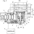
- the electric brake device includes: a housing 1; an electric motor 2; a speed reduction mechanism 3 configured to reduce a speed of rotation of the electric motor 2; a linear motion mechanism 4; a locking mechanism 5; a brake rotor 6; a brake pad 7; and a controller 9 ( Fig. 3 ).
- a base plate 8 is provided at an opening end of the housing 1 so as to extend radially outward, and the electric motor 2 is supported by the base plate 8.
- the linear motion mechanism 4 is incorporated into the housing 1 so as to apply a braking force to the brake rotor 6, in this example, to a disc rotor 6 by output from the electric motor 2.
- the opening end of the housing 1 and an outer side surface of the base plate 8 are covered by a cover 10.
- the linear motion mechanism 4 is a mechanism that converts a rotary motion outputted from the speed reduction mechanism 3 into a linear motion and brings the brake pad 7 into contact with the brake rotor 6 or separates the brake pad 7 from the brake rotor 6.
- the linear motion mechanism 4 includes a slide member 11, a bearing member 12, an annular thrust plate 13, a thrust bearing 14, rolling bearings 15, 15, a rotation shaft 16, a carrier 17, and slide bearings 18, 19.
- the cylindrical slide member 11 is supported on the inner circumferential surface of the housing 1 such that the slide member 11 is prevented from rotating and is movable in the axial direction.
- a helical projection 11a is helically formed so as to project by a predetermined distance in the radially inward direction.
- a plurality of planetary rollers 20 described below mesh with the helical projection 11a.
- the bearing member 12 is provided at one end side, in the axial direction, of the slide member 11 in the housing 1.
- the bearing member 12 includes: a flange portion that extends radially outward; and a boss portion.
- the rolling bearings 15, 15 are fitted in the boss portion, and the rotation shaft 16 is fitted into the inner diameter surface of an inner ring of each of the bearings 15, 15. Therefore, the rotation shaft 16 is rotatably supported by the bearing member 12 through the bearings 15, 15.
- the carrier 17 is provided on the inner circumference of the slide member 11 so as to be rotatable about the rotation shaft 16.
- the carrier 17 has disks 17a, 17b that oppose each other in the axial direction.
- the disk 17b on the bearing member 12 side may be referred to as an inner disk 17b, and the disk 17a may be referred to as an outer disk 17a.
- a distance adjustment member 17c is provided, in the disk 17a that is one of the disks, on the side surface opposing the disk 17b that is the other of the disks, so as to project in the axial direction from the outer circumferential edge portion of the side surface.
- a plurality of the distance adjustment members 17c are arranged so as to be spaced from each other in the circumferential direction such that distances between the plurality of planetary rollers 20 are adjusted. Both the disks 17a and 17b are integrated with each other through the distance adjustment members 17c.
- the inner disk 17b is supported by the slide bearing 18 that is fitted between the inner disk 17b and the rotation shaft 16 so as to be movable in the axial direction and rotatable.
- the outer disk 17a has a shaft insertion hole formed at the center thereof and the slide bearing 19 is fitted into the shaft insertion hole.
- the outer disk 17a is rotatably supported through the slide bearing 19 by the rotation shaft 16.
- a washer for receiving thrust load is fitted to the end portion of the rotation shaft 16, and a retaining ring that prevents the washer from being removed is provided.
- the carrier 17 has a plurality of roller shafts 21 spaced from each other in the circumferential direction. Both end portions of each roller shaft 21 are supported by and between the disks 17a and 17b. That is, each of the disks 17a and 17b has a plurality of shaft insertion holes that are formed as long holes, and both the end portions of each roller shaft 21 are inserted into the corresponding shaft insertion holes, whereby the roller shafts 21 are supported so as to be movable in the radial direction.
- An elastic ring 22 is extended over the plurality of roller shafts 21 so as to urge the roller shafts 21 in the radially inward direction.
- the planetary rollers 20 are rotatably supported by the roller shafts 21, respectively, and each planetary roller 20 is disposed between the outer circumferential surface of the rotation shaft 16 and the inner circumferential surface of the slide member 11.
- Each planetary roller 20 is pressed against the outer circumferential surface of the rotation shaft 16 by urging force of the elastic ring 22 extended over the plurality of roller shafts 21.
- each planetary roller 20 that is in contact with the outer circumferential surface of the rotation shaft 16 rotates due to contact friction.
- a washer and a thrust bearing are disposed between the inner disk 17b of the carrier 17 and one end portion, in the axial direction, of each planetary roller 20.
- the annular thrust plate 13 and the thrust bearing 14 are disposed between the inner disk 17b and the bearing member 12.
- the speed reduction mechanism 3 is a mechanism that reduces a speed of rotation of the electric motor 2 and transmits the reduced rotation to an output gear 23 fixed to the rotation shaft 16, and the speed reduction mechanism 3 includes a plurality of gear trains.
- the speed reduction mechanism 3 sequentially reduces, by gear trains 25, 26, and 27, a speed of rotation of an input gear 24 mounted to a rotor shaft 2a of the electric motor 2, and allows the rotation to be transmitted to the output gear 23 fixed to the end portion of the rotation shaft 16.
- the locking mechanism 5 will be described.
- the locking mechanism 5 is configured to switch between: a locking state in which a braking force reducing operation of the linear motion mechanism 4 is inhibited; and an unlocking state in which the braking force reducing operation is allowed.
- the locking mechanism 5 is provided in the speed reduction mechanism 3.
- the locking mechanism 5 has: a casing (not shown); a lock pin 29; a bias mechanism (not shown) that biases the lock pin 29 so as to be in the unlocking state; and a linear solenoid 30 that acts as an actuator for driving switching of the lock pin 29.
- the casing is supported by the base plate 8, and the base plate 8 has a pin hole through which the lock pin 29 is allowed to move forward and backward.
- the locking state is obtained when the lock pin 29 is moved forward by the linear solenoid 30, and engaged into a locking hole (not shown) formed in an intermediate gear 28 on the output side of the gear train 26, to prevent rotation of the intermediate gear 28. Meanwhile, by the linear solenoid 30 being made off, the lock pin 29 is retracted in the casing so as to be removed from the locking hole by the bias force from the bias mechanism, to allow rotation of the intermediate gear 28, whereby the locking mechanism 5 enters the unlocking state.
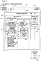
- Fig. 3 is a block diagram illustrating a control system of the electric brake device.
- a vehicle having the electric brake device mounted therein includes an ECU 31 that is an electric control unit that controls the entirety of the vehicle.
- the ECU 31 generates a speed reduction command in accordance with an output from a brake command device 40.
- the brake command device 40 includes: a brake pedal 32; and a stroke sensor 32a that detects the stroke, which depends on the amount of operation (stroke amount) of the brake pedal 32.
- An inverter device 33 is connected to the ECU 31, and the inverter device 33 includes: a power circuit section 34 provided for each electric motor 2; and a motor control unit 35 that controls the power circuit section 34.
- the motor control unit 35 includes a computer, a program executed by the computer, and an electronic circuit.
- the motor control unit 35 converts, in accordance with a speed reduction command received from the ECU 31, the speed reduction command into a current command, and sends the current command to a PWM control section 34a of the power circuit section 34.
- the motor control unit 35 has a function of outputting, to the ECU 31, various information such as detected values and control values concerning the electric motor 2.
- the power circuit section 34 has: an inverter 34b that converts DC power from a power supply 36 into three-phase AC power used for driving the electric motor 2; and the PWM control section 34a that controls the inverter 34b.
- the electric motor 2 may include a surface-magnet-type motor in which a magnet is provided on the surface of the rotor, i.e., a so-called SPM (Surface Permanent Magnet Motor), and is formed as a three-phase synchronous motor.
- the inverter 34b is formed by a plurality of semiconductor switching elements (not shown), and the PWM control section 34a performs pulse width modulation of the inputted current command to send an on/off command to each semiconductor switching element.
- the motor control unit 35 has a motor driving control section 37 as its basic control section.
- the motor driving control section 37 converts, in accordance with a speed reduction command indicated by a torque command received from the ECU 31 that is a higher-order or master control unit, the speed reduction command into a current command, and sends the current command to the PWM control section 34a of the power circuit section 34.
- the motor driving control section 37 obtains, from a current detection device 38, a value of a motor current that flows from the inverter 34b to the electric motor 2 to perform current feedback control.
- the motor driving control section 37 obtains a rotation angle of a rotor of the electric motor 2 from a rotation angle sensor 39, and sends a current command to the PWM control section 34a so as to enable efficient motor driving according to the rotor rotation angle.
- the motor control unit 35 above described includes an emergency braking detection module 41, a flux weakening control module 42, a braking force estimation module 43, and an emergency braking request cancellation module 44.
- the emergency braking detection module 41 is configured to detect an emergency braking request and includes a determination section 41a.
- the emergency braking detection module 41 holds a threshold for a differential value dFT/dt of an input value from the brake command device 40.
- the determination section 41a determines that the dFT/dt has exceeded the threshold
- the emergency braking detection module 41 detects an emergency braking request.
- the motor control unit 35 includes a storage unit 45 such as a ROM, and the storage unit 45 is electrically connected to each component in the inverter device.
- the threshold is stored in the storage unit 45 in a rewritable manner. The threshold may be determined through a test with an actual vehicle or simulation.
- the flux weakening control module 42 is activated so that flux weakening control is performed by applying a d-axis current to the electric motor 2. Accordingly, it is possible to increase the rotational frequency of the electric motor 2 to enhance the followability to the braking force command.
- a steady state control section 46 is activated instead of the flux weakening control module 42.
- the steady state control section 46 controls the motor current under an efficient current condition that makes the d-axis current zero, for example. Accordingly, power consumption during steady operation can be reduced.
- the d-axis and q-axis currents of the electric motor 2 in the emergency braking state where the emergency braking request is detected may be determined based on a mapping table of rotational frequency vs. torque characteristic in which the relationship between the rotational frequency and the torque of the electric motor 2 is defined.
- a desired mapping table of rotational frequency vs. torque characteristic for the emergency braking state is stored.
- the mapping table of rotational frequency vs. torque characteristic may be defined through a test with an actual vehicle or simulation.
- the braking force estimation module 43 estimates a real braking force ("actual braking force") based on the current detected by the current detection device 38, for example.
- the storage unit 45 stores a table in which the relationship between the actual braking force and the current flowing in the electric motor 2 is defined.
- the braking force estimation module 43 estimates the actual braking force by looking up the detected current value on the table in which the relationship is defined.
- the emergency braking request cancellation module 44 cancels or invalidates the emergency braking request. This is because, if the deviation between the input value from the brake command device 40 and the estimated braking force value is less than or equal to the certain value, it can be considered that the speed reduction is not caused by emergency braking but by normal breaking. Accordingly, the flux weakening control module 42 is replaced by the steady state control section 46, and then, the steady state control section 46 controls the motor current.
- Fig. 4 is a schematic diagram showing an example in which the electric brake device is mounted on a four-wheeled vehicle 47.
- the electric motor 2 is provided to each wheel 48.
- Each electric motor 2 is drive-controlled so as to press the brake pad 7 ( Fig. 1 ) against the corresponding brake rotor 6 ( Fig. 1 ) in the associated wheel 48.
- This embodiment shows an example in which the brake pedal 32 and the stroke sensor 32a which measures the stroke amount of the brake pedal 32 are used as the brake command device 40.
- the present invention is not limited to this example. Another example will be described later.
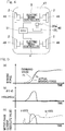
- Fig. 5 shows the outline of the flux weakening control performed in the electric brake device.
- Graph (a) of Fig. 5 shows how the value FT of the braking force command and the actual braking force Fb over time.
- Graph (b) of Fig. 5 shows the differential value dFT/dt of the value FT of the braking force command shown in graph (a) of Fig. 5 .
- Graph (c) of Fig. 5 shows d-axis and q-axis currents of the electric motor.
- the differential value dFT/dt of the value FT of the braking force command exceeds the threshold, the d-axis current is applied to the electric motor as shown in graph (c) of Fig.
- the d-axis and q-axis currents may be determined in advance, based on the upper limit value for current to be applied to the electric motor, and the output characteristics of the rotational frequency and the torque of the electric motor which are defined in the mapping table of rotational frequency vs. torque characteristic ( Fig. 3 ).
- Fig. 6 is a flow chart showing a method for controlling the electric brake device step by step. The following explanation will be made also with reference to Fig. 3 .
- This calculation process is started during operation of a vehicle, and the emergency braking detection module 41 obtains a braking force command (step S1).
- step S2 the determination section 41a determines whether dFT/dt has exceeded the threshold.
- step S3 the steady state control section 46 sets the d-axis current to zero so as to control the motor current only based on the q-axis current (step S3). Then, the process goes to step S7.
- the flux weakening control module 42 obtains a desired motor rotational frequency ⁇ from the mapping table of rotational frequency vs. torque characteristic (step S4). Next, the flux weakening control module 42 determines d-axis and q-axis currents that maximize the output of the electric motor 2 (step S5), and determines a value of a brake command Ft' (step S6) at the emergency braking. The value Ft' of the brake command at the emergency braking is greater than the value FT from the brake command device 40. Next, the value Ft' of the brake command at the emergency braking is converted into a current command, and then, in step S7, the motor driving control section 37 sends the current command to the PWM control section 34a. Then, this calculation process is ended.
- the controller 9 performs drive control on the electric motor 2 such that the brake pad 7 having a predetermined clearance from the brake rotor 6, is pressed against the brake rotor 6 when the value of the braking force command from the brake command device 40 increases.
- the flux weakening control module 42 of the controller 9 applies a d-axis current to the electric motor 2 to perform flux weakening control, thereby increasing the rotational frequency of the electric motor 2 to enhance the followability to the braking force command.
- the appropriate pair of values of d-axis and q-axis currents differs according to which is emphasized, where or efficiency.
- d-axis current fails to generate the torque, that is, d-axis current makes only copper loss.
- the value of the d-axis current is set to zero.
- the flux weakening control module 42 applies a d-axis current to the electric motor 2 to perform flux weakening control.
- Using the differential value allows compensation operation that applies a strong braking force when an emergency braking request is detected, even if the force applied on the brake pedal is insufficient, for example.
- the emergency braking request cancellation module 44 cancels the emergency braking request. Since the emergency braking request can be canceled without delay, power consumption during steady operation can be further reduced.
- the flux weakening control module 42 uses a value of the command greater than the value of the command from the brake command device 40. By increasing the value of the command from the brake command device 40 when an emergency braking request is detected, a braking force larger than that in the steady state can be easily applied.
- Fig. 7 shows another embodiment in which, in addition to the configuration shown in Fig. 4 , the vehicle 47 has a distance detection device 49 that detects the distance between the vehicle 47 and an obstacle outside the vehicle.
- the distance detection device 49 may include a millimeter wave radar and a camera.
- the emergency braking detection module 41 ( Fig. 3 ) detects an emergency braking request based on the distance between the vehicle and the obstacle detected by the distance detection device 49, or based on the differential value of the distance. For example, in a state where the relative distance between the vehicle 47 and the obstacle or the differential value of the distance becomes less than or equal to a certain value, when the brake command device 40 sends a braking force command to the controller 9, an emergency braking state can be determined.
- the flux weakening control module 42 may have an emergency braking level estimation section 42a and a current limitation section 42b.
- the emergency braking level estimation section 42a estimates the level of the emergency when an emergency braking request is detected. For example, the emergency braking level estimation section 42a estimates the level of the emergency, based on the speed of operating the brake pedal 32, that is, the differential value dFT/dt of the stroke amount measured by the stroke sensor 32a. If the differential value dFT/dt exceeds a threshold and becomes greater than the threshold, the higher the level of the emergency is estimated.
- the current limitation section 42b determines an upper limit value for the d-axis current to be used in the flux weakening control, depending on the estimated level of the emergency For example, the higher the estimated level of the emergency, the higher the upper limit value for the d-axis current is determined. In this manner, by determining the upper limit value for the d-axis current to be used in the flux weakening control depending on the level of the emergency braking state, it is possible to finely control the output of the electric motor 2.
- the ECU 31 may include a power supply monitoring section 50 that measures the remaining amount of the power of the power supply 36.
- the flux weakening control module 42 ( Fig. 3 ) may limit the d-axis current to be used in the flux weakening control when the power remaining amount measured by the power supply monitoring section 50 becomes less than or equal to a threshold.
- the power supply monitoring section 50 may be provided in any component other than the ECU.
- an emergency braking request is detected based on comparison between the differential value of the input value from the brake command device 40 and a threshold.
- a threshold may be set for the input value from the brake command device 40, and the emergency braking detection module 41 may detect an emergency braking request through comparison between the input value and the threshold.
- a threshold may be set for the deviation between the input value from the brake command device 40 and the estimated braking force value estimated by the braking force estimation module 43, and the emergency braking detection module 41 may detect an emergency braking request through comparison between the deviation and the respective threshold therefor.
- an emergency braking request may be detected through comparison between a differential value of the deviation and a respective threshold therefor.
- the flux weakening control module 42 may temporarily make greater the upper limit value for the current to be applied to the electric motor 2, than that in the steady state where the emergency braking request is not detected. In this case, a braking force larger than that in the steady state can be applied at the time of an emergency braking request, and thus, the braking distance can be shortened.
- the vehicle may include a load sensor that detects the braking force by means of load and feedback control of the load detected by the load sensor may be used.
- the electric motor may be an IPM (Interior Permanent Magnet Motor) in which a magnet is embedded in the rotor.
- IPM Interior Permanent Magnet Motor
- a d-axis current may be determined so as to maximize a torque including a reluctance torque.
- the d-axis current is determined in consideration of the reluctance torque caused by magnetization of the rotor and the torque caused by magnetization of the magnet inside the rotor, and thus, the output of the electric motor can be further finely controlled.
- the electric motor may be a surface magnet brushless DC motor.
- the electric brake device is applied to a disc brake.
- the application is not limited to application to a disc brake only.
- the electric brake device may be applied to a drum brake.
Landscapes
- Engineering & Computer Science (AREA)
- Power Engineering (AREA)
- Mechanical Engineering (AREA)
- General Engineering & Computer Science (AREA)
- Transportation (AREA)
- Control Of Ac Motors In General (AREA)
- Braking Systems And Boosters (AREA)
- Braking Arrangements (AREA)
- Regulating Braking Force (AREA)
- Electric Propulsion And Braking For Vehicles (AREA)
Claims (9)
- Dispositif formant frein électrique comprenant :un rotor de frein (6) ;une plaquette de frein (7) ;un moteur électrique (2) ;un mécanisme de mouvement linéaire (4) configuré pour convertir un mouvement rotatif du moteur électrique (2) en un mouvement linéaire qui est transmis à la plaquette de frein (7) ;un contrôleur (9) configuré pour commander le moteur électrique (2) ; caractérisé parun dispositif de commande de frein (40) configuré pour envoyer une commande de force de freinage au contrôleur (9), dans lequel le contrôleur (9) comprend :un module de détection de freinage d'urgence (41) configuré pour détecter une demande de freinage d'urgence ;une section de commande d'état stable (46) configurée pour effectuer un freinage dans un état stable ; etun module de commande d'affaiblissement de flux (42) configuré pour effectuer une commande d'affaiblissement de flux, la commande d'affaiblissement de flux (42) étant exécutée lorsque le module de détection de freinage d'urgence détecte une demande de freinage d'urgence.
- Dispositif formant frein électrique selon la revendication 1, comprenant en outre :un module d'estimation de force de freinage (43) configuré pour estimer la force de freinage, dans lequelun/des seuil(s) respectifs) est/sont déterminé(s) pour au moins l'une des valeurs suivantes : une valeur d'entrée du dispositif de commande de frein (40) ; une valeur différentielle de la valeur d'entrée ; un écart entre la valeur d'entrée du dispositif de commande de frein (40) et la force de freinage estimée par le module d'estimation de force de freinage (43) ; et une valeur différentielle de l'écart, etle module de détection de freinage d'urgence (41) détecte la demande de freinage d'urgence par comparaison entre la valeur et le seuil respectif correspondant.
- Dispositif formant frein électrique selon la revendication 1, dans lequel
un véhicule (47) sur lequel est monté le dispositif formant frein électrique comprend un dispositif de détection de distance (49) configuré pour détecter une distance entre le véhicule et un obstacle à l'extérieur du véhicule, et le module de détection de freinage d'urgence (41) détecte la demande de freinage d'urgence sur la base de la distance détectée par le dispositif de détection de distance (49) ou une valeur différentielle de la distance. - Dispositif formant frein électrique selon l'une quelconque des revendications 1 à 3, dans lequel
le module de commande d'affaiblissement de flux (42) comprend :une section d'estimation de niveau de freinage d'urgence (42a) configurée pour estimer un niveau d'un état de freinage d'urgence, le niveau étant estimé lorsque la demande de freinage d'urgence est détectée ; etune section de limitation de courant (42b) configurée pour déterminer une valeur limite supérieure pour un courant d'axe-d à utiliser dans la commande d'affaiblissement de flux, en fonction du niveau de l'état de freinage d'urgence estimé par la section d'estimation de niveau de freinage d'urgence (42a). - Dispositif formant frein électrique selon l'une quelconque des revendications 1 à 4, comprenant en outre :un module d'estimation de force de freinage (43) configuré pour estimer la force de freinage, dans lequelle contrôleur (9) comprend un module d'annulation de demande de freinage d'urgence (44) configuré pour annuler la demande de freinage d'urgence, la demande de freinage d'urgence étant annulée lorsqu'un écart entre une valeur d'entrée du dispositif de commande de frein (40) et la force de freinage estimée par le module d'estimation de force de freinage (43) devient inférieur ou égal à une certaine valeur.
- Dispositif formant frein électrique selon l'une quelconque des revendications 1 à 5, dans lequel
lorsque la demande de freinage d'urgence est détectée, le module de commande d'affaiblissement du flux (42) augmente temporairement une valeur limite supérieure pour un courant à appliquer au moteur électrique (2), par rapport à celle correspondant à l'état stationnaire où aucune demande de freinage d'urgence n'est détectée. - Dispositif formant frein électrique selon l'une quelconque des revendications 1 à 6, comprenant en outre :une section de surveillance d'alimentation électrique (50) configurée pour mesurer une quantité d'énergie restante d'une alimentation électrique qui entraîne le moteur électrique (2), dans laquellele module de commande d'affaiblissement de flux (42) limite un courant d'axe-d à utiliser dans la commande d'affaiblissement de flux lorsque la quantité d'énergie restante mesurée par la section de surveillance d'alimentation devient inférieure ou égale à un seuil.
- Dispositif de frein électrique selon l'une quelconque des revendications 1 à 7, dans lequel
lorsque la demande de freinage d'urgence est détectée, le module de commande d'affaiblissement de flux (42) détermine une valeur de la commande de freinage d'urgence de manière à être supérieure à une valeur à partir de la commande du dispositif de commande de freinage (40). - Dispositif formant frein électrique selon l'une quelconque des revendications 1 à 8, dans lequel
le moteur électrique (2) est un moteur à courant continu sans balais à aimants permanents montés sur la surface.
Applications Claiming Priority (2)
| Application Number | Priority Date | Filing Date | Title |
|---|---|---|---|
| JP2013186046A JP6275979B2 (ja) | 2013-09-09 | 2013-09-09 | 電動ブレーキ装置 |
| PCT/JP2014/072908 WO2015033885A1 (fr) | 2013-09-09 | 2014-09-01 | Dispositif de frein électrique |
Publications (3)
| Publication Number | Publication Date |
|---|---|
| EP3045359A1 EP3045359A1 (fr) | 2016-07-20 |
| EP3045359A4 EP3045359A4 (fr) | 2017-06-21 |
| EP3045359B1 true EP3045359B1 (fr) | 2018-06-27 |
Family
ID=52628359
Family Applications (1)
| Application Number | Title | Priority Date | Filing Date |
|---|---|---|---|
| EP14842713.1A Not-in-force EP3045359B1 (fr) | 2013-09-09 | 2014-09-01 | Dispositif de frein électrique |
Country Status (5)
| Country | Link |
|---|---|
| US (1) | US9856936B2 (fr) |
| EP (1) | EP3045359B1 (fr) |
| JP (1) | JP6275979B2 (fr) |
| CN (1) | CN105517862B (fr) |
| WO (1) | WO2015033885A1 (fr) |
Families Citing this family (12)
| Publication number | Priority date | Publication date | Assignee | Title |
|---|---|---|---|---|
| JP6373715B2 (ja) * | 2014-10-16 | 2018-08-15 | Ntn株式会社 | 電動ブレーキ装置 |
| GB201513549D0 (en) * | 2015-07-31 | 2015-09-16 | Siemens Ag | Inverter |
| JP6664903B2 (ja) * | 2015-08-11 | 2020-03-13 | Ntn株式会社 | 電動ブレーキ装置 |
| JP6644502B2 (ja) * | 2015-09-10 | 2020-02-12 | Ntn株式会社 | 電動ブレーキ装置 |
| JP2018070083A (ja) * | 2016-11-04 | 2018-05-10 | Ntn株式会社 | 電動ブレーキ装置 |
| JP6986903B2 (ja) * | 2017-08-25 | 2021-12-22 | Ntn株式会社 | 電動式直動アクチュエータおよび電動ブレーキ装置 |
| JP7211306B2 (ja) * | 2019-08-27 | 2023-01-24 | 株式会社デンソー | モータ駆動装置 |
| JP6987197B1 (ja) * | 2020-09-07 | 2021-12-22 | 三菱電機株式会社 | 電動ブレーキの制御装置 |
| JP7606356B2 (ja) * | 2021-02-02 | 2024-12-25 | ナブテスコ株式会社 | 鉄道車両用ブレーキ制御装置、鉄道車両用ブレーキ装置 |
| JP7707909B2 (ja) * | 2021-12-27 | 2025-07-15 | コベルコ建機株式会社 | ブレーキ制御装置及びこれを備えたクレーン |
| US12365325B2 (en) * | 2023-03-13 | 2025-07-22 | GM Global Technology Operations LLC | Brake actuator control systems and methods |
| US20250340127A1 (en) * | 2024-05-06 | 2025-11-06 | Caterpillar Inc. | Motor fluxing activation |
Family Cites Families (14)
| Publication number | Priority date | Publication date | Assignee | Title |
|---|---|---|---|---|
| US4568863A (en) * | 1984-06-27 | 1986-02-04 | Goodyear Aerospace Corporation | Controller for electric brake motors |
| JPH03169291A (ja) | 1989-11-25 | 1991-07-22 | Hitachi Ltd | 誘導電動機の制御装置 |
| JPH06206527A (ja) * | 1992-04-08 | 1994-07-26 | Nippon Denshi Kogyo Kk | 車両の緊急制動装置 |
| JP2000203402A (ja) * | 1999-01-19 | 2000-07-25 | Toyota Motor Corp | 制動制御装置 |
| JP4346001B2 (ja) * | 2000-08-24 | 2009-10-14 | ボッシュ株式会社 | 電気自動車の制動装置 |
| JP2002171796A (ja) * | 2000-09-19 | 2002-06-14 | Denso Corp | 電動ブレーキ装置 |
| JP3797481B2 (ja) | 2002-05-24 | 2006-07-19 | 日信工業株式会社 | 電気式ディスクブレーキ |
| DE10234848A1 (de) * | 2002-07-31 | 2004-02-19 | Robert Bosch Gmbh | Elektromechanische Bremse |
| JP4898123B2 (ja) | 2005-01-13 | 2012-03-14 | Ntn株式会社 | 電動式直動アクチュエータおよび電動式ブレーキ装置 |
| JP4902373B2 (ja) * | 2007-01-30 | 2012-03-21 | 本田技研工業株式会社 | ブレーキ装置およびブレーキ装置の制御方法 |
| JP5376279B2 (ja) * | 2008-02-20 | 2013-12-25 | Ntn株式会社 | 電動式直動アクチュエータおよび電動式ブレーキ装置 |
| DE102010049091A1 (de) * | 2010-10-21 | 2012-04-26 | Gm Global Technology Operations Llc (N.D.Ges.D. Staates Delaware) | Verfahren zum Betreiben zumindest eines Sensors eines Fahrzeugs und Fahrzeug mit zumindest einem Sensor |
| JP5367683B2 (ja) * | 2010-12-20 | 2013-12-11 | 本田技研工業株式会社 | 車両用ブレーキ装置 |
| US8896244B2 (en) * | 2011-12-15 | 2014-11-25 | Steering Solutions Ip Holding Corporation | Motor control system for limiting regenerative current |
-
2013
- 2013-09-09 JP JP2013186046A patent/JP6275979B2/ja not_active Expired - Fee Related
-
2014
- 2014-09-01 WO PCT/JP2014/072908 patent/WO2015033885A1/fr not_active Ceased
- 2014-09-01 CN CN201480049205.7A patent/CN105517862B/zh not_active Expired - Fee Related
- 2014-09-01 EP EP14842713.1A patent/EP3045359B1/fr not_active Not-in-force
-
2016
- 2016-03-01 US US15/057,389 patent/US9856936B2/en not_active Expired - Fee Related
Non-Patent Citations (1)
| Title |
|---|
| None * |
Also Published As
| Publication number | Publication date |
|---|---|
| JP2015051729A (ja) | 2015-03-19 |
| US9856936B2 (en) | 2018-01-02 |
| CN105517862A (zh) | 2016-04-20 |
| US20160178021A1 (en) | 2016-06-23 |
| CN105517862B (zh) | 2018-01-30 |
| WO2015033885A1 (fr) | 2015-03-12 |
| EP3045359A1 (fr) | 2016-07-20 |
| JP6275979B2 (ja) | 2018-02-07 |
| EP3045359A4 (fr) | 2017-06-21 |
Similar Documents
| Publication | Publication Date | Title |
|---|---|---|
| EP3045359B1 (fr) | Dispositif de frein électrique | |
| US10125834B2 (en) | Electric brake device and electric brake device system | |
| US10352383B2 (en) | Electric brake device | |
| EP3042814B1 (fr) | Dispositif de frein électrique | |
| EP3042813B1 (fr) | Dispositif de frein électrique | |
| EP3147167B1 (fr) | Dispositif de frein électrique | |
| US9709112B2 (en) | Electric brake device | |
| US9994204B2 (en) | Vehicular brake system | |
| US10377355B2 (en) | Electric brake device | |
| US11441626B2 (en) | Electric linear actuator and electric brake device | |
| JP6258053B2 (ja) | 電動ブレーキ装置 | |
| JP2019024315A (ja) | モータ駆動装置 |
Legal Events
| Date | Code | Title | Description |
|---|---|---|---|
| PUAI | Public reference made under article 153(3) epc to a published international application that has entered the european phase |
Free format text: ORIGINAL CODE: 0009012 |
|
| 17P | Request for examination filed |
Effective date: 20160318 |
|
| AK | Designated contracting states |
Kind code of ref document: A1 Designated state(s): AL AT BE BG CH CY CZ DE DK EE ES FI FR GB GR HR HU IE IS IT LI LT LU LV MC MK MT NL NO PL PT RO RS SE SI SK SM TR |
|
| AX | Request for extension of the european patent |
Extension state: BA ME |
|
| DAX | Request for extension of the european patent (deleted) | ||
| A4 | Supplementary search report drawn up and despatched |
Effective date: 20170522 |
|
| RIC1 | Information provided on ipc code assigned before grant |
Ipc: B60T 8/17 20060101AFI20170516BHEP Ipc: H02P 21/00 20160101ALI20170516BHEP Ipc: B60T 13/74 20060101ALI20170516BHEP Ipc: H02P 15/00 20060101ALI20170516BHEP Ipc: H02P 27/04 20160101ALI20170516BHEP Ipc: H02K 7/106 20060101ALI20170516BHEP |
|
| GRAP | Despatch of communication of intention to grant a patent |
Free format text: ORIGINAL CODE: EPIDOSNIGR1 |
|
| INTG | Intention to grant announced |
Effective date: 20180209 |
|
| GRAS | Grant fee paid |
Free format text: ORIGINAL CODE: EPIDOSNIGR3 |
|
| GRAA | (expected) grant |
Free format text: ORIGINAL CODE: 0009210 |
|
| AK | Designated contracting states |
Kind code of ref document: B1 Designated state(s): AL AT BE BG CH CY CZ DE DK EE ES FI FR GB GR HR HU IE IS IT LI LT LU LV MC MK MT NL NO PL PT RO RS SE SI SK SM TR |
|
| REG | Reference to a national code |
Ref country code: GB Ref legal event code: FG4D |
|
| REG | Reference to a national code |
Ref country code: AT Ref legal event code: REF Ref document number: 1012019 Country of ref document: AT Kind code of ref document: T Effective date: 20180715 |
|
| REG | Reference to a national code |
Ref country code: IE Ref legal event code: FG4D |
|
| REG | Reference to a national code |
Ref country code: DE Ref legal event code: R096 Ref document number: 602014027677 Country of ref document: DE |
|
| REG | Reference to a national code |
Ref country code: FR Ref legal event code: PLFP Year of fee payment: 5 |
|
| PG25 | Lapsed in a contracting state [announced via postgrant information from national office to epo] |
Ref country code: NO Free format text: LAPSE BECAUSE OF FAILURE TO SUBMIT A TRANSLATION OF THE DESCRIPTION OR TO PAY THE FEE WITHIN THE PRESCRIBED TIME-LIMIT Effective date: 20180927 Ref country code: LT Free format text: LAPSE BECAUSE OF FAILURE TO SUBMIT A TRANSLATION OF THE DESCRIPTION OR TO PAY THE FEE WITHIN THE PRESCRIBED TIME-LIMIT Effective date: 20180627 Ref country code: SE Free format text: LAPSE BECAUSE OF FAILURE TO SUBMIT A TRANSLATION OF THE DESCRIPTION OR TO PAY THE FEE WITHIN THE PRESCRIBED TIME-LIMIT Effective date: 20180627 Ref country code: FI Free format text: LAPSE BECAUSE OF FAILURE TO SUBMIT A TRANSLATION OF THE DESCRIPTION OR TO PAY THE FEE WITHIN THE PRESCRIBED TIME-LIMIT Effective date: 20180627 Ref country code: BG Free format text: LAPSE BECAUSE OF FAILURE TO SUBMIT A TRANSLATION OF THE DESCRIPTION OR TO PAY THE FEE WITHIN THE PRESCRIBED TIME-LIMIT Effective date: 20180927 |
|
| REG | Reference to a national code |
Ref country code: NL Ref legal event code: MP Effective date: 20180627 |
|
| REG | Reference to a national code |
Ref country code: LT Ref legal event code: MG4D |
|
| PG25 | Lapsed in a contracting state [announced via postgrant information from national office to epo] |
Ref country code: HR Free format text: LAPSE BECAUSE OF FAILURE TO SUBMIT A TRANSLATION OF THE DESCRIPTION OR TO PAY THE FEE WITHIN THE PRESCRIBED TIME-LIMIT Effective date: 20180627 Ref country code: RS Free format text: LAPSE BECAUSE OF FAILURE TO SUBMIT A TRANSLATION OF THE DESCRIPTION OR TO PAY THE FEE WITHIN THE PRESCRIBED TIME-LIMIT Effective date: 20180627 Ref country code: LV Free format text: LAPSE BECAUSE OF FAILURE TO SUBMIT A TRANSLATION OF THE DESCRIPTION OR TO PAY THE FEE WITHIN THE PRESCRIBED TIME-LIMIT Effective date: 20180627 Ref country code: GR Free format text: LAPSE BECAUSE OF FAILURE TO SUBMIT A TRANSLATION OF THE DESCRIPTION OR TO PAY THE FEE WITHIN THE PRESCRIBED TIME-LIMIT Effective date: 20180928 |
|
| REG | Reference to a national code |
Ref country code: AT Ref legal event code: MK05 Ref document number: 1012019 Country of ref document: AT Kind code of ref document: T Effective date: 20180627 |
|
| PG25 | Lapsed in a contracting state [announced via postgrant information from national office to epo] |
Ref country code: NL Free format text: LAPSE BECAUSE OF FAILURE TO SUBMIT A TRANSLATION OF THE DESCRIPTION OR TO PAY THE FEE WITHIN THE PRESCRIBED TIME-LIMIT Effective date: 20180627 |
|
| PG25 | Lapsed in a contracting state [announced via postgrant information from national office to epo] |
Ref country code: PL Free format text: LAPSE BECAUSE OF FAILURE TO SUBMIT A TRANSLATION OF THE DESCRIPTION OR TO PAY THE FEE WITHIN THE PRESCRIBED TIME-LIMIT Effective date: 20180627 Ref country code: IS Free format text: LAPSE BECAUSE OF FAILURE TO SUBMIT A TRANSLATION OF THE DESCRIPTION OR TO PAY THE FEE WITHIN THE PRESCRIBED TIME-LIMIT Effective date: 20181027 Ref country code: EE Free format text: LAPSE BECAUSE OF FAILURE TO SUBMIT A TRANSLATION OF THE DESCRIPTION OR TO PAY THE FEE WITHIN THE PRESCRIBED TIME-LIMIT Effective date: 20180627 Ref country code: SK Free format text: LAPSE BECAUSE OF FAILURE TO SUBMIT A TRANSLATION OF THE DESCRIPTION OR TO PAY THE FEE WITHIN THE PRESCRIBED TIME-LIMIT Effective date: 20180627 Ref country code: AT Free format text: LAPSE BECAUSE OF FAILURE TO SUBMIT A TRANSLATION OF THE DESCRIPTION OR TO PAY THE FEE WITHIN THE PRESCRIBED TIME-LIMIT Effective date: 20180627 Ref country code: RO Free format text: LAPSE BECAUSE OF FAILURE TO SUBMIT A TRANSLATION OF THE DESCRIPTION OR TO PAY THE FEE WITHIN THE PRESCRIBED TIME-LIMIT Effective date: 20180627 Ref country code: CZ Free format text: LAPSE BECAUSE OF FAILURE TO SUBMIT A TRANSLATION OF THE DESCRIPTION OR TO PAY THE FEE WITHIN THE PRESCRIBED TIME-LIMIT Effective date: 20180627 |
|
| PG25 | Lapsed in a contracting state [announced via postgrant information from national office to epo] |
Ref country code: SM Free format text: LAPSE BECAUSE OF FAILURE TO SUBMIT A TRANSLATION OF THE DESCRIPTION OR TO PAY THE FEE WITHIN THE PRESCRIBED TIME-LIMIT Effective date: 20180627 Ref country code: ES Free format text: LAPSE BECAUSE OF FAILURE TO SUBMIT A TRANSLATION OF THE DESCRIPTION OR TO PAY THE FEE WITHIN THE PRESCRIBED TIME-LIMIT Effective date: 20180627 Ref country code: IT Free format text: LAPSE BECAUSE OF FAILURE TO SUBMIT A TRANSLATION OF THE DESCRIPTION OR TO PAY THE FEE WITHIN THE PRESCRIBED TIME-LIMIT Effective date: 20180627 |
|
| REG | Reference to a national code |
Ref country code: DE Ref legal event code: R097 Ref document number: 602014027677 Country of ref document: DE |
|
| PG25 | Lapsed in a contracting state [announced via postgrant information from national office to epo] |
Ref country code: MC Free format text: LAPSE BECAUSE OF FAILURE TO SUBMIT A TRANSLATION OF THE DESCRIPTION OR TO PAY THE FEE WITHIN THE PRESCRIBED TIME-LIMIT Effective date: 20180627 |
|
| REG | Reference to a national code |
Ref country code: CH Ref legal event code: PL |
|
| PLBE | No opposition filed within time limit |
Free format text: ORIGINAL CODE: 0009261 |
|
| STAA | Information on the status of an ep patent application or granted ep patent |
Free format text: STATUS: NO OPPOSITION FILED WITHIN TIME LIMIT |
|
| GBPC | Gb: european patent ceased through non-payment of renewal fee |
Effective date: 20180927 |
|
| PG25 | Lapsed in a contracting state [announced via postgrant information from national office to epo] |
Ref country code: DK Free format text: LAPSE BECAUSE OF FAILURE TO SUBMIT A TRANSLATION OF THE DESCRIPTION OR TO PAY THE FEE WITHIN THE PRESCRIBED TIME-LIMIT Effective date: 20180627 |
|
| 26N | No opposition filed |
Effective date: 20190328 |
|
| REG | Reference to a national code |
Ref country code: BE Ref legal event code: MM Effective date: 20180930 |
|
| REG | Reference to a national code |
Ref country code: IE Ref legal event code: MM4A |
|
| PG25 | Lapsed in a contracting state [announced via postgrant information from national office to epo] |
Ref country code: LU Free format text: LAPSE BECAUSE OF NON-PAYMENT OF DUE FEES Effective date: 20180901 |
|
| PG25 | Lapsed in a contracting state [announced via postgrant information from national office to epo] |
Ref country code: IE Free format text: LAPSE BECAUSE OF NON-PAYMENT OF DUE FEES Effective date: 20180901 |
|
| PG25 | Lapsed in a contracting state [announced via postgrant information from national office to epo] |
Ref country code: SI Free format text: LAPSE BECAUSE OF FAILURE TO SUBMIT A TRANSLATION OF THE DESCRIPTION OR TO PAY THE FEE WITHIN THE PRESCRIBED TIME-LIMIT Effective date: 20180627 Ref country code: CH Free format text: LAPSE BECAUSE OF NON-PAYMENT OF DUE FEES Effective date: 20180930 Ref country code: LI Free format text: LAPSE BECAUSE OF NON-PAYMENT OF DUE FEES Effective date: 20180930 Ref country code: BE Free format text: LAPSE BECAUSE OF NON-PAYMENT OF DUE FEES Effective date: 20180930 |
|
| PG25 | Lapsed in a contracting state [announced via postgrant information from national office to epo] |
Ref country code: GB Free format text: LAPSE BECAUSE OF NON-PAYMENT OF DUE FEES Effective date: 20180927 |
|
| PG25 | Lapsed in a contracting state [announced via postgrant information from national office to epo] |
Ref country code: AL Free format text: LAPSE BECAUSE OF FAILURE TO SUBMIT A TRANSLATION OF THE DESCRIPTION OR TO PAY THE FEE WITHIN THE PRESCRIBED TIME-LIMIT Effective date: 20180627 |
|
| PG25 | Lapsed in a contracting state [announced via postgrant information from national office to epo] |
Ref country code: MT Free format text: LAPSE BECAUSE OF NON-PAYMENT OF DUE FEES Effective date: 20180901 |
|
| PG25 | Lapsed in a contracting state [announced via postgrant information from national office to epo] |
Ref country code: TR Free format text: LAPSE BECAUSE OF FAILURE TO SUBMIT A TRANSLATION OF THE DESCRIPTION OR TO PAY THE FEE WITHIN THE PRESCRIBED TIME-LIMIT Effective date: 20180627 |
|
| PG25 | Lapsed in a contracting state [announced via postgrant information from national office to epo] |
Ref country code: PT Free format text: LAPSE BECAUSE OF FAILURE TO SUBMIT A TRANSLATION OF THE DESCRIPTION OR TO PAY THE FEE WITHIN THE PRESCRIBED TIME-LIMIT Effective date: 20180627 |
|
| PG25 | Lapsed in a contracting state [announced via postgrant information from national office to epo] |
Ref country code: MK Free format text: LAPSE BECAUSE OF NON-PAYMENT OF DUE FEES Effective date: 20180627 Ref country code: CY Free format text: LAPSE BECAUSE OF FAILURE TO SUBMIT A TRANSLATION OF THE DESCRIPTION OR TO PAY THE FEE WITHIN THE PRESCRIBED TIME-LIMIT Effective date: 20180627 Ref country code: HU Free format text: LAPSE BECAUSE OF FAILURE TO SUBMIT A TRANSLATION OF THE DESCRIPTION OR TO PAY THE FEE WITHIN THE PRESCRIBED TIME-LIMIT; INVALID AB INITIO Effective date: 20140901 |
|
| PGFP | Annual fee paid to national office [announced via postgrant information from national office to epo] |
Ref country code: DE Payment date: 20200819 Year of fee payment: 7 Ref country code: FR Payment date: 20200812 Year of fee payment: 7 |
|
| REG | Reference to a national code |
Ref country code: DE Ref legal event code: R119 Ref document number: 602014027677 Country of ref document: DE |
|
| PG25 | Lapsed in a contracting state [announced via postgrant information from national office to epo] |
Ref country code: FR Free format text: LAPSE BECAUSE OF NON-PAYMENT OF DUE FEES Effective date: 20210930 Ref country code: DE Free format text: LAPSE BECAUSE OF NON-PAYMENT OF DUE FEES Effective date: 20220401 |