EP3045370A1 - Porte-écran du type à ouverture/fermeture verticale à segments multiples actionnée par une poulie mobile - Google Patents
Porte-écran du type à ouverture/fermeture verticale à segments multiples actionnée par une poulie mobile Download PDFInfo
- Publication number
- EP3045370A1 EP3045370A1 EP14843504.3A EP14843504A EP3045370A1 EP 3045370 A1 EP3045370 A1 EP 3045370A1 EP 14843504 A EP14843504 A EP 14843504A EP 3045370 A1 EP3045370 A1 EP 3045370A1
- Authority
- EP
- European Patent Office
- Prior art keywords
- door
- connector
- vertical
- hanger
- pair
- Prior art date
- Legal status (The legal status is an assumption and is not a legal conclusion. Google has not performed a legal analysis and makes no representation as to the accuracy of the status listed.)
- Withdrawn
Links
Images










Classifications
-
- E—FIXED CONSTRUCTIONS
- E06—DOORS, WINDOWS, SHUTTERS, OR ROLLER BLINDS IN GENERAL; LADDERS
- E06B—FIXED OR MOVABLE CLOSURES FOR OPENINGS IN BUILDINGS, VEHICLES, FENCES OR LIKE ENCLOSURES IN GENERAL, e.g. DOORS, WINDOWS, BLINDS, GATES
- E06B3/00—Window sashes, door leaves, or like elements for closing wall or like openings; Layout of fixed or moving closures, e.g. windows in wall or like openings; Features of rigidly-mounted outer frames relating to the mounting of wing frames
- E06B3/32—Arrangements of wings characterised by the manner of movement; Arrangements of movable wings in openings; Features of wings or frames relating solely to the manner of movement of the wing
- E06B3/34—Arrangements of wings characterised by the manner of movement; Arrangements of movable wings in openings; Features of wings or frames relating solely to the manner of movement of the wing with only one kind of movement
- E06B3/42—Sliding wings; Details of frames with respect to guiding
- E06B3/44—Vertically-sliding wings
- E06B3/4415—Double-hung, i.e. with two vertical sliding panels
-
- B—PERFORMING OPERATIONS; TRANSPORTING
- B61—RAILWAYS
- B61B—RAILWAY SYSTEMS; EQUIPMENT THEREFOR NOT OTHERWISE PROVIDED FOR
- B61B1/00—General arrangement of stations, platforms, or sidings; Railway networks; Rail vehicle marshalling systems
- B61B1/02—General arrangement of stations and platforms including protection devices for the passengers
-
- E—FIXED CONSTRUCTIONS
- E01—CONSTRUCTION OF ROADS, RAILWAYS, OR BRIDGES
- E01F—ADDITIONAL WORK, SUCH AS EQUIPPING ROADS OR THE CONSTRUCTION OF PLATFORMS, HELICOPTER LANDING STAGES, SIGNS, SNOW FENCES, OR THE LIKE
- E01F1/00—Construction of station or like platforms or refuge islands or like islands in traffic areas, e.g. intersection or filling-station islands; Kerbs specially adapted for islands in traffic areas
-
- E—FIXED CONSTRUCTIONS
- E05—LOCKS; KEYS; WINDOW OR DOOR FITTINGS; SAFES
- E05D—HINGES OR SUSPENSION DEVICES FOR DOORS, WINDOWS OR WINGS
- E05D13/00—Accessories for sliding or lifting wings, e.g. pulleys, safety catches
-
- E—FIXED CONSTRUCTIONS
- E05—LOCKS; KEYS; WINDOW OR DOOR FITTINGS; SAFES
- E05D—HINGES OR SUSPENSION DEVICES FOR DOORS, WINDOWS OR WINGS
- E05D15/00—Suspension arrangements for wings
- E05D15/16—Suspension arrangements for wings for wings sliding vertically more or less in their own plane
- E05D15/165—Details, e.g. sliding or rolling guides
-
- E—FIXED CONSTRUCTIONS
- E05—LOCKS; KEYS; WINDOW OR DOOR FITTINGS; SAFES
- E05F—DEVICES FOR MOVING WINGS INTO OPEN OR CLOSED POSITION; CHECKS FOR WINGS; WING FITTINGS NOT OTHERWISE PROVIDED FOR, CONCERNED WITH THE FUNCTIONING OF THE WING
- E05F15/00—Power-operated mechanisms for wings
- E05F15/60—Power-operated mechanisms for wings using electrical actuators
- E05F15/603—Power-operated mechanisms for wings using electrical actuators using rotary electromotors
- E05F15/665—Power-operated mechanisms for wings using electrical actuators using rotary electromotors for vertically-sliding wings
- E05F15/668—Power-operated mechanisms for wings using electrical actuators using rotary electromotors for vertically-sliding wings for overhead wings
- E05F15/681—Power-operated mechanisms for wings using electrical actuators using rotary electromotors for vertically-sliding wings for overhead wings operated by flexible elongated pulling elements, e.g. belts
-
- E—FIXED CONSTRUCTIONS
- E06—DOORS, WINDOWS, SHUTTERS, OR ROLLER BLINDS IN GENERAL; LADDERS
- E06B—FIXED OR MOVABLE CLOSURES FOR OPENINGS IN BUILDINGS, VEHICLES, FENCES OR LIKE ENCLOSURES IN GENERAL, e.g. DOORS, WINDOWS, BLINDS, GATES
- E06B11/00—Means for allowing passage through fences, barriers or the like, e.g. stiles
- E06B11/02—Gates; Doors
- E06B11/022—Gates; Doors characterised by the manner of movement
- E06B11/023—Gates; Doors characterised by the manner of movement where the gate opens within the plane of the gate
- E06B11/025—Gates; Doors characterised by the manner of movement where the gate opens within the plane of the gate vertically
-
- E—FIXED CONSTRUCTIONS
- E06—DOORS, WINDOWS, SHUTTERS, OR ROLLER BLINDS IN GENERAL; LADDERS
- E06B—FIXED OR MOVABLE CLOSURES FOR OPENINGS IN BUILDINGS, VEHICLES, FENCES OR LIKE ENCLOSURES IN GENERAL, e.g. DOORS, WINDOWS, BLINDS, GATES
- E06B3/00—Window sashes, door leaves, or like elements for closing wall or like openings; Layout of fixed or moving closures, e.g. windows in wall or like openings; Features of rigidly-mounted outer frames relating to the mounting of wing frames
- E06B3/32—Arrangements of wings characterised by the manner of movement; Arrangements of movable wings in openings; Features of wings or frames relating solely to the manner of movement of the wing
- E06B3/34—Arrangements of wings characterised by the manner of movement; Arrangements of movable wings in openings; Features of wings or frames relating solely to the manner of movement of the wing with only one kind of movement
- E06B3/42—Sliding wings; Details of frames with respect to guiding
- E06B3/44—Vertically-sliding wings
-
- E—FIXED CONSTRUCTIONS
- E05—LOCKS; KEYS; WINDOW OR DOOR FITTINGS; SAFES
- E05Y—INDEXING SCHEME ASSOCIATED WITH SUBCLASSES E05D AND E05F, RELATING TO CONSTRUCTION ELEMENTS, ELECTRIC CONTROL, POWER SUPPLY, POWER SIGNAL OR TRANSMISSION, USER INTERFACES, MOUNTING OR COUPLING, DETAILS, ACCESSORIES, AUXILIARY OPERATIONS NOT OTHERWISE PROVIDED FOR, APPLICATION THEREOF
- E05Y2201/00—Constructional elements; Accessories therefor
- E05Y2201/60—Suspension or transmission members; Accessories therefor
- E05Y2201/622—Suspension or transmission members elements
- E05Y2201/644—Flexible elongated pulling elements
- E05Y2201/652—Belts
-
- E—FIXED CONSTRUCTIONS
- E05—LOCKS; KEYS; WINDOW OR DOOR FITTINGS; SAFES
- E05Y—INDEXING SCHEME ASSOCIATED WITH SUBCLASSES E05D AND E05F, RELATING TO CONSTRUCTION ELEMENTS, ELECTRIC CONTROL, POWER SUPPLY, POWER SIGNAL OR TRANSMISSION, USER INTERFACES, MOUNTING OR COUPLING, DETAILS, ACCESSORIES, AUXILIARY OPERATIONS NOT OTHERWISE PROVIDED FOR, APPLICATION THEREOF
- E05Y2201/00—Constructional elements; Accessories therefor
- E05Y2201/60—Suspension or transmission members; Accessories therefor
- E05Y2201/622—Suspension or transmission members elements
- E05Y2201/658—Members cooperating with flexible elongated pulling elements
- E05Y2201/668—Pulleys; Wheels
-
- E—FIXED CONSTRUCTIONS
- E05—LOCKS; KEYS; WINDOW OR DOOR FITTINGS; SAFES
- E05Y—INDEXING SCHEME ASSOCIATED WITH SUBCLASSES E05D AND E05F, RELATING TO CONSTRUCTION ELEMENTS, ELECTRIC CONTROL, POWER SUPPLY, POWER SIGNAL OR TRANSMISSION, USER INTERFACES, MOUNTING OR COUPLING, DETAILS, ACCESSORIES, AUXILIARY OPERATIONS NOT OTHERWISE PROVIDED FOR, APPLICATION THEREOF
- E05Y2900/00—Application of doors, windows, wings or fittings thereof
- E05Y2900/40—Application of doors, windows, wings or fittings thereof for gates
- E05Y2900/404—Application of doors, windows, wings or fittings thereof for gates for railway platform gates
Definitions
- the present invention relates to a screen door of a platform, and more particularly, a technology relating to a screen door that is opened and closed in a vertical direction.
- a platform screen door that is vertically opened and closed may be installed between the platform and the railroad.
- the "platform screen door” may be called a screen door, a platform safety device, a platform safety door, or a platform screen device.
- the platform screen door includes a plurality of main bodies installed on both ends of a platform, a screen door vertically moved along the main bodies, and a driver for vertically moving the screen door.
- the screen door has a shape that lengthily extends in a left/right direction.
- the screen door may be constituted by a plurality of doors including a first door extending in the left/right direction and a second door disposed on a lower or upper portion of the first door to extend in the left/right direction.
- the vertical open/close-type platform screen door may be used for a platform at which various kinds of trains stop.
- the upper door may be caught by the lower door to ascend.
- an impact may occur at a moment at which the two doors that are vertically adjacent to each other collide with each other.
- a driving assembly may be complicated.
- the present invention is to provide a technology in which two screen doors are continuously and vertically moved without generating an impact therebetween in a vertical open/close-type platform screen door including the two screen doors that are vertically adjacent to each other.
- a platform screen door includes: a main body including a pair of vertical frames (100, 200); a first door (30) and a second door (20), which are disposed between the pair of vertical frames; a moving pulley (3191) coupled to the second door to vertically move the second door; a first connector (3019) driving the moving pulley; and a driving assembly (4100) driving the first connector, the driving assembly being installed on the main body, wherein the first door is fixed and connected to one spot of the driving assembly of the first connector.
- the platform screen door may further include a first pulley (3192). Also, the first pulley may be rotatably coupled to the second door, and the first connector may include a belt for connecting the moving pulley to the first pulley.
- the second door may receive vertical force from the first door through the moving pulley.
- first door and the second door may be moved along a rail provided on the vertical frame.
- the platform screen door may further include: a horizontal frame (300) disposed on upper portions of the pair of vertical frames; and one driving part installed on the main body to drive the driving assembly through the horizontal connector (302).
- the driving assembly may include: a left driving assembly installed on a left vertical frame (100) of the pair of vertical frames to vertically move a left end of the first door; and a right driving assembly installed on a right vertical frame of the pair of vertical frames to vertically move a right end of the first door.
- the left driving assembly and the right driving assembly may be driven at the same time by the one driving part.
- the horizontal connector may include a belt, a chain, or a rope and is disposed to extend along the horizontal frame, and a pulley (1042) for preventing the horizontal connector from drooping may be installed on the horizontal frame.
- the driving assembly may include: a pair of pulleys (142, 143); a vertical connector (144) rotated by the pair of pulleys; a first slit (31) defined in the vertical frame; and a first block (32) for fixing and coupling a portion of the vertical connector to the first door, the first block being vertically moved along the first slit.
- a rotation shaft (130) of the upper pulley (142) of the pair of pulleys may be coupled to the horizontal connector so as to be rotated by the horizontal connector.
- the platform screen door may further include: a first block (32) connected to left and right sides of the first door; and a second block (22) connected to left and right sides of the second door, the second block including a first moving pulley.
- the first connector may transmit vertical force from the first block to the second block through the moving pulley.
- a first coupling part (3193) disposed on the first block may be fixed and coupled to a portion of the first connector.
- the left driving assembly may include: a left vertical connector (144); and a left first block (32) for fixing and coupling a portion of the left vertical connector to the left end of the first door.
- the right driving assembly may include: a right vertical connector; and a right first block for fixing and coupling a portion of the right vertical connector to the right end of the first door.
- the left end of the first door may be fixed and coupled to a first spot of the left vertical connector
- the right end of the first door may be fixed and coupled to a second spot of the right vertical connector.
- the first and second spots may be selected to be always directed in the same direction.
- all of the left driving assembly and the right driving assembly may be disposed on a side of a platform or a side of a railroad.
- the platform screen door may further include: a third door (10) disposed between the pair of vertical frames; a pair of second pulleys (132, 133) installed on the pair of vertical frames; and a second vertical connector (134) rotated by the pair of second pulleys.
- the third door when the platform screen door is closed, the third door may be disposed at a position higher than that of the second door.
- a first portion of the third door may be relatively fixed to a first portion of the second vertical connector so as to be vertically moved according to rotation of the second vertical connector.
- a platform screen door includes: first, second, and third doors disposed between a pair of vertical frames; first, second, and third hangers respectively connected to left and side sides of the first, second, and third doors; a first moving pulley coupled to the second hanger to vertically move the second door; a second moving pulley coupled to the third hanger to vertically move the third door; and first and second connectors for respectively driving the first and second moving pulleys.
- the first hanger may be fixed and coupled to one spot of a first driving segment of the first connector
- the second hanger may be fixed and coupled to one spot of a second driving segment of the second connector.
- the platform screen door may further include a first pulley.
- the first pulley may be rotatably coupled to the second hanger.
- the first connector may be a belt for connecting the first moving pulley to the first pulley.
- the platform screen door may further include a second pulley.
- the second pulley may be rotatably coupled to the third hanger.
- the second connector may be a belt for connecting the second moving pulley to the second pulley.
- a first coupling part disposed on the first hanger may be fixed and coupled to a portion of the first connector
- a second coupling part disposed on the third hanger may be fixed and coupled to a portion of the second connector.
- first hanger, the second hanger, and the third hanger may be moved along rails provided on the vertical frame.
- the two screen doors may be connected to each other by using the moving pulley to continuously and vertically move the two screen doors without generating the impact therebetween.
- Embodiment 1 of the present invention will be described with reference to FIGS. 1 to 6 .
- FIG. 1 is an exploded perspective view of a platform screen door 1100 according to Embodiment 1 of the present invention.
- FIG. 2 is a partial enlarged view of a portion A of FIG. 1 .
- FIG. 3 is a partial enlarged view of a portion B of FIG. 1 .
- FIG. 4 is an enlarged view of a plurality of hangers 1071, 1072, and 1073 of FIG. 1 .
- FIG. 5 is a view illustrating a state in which the plurality of hangers 1071, 1072, and 1073 of FIG. 1 are arranged in parallel.
- FIG. 6 is a partial enlarged view of a portion C of FIG. 1 .
- a basic frame of the platform screen door 1100 includes a pair of vertical frames 1010 installed to be spaced apart from each other on a platform and two horizontal frames 1020 connecting upper ends of the pair of vertical frames 1010 to each other.
- the horizontal frames 1020 and the pair of vertical frames 1010 may be connected to each other by a connection reinforcing member 1021.
- a torsion bracket 1031, a belt drooping prevention bracket 1041, and a driving part 1030 are fixedly installed on the horizontal frames 1020.
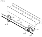
- the driving part 1030 may be coupled to a horizontal belt 1040 to rotate the horizontal belt 1040 in a clockwise or counterclockwise direction.
- Pulleys 1032 and 1042 may be installed to maintain tension of the horizontal belt 1040.
- the horizontal belt 1040 may rotate a rotation shaft to which the pulley 1051 is fixedly coupled and thus rotates the pulley 1051.
- the horizontal belt 1040 may be substituted by a chain.
- the "horizontal belt' or 'chain' may be commonly called a 'horizontal connector'.
- a pair of pulleys 1051 installed on one vertical frame 1010 is divided into an upper pulley 1051 and a lower pulley 1051.
- the vertical belt 1050 may be rotated in the clockwise or counterclockwise direction by the pair of pulleys 1051. That is, the moving direction of the vertical belt 1050 may be determined by the operation of the driving part 1030.
- the vertical belt 1050 is constituted by a belt.
- the belt may be substituted by a chain or rope.
- the vertical belt 1050 lengthily installed on the vertical frame 1010 in a vertical direction and the chain or rope that is an equivalent substitution component may be commonly called a 'vertical connector'.
- a clamp 1052 may be fixed and coupled to one spot of the vertical belt 1050.
- the clamp 1052 may be fixed and coupled to a clamp 1722 that is provided on a first hanger 1071 through a coupling piece 1522.
- the vertical belt 1050 may be moved by the operation of the driving part 1030, and the first hanger 1071 may be vertically moved by the same displacement as the one spot of the vertical belt 1050.
- a first rail 1061, a second rail 1062, and a third rail 1063 are disposed on the vertical frame 1010.
- a first hanger 1071, a second hanger 1072, and a third hanger 1073 may be respectively coupled to the rail 1061, the second rail 1062, and the third rail 1063 and then be vertically moved.
- at lest one roller 1055 may be coupled to each of the first hanger 1071, the second hanger 1072, and the third hanger 1073, and a shaft of the roller 1055 may be coupled to a roller hole 1066.
- rollers coupled to the second and third hangers 1072 and 1073 are not illustrated for convenience of description.
- One left vertical frame 1010 and one right vertical frame 1010 may be coupled to each of the first hanger 1071, the second hanger 1072, and the third hanger 1073.
- a first door 1081, a second door 1082, and a third door 1083 may be coupled between the pair of first hangers 1071, between the pair of second hangers 1072, and between the pair of third hangers 1073, respectively.
- a door connection hole 1088 may be defined in each of the hanger 1071, the second hanger 1072, and the third hanger 1073.
- each of the first door 1081, the second door 1082, and the third door 1083 may be coupled to the door connection hole 1088.
- a pulley shaft 1723 for a pulley 1091 may be disposed on each of upper and lower ends of the second hanger 1072.
- the pair of pulleys 1091 may be rotatably coupled to the pair of pulley shafts 1723.
- a belt 1009 may be coupled to contact an outer surface of each of the pair of pulleys 1091.
- the belt 1009 may be called a 'rotation connector'.
- the 'rotation connector' may be substituted by a chain in addition to the belt.
- a first coupling part 1092 may be disposed on an upper end of the first hanger 1071 and a third coupling part 1093 may be disposed on a lower end of the third hanger 1073.
- the first coupling part 1092 may be fixed and coupled to one portion of the belt 1009, and the third coupling part 1093 may be fixed and coupled to the other portion of the belt 1009.
- the horizontal belt 1040 is rotated in the clockwise (counterclockwise) direction.
- the pair of vertical belts 1050 coupled to the left vertical frame 1010 and the right vertical frame 1010 may also be rotated in the clockwise (counterclockwise) direction.
- the clamp 1052 fixed and coupled to the one spot of the vertical belt 1050 is moved along the vertical belt 1050.
- the first hanger 1071 fixed and coupled to the clamp 1052 through the coupling piece 1522 and the clamp 1052 is moved in the same direction as the clamp 1052.
- the second hanger 1072 coupled to the belt 1009 through the pulley 1091 may be moved in the same direction as the first hanger 1071.
- the pair of moved pulleys 1091 (particularly, the lower pulleys) serve as a moving pulley (i.e., movable pulley)
- a vertical moving speed of the second hanger 1072 may be a half of a vertical moving speed of the first hanger 1071.
- first and second hangers 1071 and 1072 when each of the first and second hangers 1071 and 1072 are disposed at the lowermost position, vertical central portions of the first and second hangers 1071 and 1072 are vertically spaced a predetermined distance from each other. Thus, as the first and second hangers 1071 and 1072 ascend upward, the distance between the vertical central portions may be reduced.
- a first protrusion 1711 is disposed on the lower end of the first hanger 1071. Since the first and second hangers 1071 and 1072 are coupled to each other by the above-described moving pulley, the first hanger 1071 may ascend or descend at a speed that is double that of the second hanger 1072. Here, when the first protrusion 1711 is hung on the lower end of the second hanger 1072, the first and second hangers 1071 and 1072 may ascend at the same speed. Thus, the first hanger 1071 does not ascend up to a height that is greater than that of the second hanger 1072.
- a second protrusion 1721 is disposed on the lower end of the second hanger 1072.
- the second protrusion 1721 is hung on the lower end of the third hanger 1073.
- the third hanger 1073 may be coupled to the second hanger 1072 to ascend at the same speed as the second hanger 1072. Before this, the third hanger 1073 may be maintained in a stop state.
- FIG. 4 illustrates a state in which the first protrusion 1711 is hung on the lower end of the second hanger 1072, and the second protrusion 1721 is hung on the lower end of the third hanger 1073.
- the first hanger 1071, the second hanger 1072, and the third hanger 1073 may ascend in a mutually overlapping state.
- first hanger 1071, the second hanger 1072, and the third hanger 1073 when each of the first hanger 1071, the second hanger 1072, and the third hanger 1073 is disposed at the lowermost position, the first hanger 1071, the second hanger 1072, and the third hanger 1073 may be maintained to be vertically spaced a predetermined distance from each other.
- a first stopper 1611 and a second stopper 1621 may be disposed on the first rail 1061 and the second rail 1062, respectively.
- the lower end of the second hanger 1072 may be hung on the first stopper 1611 and thus not be moved downward from the first stopper 1611
- the lower end of the third hanger 1073 may be hung on the second stopper 1621 and thus not be moved downward from the second stopper 1621.
- each of the first hanger 1071, the second hanger 1072, and the third hanger 1073 is disposed at the uppermost position, if the driving part 1030 is rotated in a reverse direction, the horizontal belt 1040 may be rotated in the counterclockwise (clockwise) direction.
- each of the first hanger 1071, the second hanger 1072, and the third hanger 1073 may be operated in the opposite way when ascending, thereby to descend.
- the first door 1081, the second door 1082, and the third door 1083 are moved together with the first hanger 1071, the second hanger 1072, and the third hanger 1073, respectively.
- the pair of vertical belts 1050 are installed on a side of the platform or a side of the railroad.
- the horizontal belt 1040 and the pair of vertical belt 1050 are always rotated in the same direction.
- the clamp 1052 has to be fixed and coupled to an outer segment 1500 of two vertical segments of the vertical belt 1050 in an opposite direction (or in an outward direction of the outer segment 1500).
- the clamp 1052 has to be fixed and coupled to the outer segment 1500 of the two vertical segments of the vertical belt 1050 in the outward direction (or a direction that is opposite to the outward direction of the outer segment 1500).
- a portion of the left vertical belt 1050 (i.e., the left vertical connector) of the left vertical frame 1010, at which the clamp 1052 is fixed and coupled may be called a 'first spot'
- a portion of the right vertical belt 1050 (i.e., the right vertical connector) of the right vertical frame 1010, at which the clamp 1052 is fixed and coupled may be called a 'second spot'.
- a housing 1090 of FIG. 1 may serve as a protector for protecting the inner components of the vertical open/close-type platform screen door 1100 according to Embodiment 1.
- a horizontally extending portion of the housing 1090 may be utilized as a space for advertisement.
- a balance weight for compensating weights of the first, second, and third hangers 1071, 1072, and 1073 and the first, second, and third doors 1081, 1082, and 1083 is not illustrated in FIGS. 1 to 6 , a balance weight as illustrated in FIG.1 may be installed.
- the third hanger 1073, the third rail 1063, and the third door 1083 may be omitted.
- the first hanger 1071 and the second hanger 1072 may not be changed in operation state.
- a portion of claims in this specification may include the contents according to the foregoing Embodiment. Among these, there may be a claim that sets forth the structure in which the third hanger 1073, the third rail 1063, and the third door 1083 are omitted.
- Embodiment 2 of the present invention will be described with reference to FIGS. 2 to 13 .
- FIG. 7 is an exploded perspective view of a platform screen door 2200 according to Embodiment 2 of the present invention.
- FIG. 8 is a partial enlarged view of a portion D of FIG. 7 .
- FIG. 9 is a view for explaining a structure of a hanger of FIG. 7 .
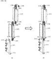
- FIG. 10 is a view for explaining a structure in which the plurality of hangers 2171, 2172, and 2173 of FIG. 7 are coupled to each other.
- FIG. 10a illustrates a structure before the plurality of hangers 2171, 2172, and 2173 are coupled to each other
- FIG. 10b illustrates a structure after the plurality of hangers 2171, 2172, and 2173 are coupled to each other.
- FIG. 11 is a view for explaining a spot at which the plurality of hangers 2171, 2172, and 2173 of FIG. 7 are coupled to each other.
- FIG. 12 is a view illustrating a state in which the plurality of hangers 2171, 2172, and 2173 of FIG. 7 ascend to overlap each other.
- FIG. 13 is a view illustrating a state in which the plurality of hangers 2171, 2172, and 2173 of FIG. 7 are vertically spaced a predetermined distance from each other.
- the platform screen door 2200 of FIG. 7 may have the same structure as the platform screen door 1100 of FIG. 1 except for a 'portion D'.
- a basic frame of the platform screen door 2200 includes a pair of vertical frames 2110 installed to be spaced apart from each other on a platform and a horizontal frame 2120 connecting upper ends of the pair of vertical frames 2110 to each other.
- the horizontal frames 2120 and the pair of vertical frames 2110 may be connected to each other by a connection reinforcing member 2121.
- the pair of vertical frames 2110, the horizontal frame 2120, and the connection reinforcing member 2121 of FIG. 7 may respectively correspond to the pair of vertical frame 1010, the horizontal frame 1020, and the connection reinforcing member 1021 of FIG. 1 .
- their component, structure, and driving method may also be the same.
- a torsion bracket 2131, a belt drooping prevention bracket 2141, and a driving part 2130, which are fixed and installed on the horizontal frame 2120 may correspond to the torsion bracket 1031, the belt drooping prevention bracket 1041, and the driving part 1030 of FIG. 1 , respectively.
- a horizontal belt 2140, pulleys 2132, 2142, and 2151, a vertical belt 2150, and a clamp 2152 of FIG. 7 may correspond to the horizontal belt 1040, the pulleys 1032, 1042, and 1051, the vertical belt 1050, and the clamp 1052 of FIG. 1 , respectively.
- a first rail 2161, a second rail 2162, and a third rail 2163 are disposed on the vertical frame 2110.
- a first hanger 2171, a second hanger 2172, and a third hanger 2173 may be respectively coupled to the first rail 2161, the second rail 2162, and the third rail 2163 and then be vertically moved.
- at least one roller 2155 may be coupled to each of the first hanger 2171, the second hanger 2172, and the third hanger 2173, and a shaft of the roller 2155 may be coupled to a roller hole 2166.
- One left vertical frame 2110 and one right vertical frame 2110 may be coupled to each of the first hanger 2171, the second hanger 2172, and the third hanger 2173.
- a first door 2181, a second door 2182, and a third door 2183 may be coupled between the pair of first hangers 2171, between the pair of second hangers 2172, and between the pair of third hangers 2173, respectively.
- At least one door connection hole 2188 may be defined in each of the first hanger 2171, the second hanger 2172, and the third hanger 2173.
- each of the first door 2181, the second door 2182, and the third door 2183 may be coupled to the door connection hole 2188 defined in each of the first hanger 2171, the second hanger 2172, and the third hanger 2173.
- a pulley shaft 2723 for a pulley 2191 may be disposed on each of upper and lower ends of the second hanger 2172.
- the pair of pulleys 2191 may be rotatably coupled to the pair of pulley shafts 2723.
- a belt 2019 may be coupled to contact an outer circumferential surface of each of the pair of pulleys 2191.
- a pulley shaft 2724 for a pulley 2195 may be disposed on each of upper and lower ends of the third hanger 2173.
- the pair of pulleys 2195 may be rotatably coupled to the pair of pulley shafts 2724.
- a belt 2029 may be coupled to contact an outer circumferential surface of each of the pair of pulleys 2195.
- the upper pulleys 2191 and 2195 of the pair of pulleys 2191 and 2195 may be called 'pulleys', and the lower pulleys 2191 and 2195 may be called 'moving pulleys'.
- a first coupling part 2192 may be disposed on an upper end of the first hanger 2171
- a second coupling part 2193 may be disposed on an upper end of the second hanger 2172
- a third coupling part 2194 may be disposed on a lower end of the third hanger 2173
- a fourth coupling part 2196 may be disposed on a portion of the vertical frame 2110.
- first coupling part 2192 may be fixed and coupled to one portion of the belt 2019, the second coupling part 2193 may be fixed and coupled to one portion of the belt 2029, the third coupling part 2194 may be fixed and coupled to the other portion of the belt 2019, and the fourth coupling part 2196 may be fixed and coupled to the other portion of the belt 2029.
- the horizontal belt 2140 is rotated in the clockwise (counterclockwise) direction.
- the pair of vertical belts 2150 coupled to the left vertical frame 2110 and the right vertical frame 2110 may also be rotated in the clockwise (counterclockwise) direction.
- the clamp 2152 fixed and coupled to the vertical belt 2150 is moved along the vertical belt 2150.
- the first hanger 2171 fixed and coupled to the clamp 2152 through the coupling piece 2522 and the clamp 2722 is moved in the same direction as the clamp 2152.
- first coupling part 2192 of the first hanger 2171 is fixed and coupled to one portion of the belt 2019, the second coupling part 2193 of the second hanger 2172 is fixed and coupled to the belt 2029, third coupling part 2194 of the third hanger 2173 is fixed and coupled to the other portion of the belt 2019, the second hanger 2172 coupled to the belt 2019 through the pulley 2191 and the third hanger 2173 coupled to the belt 2029 through the pulley 2195 may be moved in the same direction as the first hanger 2171.
- a vertical moving speed of the first hanger 2171, a vertical moving speed of the second hanger 2172, and a vertical moving speed of the third hanger 2173 may have a ratio of 3:2:1.
- the lower pulley 2191 of the pair of pulleys 2191 and the lower pulley 2195 of the other pair of pulleys 2195 may serve as the moving pulleys.
- first, second, and the third hangers 2171, 2172, and 2173 are disposed at the lowermost position, vertical central portions of the first, second, and third hangers 2171, 2172, and 2173 are vertically spaced a predetermined distance from each other.
- first, second, and third hangers 2171, 2172, and 2173 ascend upward, the distance between the vertical central portions may be reduced.
- a first protrusion 2711 is disposed on the lower end of the first hanger 2171. Since the first and second hangers 2171 and 2172 are coupled to each other by the above-described moving pulley (e.g., the pulley 2191), the first hanger 2171 may ascend or descend at a speed that is 3/2 times that of the second hanger 2172. Here, when the first protrusion 2711 is hung on the lower end of the second hanger 2172, the first and second hangers 2171 and 2172 may ascend at the same speed. Thus, the first hanger 2171 does not ascend up to a height that is greater than that of the second hanger 2172.
- a second protrusion 2721 is disposed on the lower end of the second hanger 2172.
- the second protrusion 2721 is hung on the lower end of the third hanger 2173.
- the third hanger 2173 may be coupled to the second hanger 2172 to ascend at the same speed as the second hanger 2172.
- FIG. 12 illustrates a state in which the first protrusion 2711 is hung on the lower end of the second hanger 2172, and the second protrusion 2721 is hung on the lower end of the third hanger 2172.
- the first hanger 2171, the second hanger 2172, and the third hanger 2173 may ascend in a mutually overlapping state.
- first hanger 2171, the second hanger 2172, and the third hanger 2173 when each of the first hanger 2171, the second hanger 2172, and the third hanger 2173 is disposed at the lowermost position, the first hanger 2171, the second hanger 2172, and the third hanger 2173 may be maintained to be vertically spaced a predetermined distance from each other as illustrated in FIG. 13 .
- a first stopper 2611 and a second stopper 2621 may be disposed on the first rail 2061 and the second rail 2062, respectively.
- the lower end of the second hanger 2072 may be hung on the first stopper 2611 and thus not be moved downward from the first stopper 2611, and the lower end of the third hanger 2073 may be hung on the second stopper 2621 and thus not be moved downward from the second stopper 2621.
- each of the first hanger 2171, the second hanger 2172, and the third hanger 2173 is disposed at the uppermost position, if the driving part 2130 is rotated in a reverse direction, the horizontal belt 2140 may be rotated in the counterclockwise (clockwise) direction.
- each of the first hanger 2171, the second hanger 2172, and the third hanger 2173 may be operated in the opposite way when ascending, thereby to descend.
- the first door 2181, the second door 2182, and the third door 2183 are moved together with the first hanger 2171, the second hanger 2172, and the third hanger 2173, respectively.
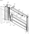
- FIG. 14 is a front view of a platform screen door according to an embodiment of the present invention.
- the platform screen door according to Embodiment 3 of the present invention may include first and second vertical frames 100 and 200 installed on a platform 500 and a horizontal frame 300 connecting upper ends of the first and second vertical frames 100 and 200 to each other.
- the first vertical frame 100 may be called a 'first frame' or 'left vertical frame'
- the second vertical frame 200 may be called a 'second frame' or 'right vertical frame'.
- a laser scan sensor 600 may be coupled to a lower end of a left side of the horizontal frame 300. Also, three doors 10, 20, and 30 may be movably and vertically coupled between the left frame 100 and the right frame 200.
- the third door 10 may have a plate shape.
- the third door 10 may include a pattern part 1005 for forming advertisement areas 1001 to 1004 and various shapes.
- the third door 10 may be formed of a finishing material such as glass and polycarbonate.
- the 'third door' may be called an 'upper door'.
- a five-line rope 25 extending in a horizontal direction may be disposed on the second door 20.
- holder parts 210 and 220 may be fixed to both ends of the rope.
- the 'second door' may be called an 'intermediate door'.
- a five-line rope 35 extending in the horizontal direction may be fixed to holder parts 310 and 320.
- the 'first door' may be called a 'lower door'.
- an end of the rope 35 may be connected to a first coupling part 311 of the holder part 310.
- the holder part 310 and a first block 32 may be connected to each other through a second coupling part 312 of the holder part 310.
- a protection cover 280 for protecting the portion for connecting the ropes 25 and 35 to the holder parts 210, 220, 310, and 320 may be coupled to both ends of each of ropes.
- an ultrasonic sensor 50 may be disposed on a sensor installation part 501 disposed on a lower end of each of the holder parts 310 and 320 of the first door 30.
- the second door 20 may have the same structure as the first door 30 except that the sensor installation part 501 is not provided to the first door 30.
- the second door 20 is constituted and installed through the same method as the first door 30.
- the third door 10 is different from the second door 20 and the first door 30 in that the third door 10 has a plate shape, but the rope shape, the third door 10 may have a shape similar to those of the second door 20 and the first door 30.
- the third door 10 when the doors 10, 20, and 30 are closed, the third door 10, the second door 20, and the first door 30 may be disposed in order from an upper side.
- the lowermost rope of the second door 20 may overlap the uppermost rope of the first door 30.
- the three doors may vertically ascend at the same time.
- the three doors 10, 20, and 30 may gradually overlap each other.
- the three doors When the doors are completely opened, the three doors may fully overlap each other.
- a moving distance of each of the doors a moving distance of the second door 20 may be less than that of the third door 10, and a moving distance of the first door 30 may be greater than that of the second door 20.
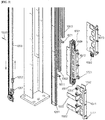
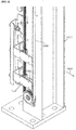
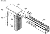
- FIGS. 16a , 16b , 16c , and 17 a structure of the vertical frame will be described in detail with reference to FIGS. 16a , 16b , 16c , and 17 .
- a base part 191 of the left frame 100 may be directly fixed and connected to a platform 500.
- a lower end of each of H-beams 198 and 199 may be fixed and coupled to the base part 191.
- an upper end of each of the H-beams 198 and 199 may be fixed and coupled to a housing 301 of the horizontal frame by connection pieces 192 and 193.
- a housing surrounding the H-beams 198 and 199 may include a housing front surface 151, a housing rear surface 152, a housing side surface 153, a housing top surface 156, and housing corners 154 and 155.
- the 'housing' may serve as a protection member for protecting inner components surrounded thereby.
- the H-beam 198 may be fixed and coupled to the housing front surface 151 by the connection piece 161, and each of blocks 12, 22, and 32 respectively connected to the first door 30, the second door 20, and the third door 10 may be fixed and coupled to a moving slit part 110.
- the slit part 110 may include three slits 11, 21, and 31 that vertically and lengthily extend.
- the blocks 12, 22, and 32 corresponding to the slits 11, 21, and 31 may be movably coupled within the slits 11, 21, and 31, respectively.
- the slits 11, 21, and 31 may have lengths different from each other. That is, the third slit 11 may have a length less than that of the second slit 21, and the second slit 21 may have a length less than that of the first slit 13. Also, upper ends of the first, second, and third slits 11, 21, and 31 may be disposed at the same height.
- the third block 12 corresponding to the third slit 11 may be coupled to the upper door 10
- the second block 22 corresponding to the second slit 21 may be coupled to the intermediate door 20
- the first block 32 corresponding to the first slit 31 may be coupled to the lower door 30.
- Holes 171 and 172 for supporting a rotation shaft 130 may be defined one spot of an upper end of the H-beam 199.
- a second pulley 132 may be rotatably coupled to the rotation shaft 130 on a front surface of the H-beam 199.
- a rotation shaft 131 may be installed on an intermediate end of the H-beam 199, and a second pulley 133 may be rotatably coupled to the rotation shaft 131.
- the second pulley 132 and the second pulley 133 may have the same diameter.
- a second vertical connector (a second vertical belt) 134 may be coupled to the pair of second pulleys 132 and 133.
- one spot of the second vertical connector 134 may be fixed and connected to the third block (the upper block) 12.
- the pulley 142 may be rotatably coupled to the rotation shaft 130 on a rear surface of the H-beam 199.
- a rotation shaft 141 may be installed on a lower end of the H-beam 199, and a pulley 143 may be rotatably coupled to the rotation shaft 141.
- the pulley 142 and the pulley 143 may have the same diameter.
- a circumferential length of the pulleys 142 and 143 may be three times of that of the second pulleys 132 and 133.
- a vertical connector (a vertical belt) 144 may be coupled to the pair of pulleys 142 and 143.
- one spot of the vertical connector 144 may be fixed and connected to the first block (the lower block) 32.
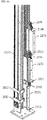
- a movement principle of the second vertical connector 134 may be described as follows. First, the horizontal belt 302 may be rotated by an operation of a driving part (e.g., reference numeral 1030 of FIG. 2 ) installed in the horizontal frame 300. Here, the horizontal belt 302 may rotate the rotation shaft 130. The rotation shaft 130 may rotate the second pulley 132. The second pulley 132 may rotate the second vertical connector 134. The second vertical connector 134 may rotate the second pulley 133. When the one spot is vertically moved by the second vertical connector 134 connected to the third block 12, the third block 12 may be vertically moved.
- a driving part e.g., reference numeral 1030 of FIG. 2
- the first block 32 may be fixed and connected to the one spot of the vertical connector 144.
- the first block 32 may be vertically moved according to the rotation of the vertical connector 144.
- the second pulley 132 and the pulley 142 may be connected to the same rotation shaft 130 and thus rotated at the same angular velocity.
- a linear velocity of the second vertical connector 134 connected to the second pulley 132 may be 1/2 of that of the vertical connector 144 connected to the pulley 142.
- the first block 32, the second block 22, and the third block 12 may be moved by distances 1800 mm, 1350 mm, and 900 mm from the lowermost end that is fully closed to the uppermost end that is fully opened.
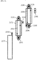
- the second block 22 may be connected the first block 32 through a moving pulley 3191.
- the moving pulley 3191 and the first pulley 3192 are fixedly installed on the second block 22, and the first connector (belt) 3019 is wound around the moving pulley 3191 and the first pulley 3192.
- a portion (a first coupling part 3193) of the first block 32 may be fixed and coupled to one spot (that is expressed in a black circular shape) of the first connector 3019, and a portion 3194 disposed on the third block 12 may be fixed and coupled to the other spot (that is expressed in a black diamond shape) of the first connector 3019.
- the first block 32 may vertically move the second block 22 through the first connector 3019.
- the third block (the upper block) is vertically moved by a distance L
- the second block (the intermediate block) 22 may be vertically moved by a distance 1.5 L.
- vertical moving speeds of the third block 12, the second block 22, and the first block 32 may be designed to have a ratio of 1:1.5:2.
- the third block 12, the second block 22, and the first block 32 may be guided and moved by a slit part 110 and a rail disposed on the rail part 120.
- the rail part 120 may serve as a guide part along which a weight (not shown) is moved.
- first block structures of the first block, the second block, and the third block will be described with reference to FIG. 19 .
- the structure of the first block will be mainly described as an example.
- FIGS. 19(a), 19(b), and 19(c) are plan, front, and side views of the first block 32, respectively.
- a hole 322 for supporting a rotation shaft 323 may be defined in the first block 32.
- FIG. 19 illustrates an example in which total 10 rotation shafts 323 and total 10 holes 322 are provided.
- the holes 322 may be provided for coupling a wheel 320.
- reference numeral may be given to only one hole.
- the wheel 320 may be coupled to each of the rotation shafts 323 so that the wheel 320 is moved along the rail. Although all 10 wheels 320 are illustrated in FIG. 18(c) , for convenience of description, the wheels 320 may not illustrated or be expressed as a dotted line in FIG. 19(b) .
- a coupling part 311 disposed on the first block 32 may be coupled to a coupling part 312 (see FIG. 18e ) disposed on a holder part 310 of the first door 30 by using a coupling member.
- the first block 32 may include a head part 1, a body part 2, a wheel 320 connected to an end of a left side of the body part 2, and a belt connection part 321 connected to a center of an upper portion of the body part 2.
- the belt connection part 321 may be fixed and coupled to one end of the above-described second vertical connector 134.
- the head part 1 and the body part 2 may be integrated with each other.
- the first block 32 may be coupled to the vertical frame through following processes. First, the body part 2 may be inserted into a first slit 31. Here, the head part 1 may be hung on an edge of the first slit 31. Then, the wheel 320 and the belt connection part 321 may be coupled to the body part 2. Then, the belt connection part 321 may be fixed and coupled to the second vertical connector 134. Here, the wheels 320 may be aligned to correspondingly contact the rail part 120.
- the head part 1 may have a first width W1 greater than a second width W2 of the body part 2. Also, the first width W1 may be greater than a third width of the first slit, and the second width W2 may be less than the third width.
- a sensor 50 may be installed on a lower end of the first door 30, i.e., a lower end of the holder part 310.
- the sensor 50 may be provided in a pair on left and right sides.
- the sensor 50 may detect a person's head, which may exist directly under the first door 30, to provide a signal for emergency stopping an operation of the screen door.
- the sensor 50 may be an ultrasonic type sensor.
- other technologies may be adopted as a specific detecting manner.
- the senor 50 may be installed inside the first slit 31, i.e., the vertical frame.
- the sensor may be installed outside the first slit 31, i.e., the vertical frame.
- the first slit 31 has a small width.
- a brush for preventing dusts from being introduced may be installed on the first slit 31.
- the sensor 50 has a large size, when the sensor 50 is installed inside the first slit 31, a signal to be transmitted from or received into the sensor 50 may be blocked by an edge portion of the first slit 31 because the first slit 31 has a narrow width.
- the senor 50 may be installed outside the first slit 31, i.e., the vertical frame.
- the holder part 310 since the holder part 310 is disposed outside the first slit 31, the sensor 50 may be installed on a sensor installation part 501 provided on a lower end of the holder part 310.
- a wired cable connected to the sensor 50 may extend through the insides of the horizontal frame and the vertical frame of the platform screen door and be connected to a control part through the first slit 31.
- the platform screen door includes: a main body including a pair of vertical frames 2110; first and second doors 2181 and 2182 disposed between the pair of vertical frames 2110; a first moving pulley 2191 coupled to the second door 2182 to vertically move the second door 2182; a first connector 2019 for driving the first moving pulley 2191; and driving assemblies 1008 and 1009 installed on the main body to drive the first connector 2019.
- the first door 2181 may be fixed and coupled to one spot of a driving segment of the first connector 2019.
- the one spot of the driving segment of the first connector 2019 may represent a left portion of the first connector 2019.
- the platform screen door according to Embodiment 4 of the present invention may further include a first pulley 2191.
- the first pulley 2191 may be rotatably coupled to the second door 2181.
- the first connector 2019 may be a belt for connecting the first moving pulley 2191 to the first pulley 2191.
- the second door 2182 may receive vertical force from the first door 2181 through the first moving pulley 2191.
- the first door 2181 and the second door 2182 may be moved along rails 2161 and 2162 provided on the vertical frame 2110.
- the platform screen door according to Embodiment 4 of the present invention may further includes: a horizontal frame disposed on upper portions of the pair of vertical frames 2110; and one driving part installed on the main body to drive the driving assemblies 1008 and 1009 through a horizontal connector 2140.
- the driving assembles 1008 and 1009 may include: a left driving assembly 1008 installed on a left vertical frame 2110 of the pair of vertical frames 2110 to vertically move a left end of the first door 2181; and a right driving assembly 1009 installed on a right vertical frame 2110 of the pair of vertical frames 2110 to vertically move a right end of the first door 2181.
- the left driving assembly 1008 and the right driving assembly 1009 may be driven at the same time by the one driving part.
- the horizontal connector 2140 may include a belt, a chain, or a rope.
- the horizontal connector 2140 may be disposed to extend along the horizontal frame 2120, and a pulley 1042 for preventing the horizontal connector 2140 from drooping may be installed on the horizontal frame 2120.
- the driving assemblies 1008 and 1009 may include a pair of pulleys 2151, a vertical connector 2150 rotated by the pair of pulleys 2151, a first rail 2161 disposed on the vertical frame, and a first hanger 2171 for fixing and coupling a portion of the vertical connector 2150 to the first door 2181 and vertically moved along the first rail 2161.
- a rotation shaft of the upper first pulley 2151 of the pair of pulleys 2151 may be coupled to the horizontal connector 2149 and thus rotated by the horizontal connector 2140.
- the platform screen door according to Embodiment 4 of the present invention may further include: a first hanger 2171 connected to a left side of the first door 2181; and a second hanger 2172 connected to a left side of the second door 2182 and including the first moving pulley.
- the first connector 2019 may transmit the vertical force from the first hanger 2171 to the second hanger 2172 through the first moving pulley 2191.
- a first coupling part 2192 disposed on the first hanger 2171 may be fixed and coupled to a portion of the first connector 2019.
- the left driving assembly 1009 may include a left vertical connector 2150 and a left first hanger 2171 for fixing and coupling a portion of the left vertical connector 2150 to a left end of the first door 2181.
- the right driving assembly 1009 may include a right vertical connector 2150 and a right first hanger 2171 for fixing and coupling a portion of the right vertical connector 2150 to a right end of the first door 2181.
- the left end of the first door 2181 may be fixed and coupled to a first spot of the left vertical connector 2150
- the right end of the first door 2181 may be fixed and coupled to a second spot of the right vertical connector 2150.
- the first spot and the second spot may be selected to be always directed in the same direction.
- all of the left driving assembly 1008 and the right driving assembly 1009 may be disposed on a side of the platform or the railroad.
- a platform screen door includes: first, second, and third doors 2181, 2182, and 2183 disposed between a pair of vertical frames 2110; first, second, and third hangers 2171, 2172, and 2173 respectively connected to left and side sides of the first, second, and third doors 2181, 2182, and 2183; a first moving pulley 2191 coupled to the second hanger 2172 to vertically move the second door 2182; a second moving pulley 2195 coupled to the third hanger 2173 to vertically move the third door 2183; and first and second connectors 2019 and 2029 for respectively driving the first and second moving pulleys 2191 and 2195.
- the first hanger 2171 may be fixed and coupled to one spot of the first driving segment of the first connector 2019, and the second hanger 2172 may be fixed and coupled to one spot of the second driving segment of the second connector 2029.
- the one spot of the first driving segment of the first connector 2019 may represent a left portion of the first connector 2019, and the one spot of the second driving segment of the second connector 2029 may represent a left portion of the second connector 2029.
- the platform screen door according to Embodiment 5 of the present invention may further include a first pulley 2191.
- the first pulley 2172 may be rotatably coupled to the second hanger 2172.
- the first connector 2019 may be a belt for connecting the first moving pulley 2191 to the first pulley 2191.
- the platform screen door according to Embodiment 5 of the present invention may further include a second pulley 2195.
- the second pulley 2195 may be rotatably coupled to the third hanger 2173, and the second connector 2029 may be a belt for connecting the second moving pulley 2195 to the second pulley 2195.
- a first coupling part 2192 disposed on the first hanger 2171 may be fixed and coupled to a portion of the first connector 2019, and a second coupling part 2194 disposed on the third hanger 2173 may be fixed and coupled to a portion of the second connector 2029.
- the first hanger 2171, the second hanger 2172, and the third hanger 2173 may be moved along rails 2161, 2162, and 2163 provided on the vertical frame 2110.
- the platform screen door according to Embodiment 6 includes: a main body including a pair of vertical frames 100 and 200; first and second doors 30 and 20 disposed between the pair of vertical frames 100 and 200; a moving pulley 3191 coupled to the second door 20 to vertically move the second door 20; a first connector 3019 for driving the moving pulley 3191; and a driving assembly 4100 installed on the main body to drive the first connector 3019.
- the first door 30 may be fixed and coupled to one spot of the driving assembly 4100 of the first connector 3019.
- the term 'fixed and coupled' may be concept including a structure in which the first door 30 is a portion of the driving assembly 4100.
- the 'horizontal connector' and the 'vertical connector' may be called a 'first connector' and a 'second connector', respectively. Also, it may be unnecessary that the 'horizontal connector' has to lengthily extend in the horizontal direction, and the 'vertical connector' has to lengthily extend in the vertical direction.
- each of the door leafs moved in the vertical direction has the plate shape or rope shape
- the present embodiment is not limited thereto.
- the door leafs may include at least one long rod that extends in the left/right direction.
- each of the door leafs may be coupled to at least one structure such as the plate, the rope, and the rod.
- a surface of each of the door leafs may be formed of a finishing material such as glass and polycarbonate.
Landscapes
- Engineering & Computer Science (AREA)
- Mechanical Engineering (AREA)
- Civil Engineering (AREA)
- Structural Engineering (AREA)
- Transportation (AREA)
- Architecture (AREA)
- Power-Operated Mechanisms For Wings (AREA)
- Platform Screen Doors And Railroad Systems (AREA)
- Refuge Islands, Traffic Blockers, Or Guard Fence (AREA)
Applications Claiming Priority (3)
| Application Number | Priority Date | Filing Date | Title |
|---|---|---|---|
| KR20130109886 | 2013-09-12 | ||
| KR1020140031833A KR101606827B1 (ko) | 2013-09-12 | 2014-03-18 | 움직도르래를 이용한 승하강 방식의 플랫폼 스크린도어 |
| PCT/KR2014/008493 WO2015037927A1 (fr) | 2013-09-12 | 2014-09-11 | Porte-écran du type à ouverture/fermeture verticale à segments multiples actionnée par une poulie mobile |
Publications (2)
| Publication Number | Publication Date |
|---|---|
| EP3045370A1 true EP3045370A1 (fr) | 2016-07-20 |
| EP3045370A4 EP3045370A4 (fr) | 2017-05-03 |
Family
ID=53024597
Family Applications (1)
| Application Number | Title | Priority Date | Filing Date |
|---|---|---|---|
| EP14843504.3A Withdrawn EP3045370A4 (fr) | 2013-09-12 | 2014-09-11 | Porte-écran du type à ouverture/fermeture verticale à segments multiples actionnée par une poulie mobile |
Country Status (5)
| Country | Link |
|---|---|
| US (1) | US20160222716A1 (fr) |
| EP (1) | EP3045370A4 (fr) |
| JP (1) | JP6290427B2 (fr) |
| KR (1) | KR101606827B1 (fr) |
| CN (1) | CN105555632B (fr) |
Families Citing this family (16)
| Publication number | Priority date | Publication date | Assignee | Title |
|---|---|---|---|---|
| DE102014215857A1 (de) * | 2014-08-11 | 2016-02-11 | Init Innovative Informatikanwendungen In Transport-, Verkehrs- Und Leitsystemen Gmbh | Verfahren zum Leiten der Fahrgäste öffentlicher Verkehrsmittel |
| EP3106365B1 (fr) * | 2015-06-19 | 2018-07-11 | Faiveley Transport Tours | Systeme de fixation d'un module de porte paliere sur un quai et procede de montage associe |
| AU2016204361B2 (en) * | 2015-06-26 | 2021-07-08 | Aneeta Window Systems (Vic) Pty Ltd | A sliding window arrangement |
| KR102010238B1 (ko) * | 2018-09-13 | 2019-08-13 | 김기웅 | 로드킬 방지 자동개폐장치 |
| KR102149715B1 (ko) | 2019-01-15 | 2020-08-31 | 김중삼 | 움직도르래를 이용한 도어 구동장치 |
| CN109720356A (zh) * | 2019-02-13 | 2019-05-07 | 中国铁道科学研究院集团有限公司电子计算技术研究所 | 一种升降站台门 |
| KR102046459B1 (ko) * | 2019-06-03 | 2019-11-20 | 신판주 | 스크린도어의 프레임 모듈 및 이를 이용한 플랫폼 스크린 도어 |
| KR102168537B1 (ko) | 2019-08-14 | 2020-10-21 | 주식회사 삼흥정밀 | 개스스프링과 움직도르래를 이용한 반자동식 슬라이딩 도어 |
| CN110778238A (zh) * | 2019-09-25 | 2020-02-11 | 奇点物联网股份有限公司 | 一种用于施工维修装饰门挡 |
| KR102502694B1 (ko) * | 2020-07-21 | 2023-02-23 | 주식회사 에스케이디 하이테크 | 승객 및 보행자 안전장치 |
| GB2610340A (en) * | 2020-07-21 | 2023-03-01 | Skd Hi Tec Co Ltd | Safety apparatus for passengers or pedestrians |
| KR20220011543A (ko) * | 2020-07-21 | 2022-01-28 | 주식회사 에스케이디 하이테크 | 전동차 플랫폼 안전장치 |
| CN112252883B (zh) * | 2020-10-14 | 2022-07-12 | 日立楼宇技术(广州)有限公司 | 轨道交通站台门的闭合方法、装置、设备和存储介质 |
| CN113047761B (zh) * | 2021-04-02 | 2022-07-01 | 南京启越机电设备有限公司 | 一种升降式站台门机构 |
| KR102845499B1 (ko) * | 2023-06-28 | 2025-08-11 | 서종용 | 난간대 매립형 자동 창호 |
| CN120007055B (zh) * | 2025-04-16 | 2025-07-25 | 福建安麟智能科技股份有限公司 | 一种多组拉绳的安全门结构 |
Family Cites Families (15)
| Publication number | Priority date | Publication date | Assignee | Title |
|---|---|---|---|---|
| US1439373A (en) * | 1920-06-16 | 1922-12-19 | Perfect Window Regulator Compa | Window opening and closing mechanism |
| US1810496A (en) * | 1926-12-03 | 1931-06-16 | Peelle Co The | Elevator door |
| US2154421A (en) * | 1938-04-04 | 1939-04-18 | Arthur W Cunningham | Collapsible gate |
| US2373023A (en) * | 1940-04-01 | 1945-04-03 | Eugene W Goodwin | Sectional sliding door |
| US2425016A (en) * | 1944-12-19 | 1947-08-05 | Edgar R Weaver | Hangar door operating mechanism |
| US3977123A (en) * | 1975-06-25 | 1976-08-31 | Whiting Roll-Up Door Mfg. Corporation | Upwardly-acting door structure |
| AR213370A1 (es) * | 1978-06-12 | 1979-01-15 | Pecchioni V | Unidad integral de puerta levadiza y de marco para la misma |
| EP0602035B1 (fr) * | 1991-01-16 | 2003-12-17 | Albany Door Systems AB | Porte |
| US5271183A (en) * | 1992-09-25 | 1993-12-21 | Rite-Hite Corporation | Safety barrier assembly |
| JP2593605Y2 (ja) * | 1992-12-25 | 1999-04-12 | トピー工業株式会社 | プラットホームにおけるガードフェンス |
| JP4551466B2 (ja) * | 2002-10-29 | 2010-09-29 | ナブテスコ株式会社 | ダブルスライド式プラットホームゲート |
| US6860311B1 (en) * | 2003-07-02 | 2005-03-01 | Robert L Minor | Telescopic door and panel forming apparatus |
| KR100601112B1 (ko) * | 2005-02-14 | 2006-07-19 | 주식회사 에스케이디 하이테크 | 전동차 플랫폼의 안전장치 |
| JP2011201340A (ja) * | 2010-03-24 | 2011-10-13 | Tokyu Car Corp | プラットホームゲート装置 |
| KR101344995B1 (ko) * | 2011-03-01 | 2013-12-24 | 한성무 | 전동차 플랫폼 안전장치 |
-
2014
- 2014-03-18 KR KR1020140031833A patent/KR101606827B1/ko active Active
- 2014-09-11 EP EP14843504.3A patent/EP3045370A4/fr not_active Withdrawn
- 2014-09-11 US US15/021,747 patent/US20160222716A1/en not_active Abandoned
- 2014-09-11 JP JP2016542639A patent/JP6290427B2/ja active Active
- 2014-09-11 CN CN201480050352.6A patent/CN105555632B/zh active Active
Also Published As
| Publication number | Publication date |
|---|---|
| EP3045370A4 (fr) | 2017-05-03 |
| JP6290427B2 (ja) | 2018-03-07 |
| CN105555632A (zh) | 2016-05-04 |
| JP2016536215A (ja) | 2016-11-24 |
| KR20150030587A (ko) | 2015-03-20 |
| US20160222716A1 (en) | 2016-08-04 |
| CN105555632B (zh) | 2018-09-04 |
| KR101606827B1 (ko) | 2016-03-28 |
Similar Documents
| Publication | Publication Date | Title |
|---|---|---|
| US20160222716A1 (en) | Multi-stage vertical open/close-type screen door operated by moving pulley | |
| KR101471543B1 (ko) | 장애물 감지장치를 구비하는 승하강 방식의 전동차 플랫폼 안전장치 | |
| KR20140007980A (ko) | 장애물 감지장치를 구비하는 승하강 방식의 전동차 플랫폼 안전장치 | |
| EP2143682A1 (fr) | Dispositif d'encadrement de porte pour un ascenseur | |
| KR101391453B1 (ko) | 전동차 플랫폼 안전장치 | |
| JP5044102B2 (ja) | エレベータの多段ケージの各ケージを正確に位置決めする装置 | |
| KR20150013411A (ko) | 수직개폐형 스크린도어의 승하강장치 | |
| CN112173921A (zh) | 用于限制电梯行进线缆中的摆动的装置 | |
| KR20140046271A (ko) | 방화 리프트 | |
| KR101406018B1 (ko) | 승하강 방식의 안전장치 | |
| KR101500875B1 (ko) | 전동차 플랫폼 안전장치 | |
| RU2437823C2 (ru) | Конструкция двери лифта | |
| KR101802496B1 (ko) | 프레임과의 연결부에 가동연결부가 구비된 수직개폐형 스크린도어를 포함하는 플랫폼 스크린도어 | |
| JP2017066809A (ja) | 車両飛び込み防止装置とその運転方法 | |
| CN106232515A (zh) | 电梯设备 | |
| JP7083581B2 (ja) | 工事用扉 | |
| JP6976108B2 (ja) | ホーム柵 | |
| JP6789501B2 (ja) | ホームドア | |
| RU2424175C2 (ru) | Конструкция двери лифта | |
| KR20130126561A (ko) | 승하강 방식의 전동차 플랫폼 안전장치 | |
| CN102561930B (zh) | 门装置 | |
| KR101740468B1 (ko) | 턴버클을 이용하여 로프의 장력을 조절하는 로프타입의 수직개폐형 스크린도어 | |
| KR101740469B1 (ko) | 경량형 수직개폐 스크린도어 | |
| JP7438842B2 (ja) | ホームドア装置 | |
| JP2013189294A (ja) | エレベータのドア装置 |
Legal Events
| Date | Code | Title | Description |
|---|---|---|---|
| PUAI | Public reference made under article 153(3) epc to a published international application that has entered the european phase |
Free format text: ORIGINAL CODE: 0009012 |
|
| 17P | Request for examination filed |
Effective date: 20160412 |
|
| AK | Designated contracting states |
Kind code of ref document: A1 Designated state(s): AL AT BE BG CH CY CZ DE DK EE ES FI FR GB GR HR HU IE IS IT LI LT LU LV MC MK MT NL NO PL PT RO RS SE SI SK SM TR |
|
| AX | Request for extension of the european patent |
Extension state: BA ME |
|
| DAX | Request for extension of the european patent (deleted) | ||
| A4 | Supplementary search report drawn up and despatched |
Effective date: 20170331 |
|
| RIC1 | Information provided on ipc code assigned before grant |
Ipc: E01F 1/00 20060101ALI20170327BHEP Ipc: E01F 13/00 20060101ALI20170327BHEP Ipc: B61B 1/02 20060101AFI20170327BHEP |
|
| STAA | Information on the status of an ep patent application or granted ep patent |
Free format text: STATUS: EXAMINATION IS IN PROGRESS |
|
| 17Q | First examination report despatched |
Effective date: 20180914 |
|
| GRAP | Despatch of communication of intention to grant a patent |
Free format text: ORIGINAL CODE: EPIDOSNIGR1 |
|
| STAA | Information on the status of an ep patent application or granted ep patent |
Free format text: STATUS: GRANT OF PATENT IS INTENDED |
|
| INTG | Intention to grant announced |
Effective date: 20200116 |
|
| STAA | Information on the status of an ep patent application or granted ep patent |
Free format text: STATUS: THE APPLICATION IS DEEMED TO BE WITHDRAWN |
|
| 18D | Application deemed to be withdrawn |
Effective date: 20200603 |