EP3045609A1 - Ein dachfenster oder dachausstiegsfenster mit einem nach aussen offenbaren flügelrahmen mit einer befestigungsanordnung zur befestigung am oberen abdeckelement - Google Patents
Ein dachfenster oder dachausstiegsfenster mit einem nach aussen offenbaren flügelrahmen mit einer befestigungsanordnung zur befestigung am oberen abdeckelement Download PDFInfo
- Publication number
- EP3045609A1 EP3045609A1 EP16151784.2A EP16151784A EP3045609A1 EP 3045609 A1 EP3045609 A1 EP 3045609A1 EP 16151784 A EP16151784 A EP 16151784A EP 3045609 A1 EP3045609 A1 EP 3045609A1
- Authority
- EP
- European Patent Office
- Prior art keywords
- mounting
- upper casing
- roof window
- fixing
- sash
- Prior art date
- Legal status (The legal status is an assumption and is not a legal conclusion. Google has not performed a legal analysis and makes no representation as to the accuracy of the status listed.)
- Granted
Links
- 239000002184 metal Substances 0.000 claims abstract description 18
- 230000000712 assembly Effects 0.000 claims abstract description 6
- 238000000429 assembly Methods 0.000 claims abstract description 6
- 238000009434 installation Methods 0.000 claims description 30
- 230000000694 effects Effects 0.000 claims description 7
- 238000003780 insertion Methods 0.000 claims description 5
- 230000037431 insertion Effects 0.000 claims description 5
- 238000005452 bending Methods 0.000 abstract description 4
- 239000000243 solution Substances 0.000 description 13
- XLYOFNOQVPJJNP-UHFFFAOYSA-N water Substances O XLYOFNOQVPJJNP-UHFFFAOYSA-N 0.000 description 9
- 238000007789 sealing Methods 0.000 description 7
- 230000000903 blocking effect Effects 0.000 description 4
- 238000009736 wetting Methods 0.000 description 3
- 230000004888 barrier function Effects 0.000 description 2
- 230000005489 elastic deformation Effects 0.000 description 2
- 239000011521 glass Substances 0.000 description 2
- 230000013011 mating Effects 0.000 description 2
- 230000035515 penetration Effects 0.000 description 2
- 230000002411 adverse Effects 0.000 description 1
- 230000015572 biosynthetic process Effects 0.000 description 1
- 239000011248 coating agent Substances 0.000 description 1
- 238000000576 coating method Methods 0.000 description 1
- 230000006835 compression Effects 0.000 description 1
- 238000007906 compression Methods 0.000 description 1
- 238000005336 cracking Methods 0.000 description 1
- 230000006866 deterioration Effects 0.000 description 1
- 238000006073 displacement reaction Methods 0.000 description 1
- 239000012634 fragment Substances 0.000 description 1
- 238000001746 injection moulding Methods 0.000 description 1
- 238000004519 manufacturing process Methods 0.000 description 1
- 230000002787 reinforcement Effects 0.000 description 1
- 230000035882 stress Effects 0.000 description 1
- 230000008646 thermal stress Effects 0.000 description 1
Images


Classifications
-
- E—FIXED CONSTRUCTIONS
- E04—BUILDING
- E04D—ROOF COVERINGS; SKY-LIGHTS; GUTTERS; ROOF-WORKING TOOLS
- E04D13/00—Special arrangements or devices in connection with roof coverings; Protection against birds; Roof drainage ; Sky-lights
- E04D13/03—Sky-lights; Domes; Ventilating sky-lights
- E04D13/035—Sky-lights; Domes; Ventilating sky-lights characterised by having movable parts
- E04D13/0351—Sky-lights; Domes; Ventilating sky-lights characterised by having movable parts the parts pivoting about a fixed axis
- E04D13/0354—Sky-lights; Domes; Ventilating sky-lights characterised by having movable parts the parts pivoting about a fixed axis the parts being flat
-
- E—FIXED CONSTRUCTIONS
- E04—BUILDING
- E04D—ROOF COVERINGS; SKY-LIGHTS; GUTTERS; ROOF-WORKING TOOLS
- E04D13/00—Special arrangements or devices in connection with roof coverings; Protection against birds; Roof drainage ; Sky-lights
- E04D13/03—Sky-lights; Domes; Ventilating sky-lights
-
- E—FIXED CONSTRUCTIONS
- E04—BUILDING
- E04D—ROOF COVERINGS; SKY-LIGHTS; GUTTERS; ROOF-WORKING TOOLS
- E04D13/00—Special arrangements or devices in connection with roof coverings; Protection against birds; Roof drainage ; Sky-lights
- E04D13/03—Sky-lights; Domes; Ventilating sky-lights
- E04D13/0305—Supports or connecting means for sky-lights of flat or domed shape
- E04D13/031—Supports or connecting means for sky-lights of flat or domed shape characterised by a frame for connection to an inclined roof
Definitions
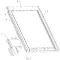
- the invention relates to a roof window or hatch comprising preferably two mutually symmetrical fixing assemblies for the upper casing, the assemblies being arranged symmetrically on the upper corners of the sash openable outwards, while the upper casing is mounted on the sash elements, simultaneously providing a seal protecting from all weather conditions for the connection of the upper casing with side casings.
- the casings are basically installed on the whole circumference of the sash frame.
- an openable roof window has basically four casings, covering the side elements, the upper elements and the lower elements of the window.
- the sash is an element comprising preferably a plurality of symmetrical elements arranged symmetrically in relation to both symmetry planes, thus the opposite fixing assemblies for the casing elements contain features and shapes being mutual mirror images.
- the casings of roof windows typically formed from metal sheets, protect the window frame and the window sash from adverse weather conditions.
- the casings of the window frame are generally installed immovably and mate with a flange sealing the connection of the window frame with the roof cover, while the casings of the window sash are in general connected immovably with their corresponding sash frame members.
- a complete casing set is most often composed of two side casings, an upper casing and a lower casing.
- the casings made of metal sheets are most often fixed using screws, catch pawls or rivets, and feature mounting holes intended for this purpose.
- the fixing points utilise installation slots located in the sash frame members, most often in the corners, while the installation slots may be immovable or slidable, if a compensation for differences resulting from working tolerances and thermal expansion of the sash frame members and the casings is required.
- the second fixing point of the casing is constituted by installation slots slidable along the sash frame member.
- One of known solutions is a set composed of a comb joint on one end of the casing and a snap-on joint on its other end, described in Patent Description no. PL 212427 .
- the set was disclosed for use in a pivot window, with a relatively short casing element of the sash, and the snap-on joint requires rather strict working tolerances. In case of large temperature changes leading to various thermal elongations, it may pose an installation problem while connecting the snap-on elements.
- this system does not provide any possibility of fixing the casing on the sash element tightly and rigidly, which would eliminate vibrations and noise caused by the casing, for instance as a result of turbulences of the surrounding air.
- One of such solutions is a set of elements for fixing the casings, disclosed in application no. EP 2666926 A1 , the set being based on a plastic corner element, comprising elements for quick fastening to fixed elements of the window or those of the window sash.
- the corner element is slipped onto the metal sheet casing profile, then the set is fixed to the sash frame.
- This solution enables fast installation of the casing elements on the window sash and it is aesthetic, however it does not provide for any necessity to compensate the thermal elongation of the metal sheet casings.
- the temperature rises and the casings profiles elongate leading to stresses in the mating elements when the compensation is not provided for, which may result in their cracking. It is of a particular importance in case of use of more and more popular plastic corner connectors featuring lower mechanical strength, where thermal stresses may lead to their deformation or failure.
- a compensating element or system is necessary in such solutions.
- the aim of the proposed solution consists in the provision of a fixing assembly for the upper casing of a roof window eliminating the necessity to use connector elements, requiring a breach in the structural continuity of the casing (e.g. installation holes), ensuring quick installation of the casings on the sash frame and interconnection of the casings, as well as leakproofness of the structure irrespective of variable weather conditions, particularly temperature changes, leading to thermal elongations of the structural elements and the casings.
- a roof window comprising a set of elements which provide separable fastening of the upper casing on its ends and the side casings on their top ends, without a necessity to breach the structural continuity of their coating, additionally providing a seal of the connection of the upper casing with the side casings in upper corners of the window.
- the fixing assembly is basically composed of two sets mounted on the upper corners of the sash of a roof window or a roof hatch, the sets being mutual mirror images in relation to the plane of symmetry of the upper casing. Considering the symmetry of the majority of important elements of the fixing assembly, further description will pertain to a single set, unless specified otherwise.
- a fixing assembly is basically composed of a fixing element mounted on a universal bracket.
- the bracket is an element preferably made of structural metal sheet by bending of flat blank. Basically, it contains a stem, serving the purpose of fixing the bracket to the sash frame, and a mounting arm, serving as a holder for mounting a side casing and a fixing element.
- the bracket is preferably fixed on the corner of the sash frame, onto its side edges, constituting an additional reinforcement of the sash structure. This position of the bracket allows for an improvement in its versatility, among others, by installing a holder for a gas spring, aiding the opening and closing of the sash.
- the mounting arm is preferably a flat element bent to the outside of the sash, preferably parallel to the window plane. In such a position, the mounting arm provides for a possibility of using the free space between it and the window frame elements to install a lock for blocking the fixing element after its installation on the mounting arm.
- the fixing element is basically made of plastic due to the possibility of obtaining the desired shape relatively easily and the aesthetics of the visible external surfaces.
- the fixing element according to the invention basically serves the purpose of mounting of the upper casing at the casing's end. Use of a mirror-image fixing element at the other end of the upper casing enables a stable and firm mounting of a rigid upper casing.
- a distinguishing feature of the fixing element according to the invention is the solution of a mounting slot for the upper casing. Basically, it has a shape of the upper casing profile, the casing being inserted longitudinally to the mounting slot during the installation.
- the width of the mounting slot is selected so as to the distance between the upper wall and the lower wall of the mounting slot ensures no occurrence of the effect of external wall wetting by rainfall in narrow crevices thanks to surface tension.
- the first barrier for water is an external sealing strip formed by a tight contact of the external surface of the upper casing and the upper wall of the mounting slot in their contact zone after installation.
- Elastic compression of the upper casing in the mounting slot is ensured by a set of longitudinal ribs with height matching with the thickness of the metal sheet of the upper casing so as to enable its easy insertion and removal, with simultaneous formation of the sealing strip. Maximum height of the longitudinal ribs is equal to the difference between the mounting slot width and the thickness of the upper casing metal sheet.
- the mounting slot has width not smaller than the sum of the thickness of the upper casing metal sheet being inserted to the mounting slot, and the minimum distance between the casing's internal surface and the mounting slot's lower wall, at which the capillary effect does not occur.
- the spacing of the ribs is selected depending on the rigidity of the upper casing metal sheet so as to elastic deformation of the upper casing does not occur, being of significance for maintaining a high leakproofness of the sealing strip. Possible small amount of water which may penetrate under the surface of the upper casing despite the sealing strip, is stopped on the longitudinal ribs or flows down to a water draining duct running along the edge of the insulating glass unit.
- the fixing element is mounted on the mounting arm of the bracket and locked using a locking mechanism comprising the following main components: a pin fixed in the internal surface of the fixing element, a locking hole in the mounting arm, and a locking bolt installed rotatably on the bracket, preferably on the mounting arm in a plane parallel to the window plane.
- the pin has a recess in the form of a transverse groove, together with the rotatable locking bolt constituting the locking mechanism being locked after installation of the fixing element on the mounting arm.
- the mounting arm may be used additionally for mounting of the side casing's upper edge, significantly increasing the flexibility of the proposed solution.
- the side casing has a transverse catch pawl, being inserted into a preferably rectangular through-hole in the mounting arm during installation.
- Such a mounting of the casing's upper part results in a complete blocking of its linear motion in the plane of the window.
- a possibility of the transverse catch pawl to slip out from the mounting hole must be prevented. It is realised by a pressure of the side edge of the fixing element, overlapped or pushed onto the side casing during the installation.
- the whole set After blocking the pins by the rotatable locking bolts on both sides of the upper casing, the whole set provides a tight, rigid, and separable connection of the upper casing and the side casings at their upper ends.
- a significant advantage of the proposed solution consists in its flexibility, resulting from the possibility of the upper casing to shift in the mounting slots of the fixing elements, without any deterioration of the leakproofness of the set. Relative motion of the upper casing and the fixing elements is particularly desirable during the installation of the set. Then, working tolerance of the installation elements often requires an adjustment of spacing of the elements being connected.
- the proposed solution provides also a very good mating of the casing elements and the sash structure during large temperature changes.
- Thermal elongations are compensated by structural expansion joints, being parts of the mounting slots, and resulting from an incomplete insertion of the upper casing. After the whole set of the casings is completed and fixed to the brackets, the distance between the bottoms of the mounting slots of symmetrically mounted fixing elements is longer than the length of the upper casing and forms an expansion joint for compensation of thermal elongations.
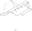
- the fixing assembly consists of fixing element 1, mounted on universal bracket 2.
- Bracket 2 is an element made of structural metal sheet by bending of a flat blank.
- the bracket comprises stem 21 and mounting arm 22, serving the purpose of a holder for mounting side casing 3 and fixing element 1.
- Bracket 2 is fastened via stem 21 on the side edges of the corner of sash frame 4.
- Stem 21 basically has a shape of an angle bar with mounting holes arranged for screws or other connecting media.
- Arm I 211 of stem 21, adjacent to upper sash member 41 of frame 4 constitutes a base for fixing holder 5 for a gas spring.
- Arm II 212 of stem 21 is adjacent to side sash frame member 42 of the sash and is fixed to it.
- Mounting arm 22 is a flat element bent aside of arm II outwards, in parallel to the sash plane.
- Fixing element 1 is made of plastic preferably by injection moulding and it basically serves the purpose of mounting and fixing of upper casing 6 at the casing's end using mounting slot 11.
- upper casing 6 is inserted longitudinally into mounting slot 11.
- the width of mounting slot 11 ensures that no capillary effect occurs, i.e. the effect of wetting of internal walls in narrow crevices by rainfall water utilising surface tension.
- the lack of the capillary effect in the point of contact of mounting slot 11 and upper casing 6 is ensured by tight connection of external surface 61 of upper casing 6 and upper wall 111 of mounting slot 11 in the area of their mutual contact after installation.
- Mounting slot 11 has a width not smaller than the sum of the thickness of upper casing metal sheet 6 being inserted to mounting slot 11, and the minimum distance between upper casing's 6 internal surface 62 and mounting slot's 11 lower wall 112, at which the capillary effect does not occur.
- the spacing of longitudinal ribs 12 is selected so as to the elastic deformation of upper casing 6 does not occur during the installation and operation.
- upper casing 6 or the fixing element may be deformed or damaged, increasing the risk of water penetration through the sealing strip under the surface of the casing elements.
- Possible small amount of water which may penetrate under the surface of upper casing 6 despite the sealing strip, is stopped on longitudinal ribs 12 or flows down to a water draining duct running along the edge of the insulating glass unit of the sash.
- Fixing element 1 is mounted on mounting arm 22 of bracket 2 and locked using a locking mechanism, having the following main components: pin 13 fixed in the internal surface of fixing element 1, locking hole 221 in mounting arm 22, and locking bolt 23 installed rotatably on mounting arm 22, on the side opposite to mounting surface 221 of mounting arm 22, in a plane parallel to the window plane.
- the pin 13 is inserted into locking hole 222.
- Pin 13 has a recess in the form of transverse groove 131, which, in the installed position of fixing element 1, is located on the height of locking bolt 23. After insertion of locking bolt 23 by rotary motion into the transverse groove, the possibility of slipping of pin 13 off from locking hole 222 is blocked, and an immovable mounting of the fixing element 1 on bracket 2 is secured.
- pin 13 has elastic elements 132, ensuring its pre-installation in locking hole 222 of mounting arm 22.
- Mounting arm 22 is additionally used for mounting of side casing's 3 upper edge made of metal sheet.
- Side casing 3 has transverse catch pawl 31, made by bending of metal sheet of the same blank, the pawl being inserted into rectangular through-hole 223 in mounting arm 22 during the installation.
- Transverse catch pawl 31 is protected from slipping off from through-hole 223 by the pressure of side edge 14 of fixing element 1, overlapped onto side casing 3 during installation.
- the set of two fixing assemblies on both ends of upper casing 6 provides a tight, rigid and separable connection of upper casing 6 and additionally side casings 3 at their upper ends.
- a possibility of a displacement of the upper casing in the mounting slots of the fixing elements is particularly desirable during the installation of the set and after the installation of the whole set for compensation of thermal elongation.
- Thermal elongation is compensated by structural expansion joints 113, being parts of mounting slots 11, and resulting from an incomplete insertion of upper casing 6. After the whole set of the casings is completed and fixed to the brackets, the distance between the bottoms of mounting slots 11 of symmetrically mounted fixing elements is longer than the length of upper casing 6.
Landscapes
- Engineering & Computer Science (AREA)
- Architecture (AREA)
- Civil Engineering (AREA)
- Structural Engineering (AREA)
- Door And Window Frames Mounted To Openings (AREA)
- Wing Frames And Configurations (AREA)
- Tents Or Canopies (AREA)
Applications Claiming Priority (1)
| Application Number | Priority Date | Filing Date | Title |
|---|---|---|---|
| PL410990A PL228671B1 (pl) | 2015-01-19 | 2015-01-19 | Okno dachowe lub wyłaz dachowy ze skrzydłem rozwieranym na zewnątrz z zespołem mocującym górny element osłonowy |
Publications (2)
| Publication Number | Publication Date |
|---|---|
| EP3045609A1 true EP3045609A1 (de) | 2016-07-20 |
| EP3045609B1 EP3045609B1 (de) | 2017-05-17 |
Family
ID=55182229
Family Applications (1)
| Application Number | Title | Priority Date | Filing Date |
|---|---|---|---|
| EP16151784.2A Not-in-force EP3045609B1 (de) | 2015-01-19 | 2016-01-19 | Ein dachfenster oder dachausstiegsfenster mit einem nach aussen offenbaren flügelrahmen mit einer befestigungsanordnung zur befestigung am oberen abdeckelement |
Country Status (2)
| Country | Link |
|---|---|
| EP (1) | EP3045609B1 (de) |
| PL (1) | PL228671B1 (de) |
Cited By (1)
| Publication number | Priority date | Publication date | Assignee | Title |
|---|---|---|---|---|
| EP3872277A1 (de) * | 2020-02-28 | 2021-09-01 | VKR Holding A/S | Dachfenster mit öffnungsbegrenzer zur begrenzung der öffnung eines dachfensters |
Citations (7)
| Publication number | Priority date | Publication date | Assignee | Title |
|---|---|---|---|---|
| PL212427A1 (pl) | 1978-12-30 | 1979-10-22 | Kieleckie Przed Produkcji Elem | Zestaw elementow prefabrykowanych i konstrukcja ich polaczen dla budownictwa jednorodzinnego |
| EP1533436A2 (de) * | 2003-11-21 | 2005-05-25 | VKR Holding A/S | Abdeck- und Abdichtungselement für Dachfenster |
| DE102009033938A1 (de) * | 2009-07-14 | 2011-01-20 | Roto Frank Ag | Wohndachfenster sowie Verfahren zum Befestigen eines Abdeckblechs |
| DE102009033941A1 (de) * | 2009-07-14 | 2011-01-27 | Roto Frank Ag | Wohndachfenster mit einem Flügelrahmen |
| EP2287416A2 (de) * | 2009-07-14 | 2011-02-23 | Roto Frank Ag | Wohndachfenster mit Befestigungsvorrichtung für ein Abdeckblech sowie Verfahren zur Befestigung des Abdeckblechs |
| EP2666926A1 (de) | 2012-05-25 | 2013-11-27 | Keystone Lintels Limited | Verdeckungsanordnung für ein Dachfenster |
| DE202012010009U1 (de) * | 2012-10-19 | 2014-01-20 | Vkr Holding A/S | Fenster mit Abschirmvorrichtung mit verbesserten Befestigungsvorrichtungen |
-
2015
- 2015-01-19 PL PL410990A patent/PL228671B1/pl unknown
-
2016
- 2016-01-19 EP EP16151784.2A patent/EP3045609B1/de not_active Not-in-force
Patent Citations (7)
| Publication number | Priority date | Publication date | Assignee | Title |
|---|---|---|---|---|
| PL212427A1 (pl) | 1978-12-30 | 1979-10-22 | Kieleckie Przed Produkcji Elem | Zestaw elementow prefabrykowanych i konstrukcja ich polaczen dla budownictwa jednorodzinnego |
| EP1533436A2 (de) * | 2003-11-21 | 2005-05-25 | VKR Holding A/S | Abdeck- und Abdichtungselement für Dachfenster |
| DE102009033938A1 (de) * | 2009-07-14 | 2011-01-20 | Roto Frank Ag | Wohndachfenster sowie Verfahren zum Befestigen eines Abdeckblechs |
| DE102009033941A1 (de) * | 2009-07-14 | 2011-01-27 | Roto Frank Ag | Wohndachfenster mit einem Flügelrahmen |
| EP2287416A2 (de) * | 2009-07-14 | 2011-02-23 | Roto Frank Ag | Wohndachfenster mit Befestigungsvorrichtung für ein Abdeckblech sowie Verfahren zur Befestigung des Abdeckblechs |
| EP2666926A1 (de) | 2012-05-25 | 2013-11-27 | Keystone Lintels Limited | Verdeckungsanordnung für ein Dachfenster |
| DE202012010009U1 (de) * | 2012-10-19 | 2014-01-20 | Vkr Holding A/S | Fenster mit Abschirmvorrichtung mit verbesserten Befestigungsvorrichtungen |
Cited By (1)
| Publication number | Priority date | Publication date | Assignee | Title |
|---|---|---|---|---|
| EP3872277A1 (de) * | 2020-02-28 | 2021-09-01 | VKR Holding A/S | Dachfenster mit öffnungsbegrenzer zur begrenzung der öffnung eines dachfensters |
Also Published As
| Publication number | Publication date |
|---|---|
| PL410990A1 (pl) | 2016-08-01 |
| EP3045609B1 (de) | 2017-05-17 |
| PL228671B1 (pl) | 2018-04-30 |
Similar Documents
| Publication | Publication Date | Title |
|---|---|---|
| EP2812522B1 (de) | Abstandhalterprofil für einen abstandhalterrahmen für eine isolierfenstereinheit mit zwischenraumelementen und isolierfenstereinheit | |
| PL174306B1 (pl) | Złącze stykowe | |
| US11038304B2 (en) | Holding frame for a plug connector and methods of populating same | |
| US4008552A (en) | Wall structure and elements therefor | |
| HUP0500792A2 (hu) | Retesz-oszlop szerkezet | |
| KR102135946B1 (ko) | 단열성이 향상된 프로젝트 창호 | |
| CN212053504U (zh) | 中间防护组件 | |
| KR102065295B1 (ko) | 단열성이 향상된 프로젝트 창호 | |
| EP3045609B1 (de) | Ein dachfenster oder dachausstiegsfenster mit einem nach aussen offenbaren flügelrahmen mit einer befestigungsanordnung zur befestigung am oberen abdeckelement | |
| CN112922218B (zh) | 防水构件之间密封垫、屋顶窗户防水装置、密封间隙方法 | |
| GB2534670A (en) | Fastening arrangement for mounting a decorative cover and/or a window guide on a vehicle door | |
| EP2581519A1 (de) | Befestigungseinheit für eine Anordnung eines Abschirmelements eines Dachfensterflügels | |
| KR101498224B1 (ko) | 와이퍼 블레이드 장치 | |
| CN112673180B (zh) | 连接装置和设置有这种连接装置的箱式设备 | |
| KR20200085294A (ko) | 베이 커넥터에 의해 상호 연결된 2개의 스위치 캐비닛 랙을 포함하는 장치 | |
| CN114108962A (zh) | 连接器装置和用于使屋顶窗装置防风雨的方法 | |
| WO2008131755A1 (en) | Window structure with a fitting for assembling the corners of the window sash | |
| EP2617593B1 (de) | Abdeckelement für Automobile | |
| KR0167594B1 (ko) | 창 또는 문의 프레임에 유리판 또는 충전 플레이트용 지지스트립을 고정시키기 위한 플라스틱 홀더 | |
| KR102386520B1 (ko) | 고성능 메탈 유닛 판넬 | |
| US11209295B2 (en) | Double hook snap fit for electronic housing | |
| GR1010630B (el) | Συνθετο προφιλ για πλαισιο ή φυλλο διαχωριστικου | |
| KR100820335B1 (ko) | 점검커버 부착구조 | |
| EP3433457A1 (de) | Kraftfahrzeugriegel mit abdeckung | |
| KR200313637Y1 (ko) | 렉산시트 지지용 프레임 |
Legal Events
| Date | Code | Title | Description |
|---|---|---|---|
| PUAI | Public reference made under article 153(3) epc to a published international application that has entered the european phase |
Free format text: ORIGINAL CODE: 0009012 |
|
| AK | Designated contracting states |
Kind code of ref document: A1 Designated state(s): AL AT BE BG CH CY CZ DE DK EE ES FI FR GB GR HR HU IE IS IT LI LT LU LV MC MK MT NL NO PL PT RO RS SE SI SK SM TR |
|
| AX | Request for extension of the european patent |
Extension state: BA ME |
|
| 17P | Request for examination filed |
Effective date: 20161227 |
|
| RBV | Designated contracting states (corrected) |
Designated state(s): AL AT BE BG CH CY CZ DE DK EE ES FI FR GB GR HR HU IE IS IT LI LT LU LV MC MK MT NL NO PL PT RO RS SE SI SK SM TR |
|
| GRAP | Despatch of communication of intention to grant a patent |
Free format text: ORIGINAL CODE: EPIDOSNIGR1 |
|
| RIC1 | Information provided on ipc code assigned before grant |
Ipc: E04D 13/03 20060101ALI20170207BHEP Ipc: E04D 13/035 20060101AFI20170207BHEP |
|
| GRAS | Grant fee paid |
Free format text: ORIGINAL CODE: EPIDOSNIGR3 |
|
| INTG | Intention to grant announced |
Effective date: 20170316 |
|
| RIN1 | Information on inventor provided before grant (corrected) |
Inventor name: STOKLOSA, LUKASZ Inventor name: MAJOCH, WACLAW |
|
| GRAA | (expected) grant |
Free format text: ORIGINAL CODE: 0009210 |
|
| AK | Designated contracting states |
Kind code of ref document: B1 Designated state(s): AL AT BE BG CH CY CZ DE DK EE ES FI FR GB GR HR HU IE IS IT LI LT LU LV MC MK MT NL NO PL PT RO RS SE SI SK SM TR |
|
| REG | Reference to a national code |
Ref country code: GB Ref legal event code: FG4D |
|
| REG | Reference to a national code |
Ref country code: CH Ref legal event code: EP |
|
| REG | Reference to a national code |
Ref country code: IE Ref legal event code: FG4D |
|
| REG | Reference to a national code |
Ref country code: AT Ref legal event code: REF Ref document number: 894604 Country of ref document: AT Kind code of ref document: T Effective date: 20170615 |
|
| REG | Reference to a national code |
Ref country code: DE Ref legal event code: R096 Ref document number: 602016000040 Country of ref document: DE |
|
| REG | Reference to a national code |
Ref country code: NL Ref legal event code: MP Effective date: 20170517 |
|
| REG | Reference to a national code |
Ref country code: LT Ref legal event code: MG4D |
|
| REG | Reference to a national code |
Ref country code: AT Ref legal event code: MK05 Ref document number: 894604 Country of ref document: AT Kind code of ref document: T Effective date: 20170517 |
|
| PG25 | Lapsed in a contracting state [announced via postgrant information from national office to epo] |
Ref country code: AT Free format text: LAPSE BECAUSE OF FAILURE TO SUBMIT A TRANSLATION OF THE DESCRIPTION OR TO PAY THE FEE WITHIN THE PRESCRIBED TIME-LIMIT Effective date: 20170517 Ref country code: LT Free format text: LAPSE BECAUSE OF FAILURE TO SUBMIT A TRANSLATION OF THE DESCRIPTION OR TO PAY THE FEE WITHIN THE PRESCRIBED TIME-LIMIT Effective date: 20170517 Ref country code: GR Free format text: LAPSE BECAUSE OF FAILURE TO SUBMIT A TRANSLATION OF THE DESCRIPTION OR TO PAY THE FEE WITHIN THE PRESCRIBED TIME-LIMIT Effective date: 20170818 Ref country code: HR Free format text: LAPSE BECAUSE OF FAILURE TO SUBMIT A TRANSLATION OF THE DESCRIPTION OR TO PAY THE FEE WITHIN THE PRESCRIBED TIME-LIMIT Effective date: 20170517 Ref country code: ES Free format text: LAPSE BECAUSE OF FAILURE TO SUBMIT A TRANSLATION OF THE DESCRIPTION OR TO PAY THE FEE WITHIN THE PRESCRIBED TIME-LIMIT Effective date: 20170517 Ref country code: FI Free format text: LAPSE BECAUSE OF FAILURE TO SUBMIT A TRANSLATION OF THE DESCRIPTION OR TO PAY THE FEE WITHIN THE PRESCRIBED TIME-LIMIT Effective date: 20170517 Ref country code: NO Free format text: LAPSE BECAUSE OF FAILURE TO SUBMIT A TRANSLATION OF THE DESCRIPTION OR TO PAY THE FEE WITHIN THE PRESCRIBED TIME-LIMIT Effective date: 20170817 |
|
| PG25 | Lapsed in a contracting state [announced via postgrant information from national office to epo] |
Ref country code: LV Free format text: LAPSE BECAUSE OF FAILURE TO SUBMIT A TRANSLATION OF THE DESCRIPTION OR TO PAY THE FEE WITHIN THE PRESCRIBED TIME-LIMIT Effective date: 20170517 Ref country code: PL Free format text: LAPSE BECAUSE OF FAILURE TO SUBMIT A TRANSLATION OF THE DESCRIPTION OR TO PAY THE FEE WITHIN THE PRESCRIBED TIME-LIMIT Effective date: 20170517 Ref country code: BG Free format text: LAPSE BECAUSE OF FAILURE TO SUBMIT A TRANSLATION OF THE DESCRIPTION OR TO PAY THE FEE WITHIN THE PRESCRIBED TIME-LIMIT Effective date: 20170817 Ref country code: NL Free format text: LAPSE BECAUSE OF FAILURE TO SUBMIT A TRANSLATION OF THE DESCRIPTION OR TO PAY THE FEE WITHIN THE PRESCRIBED TIME-LIMIT Effective date: 20170517 Ref country code: IS Free format text: LAPSE BECAUSE OF FAILURE TO SUBMIT A TRANSLATION OF THE DESCRIPTION OR TO PAY THE FEE WITHIN THE PRESCRIBED TIME-LIMIT Effective date: 20170917 Ref country code: RS Free format text: LAPSE BECAUSE OF FAILURE TO SUBMIT A TRANSLATION OF THE DESCRIPTION OR TO PAY THE FEE WITHIN THE PRESCRIBED TIME-LIMIT Effective date: 20170517 Ref country code: SE Free format text: LAPSE BECAUSE OF FAILURE TO SUBMIT A TRANSLATION OF THE DESCRIPTION OR TO PAY THE FEE WITHIN THE PRESCRIBED TIME-LIMIT Effective date: 20170517 |
|
| REG | Reference to a national code |
Ref country code: FR Ref legal event code: PLFP Year of fee payment: 3 |
|
| PG25 | Lapsed in a contracting state [announced via postgrant information from national office to epo] |
Ref country code: SK Free format text: LAPSE BECAUSE OF FAILURE TO SUBMIT A TRANSLATION OF THE DESCRIPTION OR TO PAY THE FEE WITHIN THE PRESCRIBED TIME-LIMIT Effective date: 20170517 Ref country code: DK Free format text: LAPSE BECAUSE OF FAILURE TO SUBMIT A TRANSLATION OF THE DESCRIPTION OR TO PAY THE FEE WITHIN THE PRESCRIBED TIME-LIMIT Effective date: 20170517 Ref country code: EE Free format text: LAPSE BECAUSE OF FAILURE TO SUBMIT A TRANSLATION OF THE DESCRIPTION OR TO PAY THE FEE WITHIN THE PRESCRIBED TIME-LIMIT Effective date: 20170517 Ref country code: CZ Free format text: LAPSE BECAUSE OF FAILURE TO SUBMIT A TRANSLATION OF THE DESCRIPTION OR TO PAY THE FEE WITHIN THE PRESCRIBED TIME-LIMIT Effective date: 20170517 Ref country code: RO Free format text: LAPSE BECAUSE OF FAILURE TO SUBMIT A TRANSLATION OF THE DESCRIPTION OR TO PAY THE FEE WITHIN THE PRESCRIBED TIME-LIMIT Effective date: 20170517 |
|
| REG | Reference to a national code |
Ref country code: DE Ref legal event code: R097 Ref document number: 602016000040 Country of ref document: DE |
|
| PG25 | Lapsed in a contracting state [announced via postgrant information from national office to epo] |
Ref country code: SM Free format text: LAPSE BECAUSE OF FAILURE TO SUBMIT A TRANSLATION OF THE DESCRIPTION OR TO PAY THE FEE WITHIN THE PRESCRIBED TIME-LIMIT Effective date: 20170517 Ref country code: IT Free format text: LAPSE BECAUSE OF FAILURE TO SUBMIT A TRANSLATION OF THE DESCRIPTION OR TO PAY THE FEE WITHIN THE PRESCRIBED TIME-LIMIT Effective date: 20170517 |
|
| PLBE | No opposition filed within time limit |
Free format text: ORIGINAL CODE: 0009261 |
|
| STAA | Information on the status of an ep patent application or granted ep patent |
Free format text: STATUS: NO OPPOSITION FILED WITHIN TIME LIMIT |
|
| 26N | No opposition filed |
Effective date: 20180220 |
|
| PG25 | Lapsed in a contracting state [announced via postgrant information from national office to epo] |
Ref country code: LU Free format text: LAPSE BECAUSE OF NON-PAYMENT OF DUE FEES Effective date: 20180119 |
|
| REG | Reference to a national code |
Ref country code: IE Ref legal event code: MM4A |
|
| REG | Reference to a national code |
Ref country code: BE Ref legal event code: MM Effective date: 20180131 |
|
| PG25 | Lapsed in a contracting state [announced via postgrant information from national office to epo] |
Ref country code: BE Free format text: LAPSE BECAUSE OF NON-PAYMENT OF DUE FEES Effective date: 20180131 |
|
| PG25 | Lapsed in a contracting state [announced via postgrant information from national office to epo] |
Ref country code: IE Free format text: LAPSE BECAUSE OF NON-PAYMENT OF DUE FEES Effective date: 20180119 |
|
| PGFP | Annual fee paid to national office [announced via postgrant information from national office to epo] |
Ref country code: DE Payment date: 20181221 Year of fee payment: 4 |
|
| PG25 | Lapsed in a contracting state [announced via postgrant information from national office to epo] |
Ref country code: MC Free format text: LAPSE BECAUSE OF FAILURE TO SUBMIT A TRANSLATION OF THE DESCRIPTION OR TO PAY THE FEE WITHIN THE PRESCRIBED TIME-LIMIT Effective date: 20170517 |
|
| REG | Reference to a national code |
Ref country code: CH Ref legal event code: PL |
|
| PG25 | Lapsed in a contracting state [announced via postgrant information from national office to epo] |
Ref country code: CH Free format text: LAPSE BECAUSE OF NON-PAYMENT OF DUE FEES Effective date: 20190131 Ref country code: LI Free format text: LAPSE BECAUSE OF NON-PAYMENT OF DUE FEES Effective date: 20190131 |
|
| PG25 | Lapsed in a contracting state [announced via postgrant information from national office to epo] |
Ref country code: MT Free format text: LAPSE BECAUSE OF NON-PAYMENT OF DUE FEES Effective date: 20180119 |
|
| PG25 | Lapsed in a contracting state [announced via postgrant information from national office to epo] |
Ref country code: TR Free format text: LAPSE BECAUSE OF FAILURE TO SUBMIT A TRANSLATION OF THE DESCRIPTION OR TO PAY THE FEE WITHIN THE PRESCRIBED TIME-LIMIT Effective date: 20170517 |
|
| PG25 | Lapsed in a contracting state [announced via postgrant information from national office to epo] |
Ref country code: PT Free format text: LAPSE BECAUSE OF FAILURE TO SUBMIT A TRANSLATION OF THE DESCRIPTION OR TO PAY THE FEE WITHIN THE PRESCRIBED TIME-LIMIT Effective date: 20170517 |
|
| PG25 | Lapsed in a contracting state [announced via postgrant information from national office to epo] |
Ref country code: HU Free format text: LAPSE BECAUSE OF FAILURE TO SUBMIT A TRANSLATION OF THE DESCRIPTION OR TO PAY THE FEE WITHIN THE PRESCRIBED TIME-LIMIT; INVALID AB INITIO Effective date: 20160119 Ref country code: MK Free format text: LAPSE BECAUSE OF NON-PAYMENT OF DUE FEES Effective date: 20170517 Ref country code: CY Free format text: LAPSE BECAUSE OF FAILURE TO SUBMIT A TRANSLATION OF THE DESCRIPTION OR TO PAY THE FEE WITHIN THE PRESCRIBED TIME-LIMIT Effective date: 20170517 |
|
| PG25 | Lapsed in a contracting state [announced via postgrant information from national office to epo] |
Ref country code: AL Free format text: LAPSE BECAUSE OF FAILURE TO SUBMIT A TRANSLATION OF THE DESCRIPTION OR TO PAY THE FEE WITHIN THE PRESCRIBED TIME-LIMIT Effective date: 20170517 |
|
| REG | Reference to a national code |
Ref country code: DE Ref legal event code: R119 Ref document number: 602016000040 Country of ref document: DE |
|
| PG25 | Lapsed in a contracting state [announced via postgrant information from national office to epo] |
Ref country code: DE Free format text: LAPSE BECAUSE OF NON-PAYMENT OF DUE FEES Effective date: 20200801 |
|
| PG25 | Lapsed in a contracting state [announced via postgrant information from national office to epo] |
Ref country code: SI Free format text: LAPSE BECAUSE OF NON-PAYMENT OF DUE FEES Effective date: 20180119 |
|
| PGFP | Annual fee paid to national office [announced via postgrant information from national office to epo] |
Ref country code: FR Payment date: 20230103 Year of fee payment: 8 |
|
| PGFP | Annual fee paid to national office [announced via postgrant information from national office to epo] |
Ref country code: GB Payment date: 20230105 Year of fee payment: 8 |
|
| P01 | Opt-out of the competence of the unified patent court (upc) registered |
Effective date: 20230419 |
|
| GBPC | Gb: european patent ceased through non-payment of renewal fee |
Effective date: 20240119 |
|
| PG25 | Lapsed in a contracting state [announced via postgrant information from national office to epo] |
Ref country code: GB Free format text: LAPSE BECAUSE OF NON-PAYMENT OF DUE FEES Effective date: 20240119 |
|
| PG25 | Lapsed in a contracting state [announced via postgrant information from national office to epo] |
Ref country code: FR Free format text: LAPSE BECAUSE OF NON-PAYMENT OF DUE FEES Effective date: 20240131 |
|
| PG25 | Lapsed in a contracting state [announced via postgrant information from national office to epo] |
Ref country code: GB Free format text: LAPSE BECAUSE OF NON-PAYMENT OF DUE FEES Effective date: 20240119 Ref country code: FR Free format text: LAPSE BECAUSE OF NON-PAYMENT OF DUE FEES Effective date: 20240131 |