EP3045621B1 - Barillet, clé et ébauche de clé - Google Patents
Barillet, clé et ébauche de clé Download PDFInfo
- Publication number
- EP3045621B1 EP3045621B1 EP15202589.6A EP15202589A EP3045621B1 EP 3045621 B1 EP3045621 B1 EP 3045621B1 EP 15202589 A EP15202589 A EP 15202589A EP 3045621 B1 EP3045621 B1 EP 3045621B1
- Authority
- EP
- European Patent Office
- Prior art keywords
- key
- locking
- housing
- blocking element
- cylinder
- Prior art date
- Legal status (The legal status is an assumption and is not a legal conclusion. Google has not performed a legal analysis and makes no representation as to the accuracy of the status listed.)
- Active
Links
Images



Classifications
-
- E—FIXED CONSTRUCTIONS
- E05—LOCKS; KEYS; WINDOW OR DOOR FITTINGS; SAFES
- E05B—LOCKS; ACCESSORIES THEREFOR; HANDCUFFS
- E05B29/00—Cylinder locks and other locks with plate tumblers which are set by pushing the key in
- E05B29/0013—Cylinder locks and other locks with plate tumblers which are set by pushing the key in with rotating plate tumblers
-
- E—FIXED CONSTRUCTIONS
- E05—LOCKS; KEYS; WINDOW OR DOOR FITTINGS; SAFES
- E05B—LOCKS; ACCESSORIES THEREFOR; HANDCUFFS
- E05B17/00—Accessories in connection with locks
- E05B17/20—Means independent of the locking mechanism for preventing unauthorised opening, e.g. for securing the bolt in the fastening position
- E05B17/2084—Means to prevent forced opening by attack, tampering or jimmying
-
- E—FIXED CONSTRUCTIONS
- E05—LOCKS; KEYS; WINDOW OR DOOR FITTINGS; SAFES
- E05B—LOCKS; ACCESSORIES THEREFOR; HANDCUFFS
- E05B19/00—Keys; Accessories therefor
-
- E—FIXED CONSTRUCTIONS
- E05—LOCKS; KEYS; WINDOW OR DOOR FITTINGS; SAFES
- E05B—LOCKS; ACCESSORIES THEREFOR; HANDCUFFS
- E05B19/00—Keys; Accessories therefor
- E05B19/0017—Key profiles
-
- E—FIXED CONSTRUCTIONS
- E05—LOCKS; KEYS; WINDOW OR DOOR FITTINGS; SAFES
- E05B—LOCKS; ACCESSORIES THEREFOR; HANDCUFFS
- E05B19/00—Keys; Accessories therefor
- E05B19/0017—Key profiles
- E05B19/0035—Key profiles characterized by longitudinal bit variations
-
- E—FIXED CONSTRUCTIONS
- E05—LOCKS; KEYS; WINDOW OR DOOR FITTINGS; SAFES
- E05B—LOCKS; ACCESSORIES THEREFOR; HANDCUFFS
- E05B19/00—Keys; Accessories therefor
- E05B19/0017—Key profiles
- E05B19/0041—Key profiles characterized by the cross-section of the key blade in a plane perpendicular to the longitudinal axis of the key
- E05B19/0052—Rectangular flat keys
-
- E—FIXED CONSTRUCTIONS
- E05—LOCKS; KEYS; WINDOW OR DOOR FITTINGS; SAFES
- E05B—LOCKS; ACCESSORIES THEREFOR; HANDCUFFS
- E05B21/00—Locks with lamelliform tumblers which are not set by the insertion of the key and in which the tumblers do not follow the movement of the bolt e.g. Chubb-locks
- E05B21/06—Cylinder locks, e.g. protector locks
- E05B21/066—Cylinder locks, e.g. protector locks of the rotary-disc tumbler type
Definitions
- the present invention relates to a locking cylinder with a cylinder housing, a disk housing rotatably mounted in the cylinder housing about a cylinder axis, a plurality of rotatably mounted adjusting disks arranged in the disk housing along the cylinder axis, each adjusting disk having a receiving opening for a key, and a locking element which is arranged in front of the adjusting disks as seen in a key insertion direction and is coupled to the disk housing in a rotationally fixed manner.
- a locking cylinder with rotating adjusting discs is also called a disc cylinder.
- Such a locking cylinder is in the DE 10 2011 015 314 A1
- a disc cylinder is also disclosed in the documents EP 0 712 979 B1 , WO 2014026166 A2 , US 4 195 503 , DE 20 2007 002 699 U1 , DE 198 44 593 C1 , WO 2014072570 A1 , DE 201 18 136 U1 and US 4 512 166 known.
- a locking cylinder 10 can have a cylinder housing 12 and a cylinder core which is mounted in the cylinder housing 12 so as to be rotatable about a cylinder axis and which is also referred to below as a disc housing 14.
- the rotary movement of the cylinder core or the disc housing 14 can be transmitted to a locking mechanism of a lock (not shown) via a coupling section 30 connected to the disc housing 14 and the lock can thus be unlocked or locked using the locking cylinder 10.
- rotatable adjusting discs 16 which are also referred to as locking discs, are accommodated one after the other along the cylinder axis.
- the adjusting discs 16 have respective central receiving openings 18, which together form a key channel 28 for inserting of a key 24 and which, in the example shown, have a rectangular cross-section.
- the adjusting disks 16 also have respective circumferential recesses in the form of locking recesses 20 for receiving a locking pin 22 which is aligned parallel to the cylinder axis.
- the locking pin 22 is accommodated in a slot 32 provided in the wall of the disk housing 14 in a radially movable manner.
- the locking pin 22 assumes a radially outer blocking position. In this blocking position, a section of the locking pin 22 engages in a locking pin receiving recess 34 provided on the inner wall of the cylinder housing 12, so that the disk housing 14 is blocked (apart from a slight torsional play) against a rotational movement relative to the cylinder housing 12.
- the adjusting disks 16 can be moved from their locking position to an unlocking position.
- the locking recesses 20 of all adjusting disks 16 are aligned with one another and radially with the locking pin 22, as seen in the direction of the cylinder axis.
- the locking pin 22 can then be moved radially inwards into its release position, in which it is located outside the locking pin receiving recess 34.
- the disk housing 14 is released for a rotational movement relative to the cylinder housing 12 and the disk housing 14 can be rotated further together with the adjusting disks 16 in the unlocking direction until the unlocking position is reached.
- a fixing recess 44 is also provided for receiving a core pin 46.
- the core pin 46 is aligned parallel to the cylinder axis and is accommodated in a slot provided in the wall of the disk housing 14 in a radially movable manner. In the closed position of the locking cylinder 10, the core pin 46 engages in the fixing recesses 44 of the adjusting disks 16 and thus prevents the adjusting disks 16 from rotating relative to one another when no key 24 is inserted.
- the key 24 assigned to the locking cylinder 10 has several differently angled notches 26 that correspond to different angular positions of the locking recesses 20 of the adjusting disks 16.
- the key 24 After being inserted into the key channel 28, the key 24 initially assumes a so-called initial position, from which the key 24 can be turned in the unlocking direction.
- the key 24 By turning the key 24 in the unlocking direction from the initial position, the key 24 initially reaches a so-called zero position, in which the core pin 46 can come out of engagement with the fixing recesses 44 of the adjusting disks 16 and the adjusting disks 16 are thus released for a rotary movement relative to the disk housing 14 in order to be able to align the locking recesses 20 of the adjusting disks 16 one after the other (so-called sorting).
- the adjusting disks 16 have a certain torsional play with respect to the respectively associated notch 26 of the key 24, the extent of which depends on the angular dimension of the respective notch 26, ie depending on the angular dimension of the notches 26, control sections of the respective notches 26 and corresponding control sections of the central receiving openings 18 of the associated respective adjusting disks 16 engage with one another at different times or in different angular positions during sorting.
- the entire rotation path of the key until the final sorting position of all setting disks 16 is reached is approximately 110°, i.e. after turning the key 24 by approximately 110°, all setting disks 16 are sorted and the locking recesses 20 are aligned radially with the locking pin 22.
- a grid of six different angular positions with equal spacing is provided for the possible angular positions of the locking recesses 20, with the angular distance between two locking recesses 20 adjacent in the grid being approximately 18°. Accordingly, there are six possible codings for each setting disk 16, whereby to set one of these codings, the respective setting disk 16 must be rotated by a certain angle from its zero position.
- a code "1" corresponds to a rotation of the adjusting disk 16 by approximately 20°
- an adjacent code “2” corresponds to a rotation of approximately 38°
- a code “6” corresponds to a rotation of approximately 110°, each measured from the zero position until the end of the sorting position is reached.
- the locking recesses 20 are accordingly arranged at an angular distance from the locking pin receiving recess 34 of the cylinder housing 12 that corresponds to the respective code when the adjusting disks 16 are in the zero position.
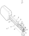
- the locking cylinder 100 according to the invention of Fig. 1 comprises a cylinder housing 12, a disk housing 14 rotatably mounted in the cylinder housing 12 about a cylinder axis and a plurality of rotatably mounted adjusting disks 16 arranged in the disk housing 14 along the cylinder axis, between each of which an intermediate disk 36, in particular one which is mounted in a floating manner, is arranged.
- the intermediate disks 36 can be secured against rotation by means of a stop device (not shown).
- Each adjusting disc 16 has on its outer circumference a locking recess 20 for receiving a locking pin 22 which is aligned parallel to the cylinder axis and is radially movable in a slot provided in the wall of the disc housing 14 (in Fig. 1 ).
- Each adjusting disk 16 also has, offset from the locking recess 20, at least one fixing recess 44 on its outer circumference for receiving a core pin 46 aligned parallel to the cylinder axis.
- the core pin 46 is also radially movable in a slot provided in the wall of the disk housing 14, which in Fig. 1 not shown.
- a front lifting disc 48 is provided - as seen in the direction of insertion A of the key 24 into the key channel 28 - which is rotatably mounted parallel to the adjusting discs 16 in the disc housing 14 and also has a central receiving opening 18 for the key 24.
- the front lifting disc 48 is thus located at the distal end of the disc housing 14 of the opening of the key channel 28.
- the front lifting disc 48 is positively coupled with respect to rotation to the key 24 inserted into the key channel 28. The front lifting disc 48 therefore always rotates when the key 24 is turned.
- a rear lifting disc 50 which is rotatably mounted in the disc housing 14 behind the package of adjusting discs 16 (ie at the proximal end of the disc housing 14) with respect to the insertion direction A.
- an intermediate disc 36 in particular a floating disc, is arranged between the adjacent adjusting disc 16 and the rear lifting disc 50, as Fig. 1 shows.
- the disk housing 14 is also closed with a cover 52, by which the disks 16, 36, 48, 50 are protected from falling out of the disk housing 14.
- the cover 52 also has a central receiving opening 18 for forming the key channel 28.
- the locking cylinder 100 is the Fig. 1 a separate control element 54 in the form of a control pin is provided.
- the control element 54 is provided at the level of the front lifting disc 48 and thus in the insertion direction A of the key 24 adjacent to the locking pin 22 and is arranged radially movable in a separate slot of the disc housing 14 or in the same slot in which the locking pin 22 is arranged.
- the control element 54 can also be designed as a ball, for example.
- the front lifting disc 48 has a control recess 70 ( Fig. 5, 8 , 11 ) and a further tax exemption circumferential recess 108 ( Fig. 14 , 17, 20, 23 ) for receiving the control element 54.
- a first locking element formed by a so-called sliding lock 56 and a second locking element formed by a so-called rotary sliding lock 58 are arranged in front of the disk housing 14 (i.e. offset distally) within the same plane, which are mounted so as to be movable in a translational (i.e. linear) manner in a normal plane to the cylinder axis parallel to a radial direction with respect to the cylinder axis.
- the disc housing 14 also has a receiving opening 18 at its front end, seen in the insertion direction A of the key 24, through which a tip 60 of the key 24 (cf. Fig. 1 and 2 ) when the key is inserted into the keyway 28.
- a tip 60 of the key 24 cf. Fig. 1 and 2
- the slide lock 56 and the rotary slide lock 58 can be actuated via the key tip 60.
- An attachment 62 is placed on the front end of the disc housing 14 as seen in the key insertion direction A.
- the attachment 62 serves as a holder and translational guide for the sliding lock 56 and the rotary sliding lock 58 as well as a connecting link to a Fig. 1 not shown lock mechanism so that it can be operated by turning the disc housing (see the coupling section 30 in Fig. 25 ).
- clamps 64 are provided with which the attachment 62 can be clamped to the disk housing 14, in particular on opposite sides.
- the in Fig. 2a The key 24 shown has several differently angled notches 26, which in a manner known per se have different angular positions the locking recesses 20 and the fixing recesses 44 of the adjusting disks 16.
- the adjusting disks 16 have a certain torsional play with respect to the respective associated notch 26 of the key 24, the extent of which depends on the angular dimension of the respective notch 26.
- control sections (flanks) of the respective notches 26 and corresponding control sections (inner walls) of the central receiving openings 18 of the associated respective adjusting disks 16 engage at different times and in accordance with the coding provided in the respective notch 26, as already described above with reference to the Fig. 25 and 26 was described.
- the front lifting disc 48 and the rear lifting disc 50 have the coding "6", so that the two lifting discs 48 and 50 are forcibly coupled to the key 24 with respect to rotation.
- the Fig. 3 shows a longitudinal section through the disc housing 14 and in particular the two lifting discs 48, 50 with the adjusting discs 16 in between, the locking pin 22, the core pin 46, the control element 54 as well as the sliding lock 56 which interacts with the key tip 60 and the rotary sliding lock 58 which also interacts with the key tip 60.
- Fig. 4 to 6 represent the situation with the key removed, which is also referred to as the initial position, in different viewing planes (each looking in the opposite direction to the key insertion direction A).
- Fig. 4 shows a cross-section through the locking cylinder at the level of the rotary slide lock 58 and the slide lock 56.
- the rotary slide lock 58 assumes a locking position, since the rotary slide lock 58 is in a position on the inner wall of the cylinder housing 12 provided rotary slide lock receiving recess 66.
- the slide lock 56 assumes a locking position because the slide lock 56 engages in a slide lock receiving recess 68 provided on the inner wall of the cylinder housing 12.
- the rotary slide lock 58 and the slide lock 56 are each pre-tensioned in the direction of their respective locking position by means of a spring (not shown).
- the slide lock 56 and the rotary slide lock 58 fulfill different functions because they are effective as locking elements at different times.
- Fig. 7 shows the same cross-sectional plane as Fig. 4 , but with the key 24 inserted but not yet turned, i.e. in the so-called initial position. How Fig. 7 shows, is done by inserting the key 24 into the key channel 28 (cf. Fig. 1 ) the sliding lock 56 is actuated by the key tip 60 in such a way that the sliding lock 56 is forced out of the sliding lock receiving recess 68 in a direction transverse to the cylinder axis and is thereby moved from the locking position into a release position.
- a locking position in the initial position according to Fig.
- Fig. 7 is simply by inserting the key 24 into the key channel 28 (cf. Fig. 1 ) the rotary slide lock 58 is not yet actuated by the key tip 60. In the initial position with the key 24 inserted, the rotary slide lock 58 is therefore still in the locking position and therefore engages in the rotary slide lock receiving recess 66 of the cylinder housing 12.
- the Fig. 5 shows in the initial position a cross section through the locking cylinder 100 of Fig. 1 at the level of the front lifting disc 48.
- the control element 54 is arranged in a slot provided in the disc housing 14 and engages in the control recess 70 of the front lifting disc 48 in the starting position. The control element 54 thereby fixes the disc housing 14 and the front lifting disc 48 against each other.
- the core pin 46 is also arranged in a slot of the disc housing 14 and engages in a fixing recess 72 which is formed on the outer circumference of the front lifting disc 48.
- the core pin 46 thus also fixes the front lifting disc 48 relative to the disc housing 14.
- several fixing recesses 72 lying next to one another in the circumferential direction of the front lifting disc 48 are provided on the outer circumference of the front lifting disc 48, which can also serve as chatter marks when the front lifting disc 48 is rotated relative to the core pin 46.
- the Fig. 8 shows the same cross-sectional plane as the Fig. 5 , but in the initial position with the key 24 inserted and not yet turned. As a comparison of the Fig. 5 and 8 shows, inserting the key 24 into the locking cylinder does not cause any change in the cross-sectional plane shown.
- the Fig. 6 shows a cross section through the locking cylinder of the Fig. 1 at the height of the rear lifting disc 50 in the starting position.
- the core pin 46 also engages in a fixing recess 72 of the rear lifting disc 50 in the starting position, whereby - as with the front lifting disc 48 - several fixing recesses 72 lying next to one another in the circumferential direction are also formed on the outer circumference of the rear lifting disc 50.
- the core pin 46 also engages in corresponding fixing recesses 44 (cf. Fig. 1 ), which are in the adjustment discs 16 (and preferably also in the intermediate disks 36) are provided (cf.
- the core pin 46 in the starting position also fixes the adjusting disks 16 against rotation relative to the disk housing 14.
- the adjusting disks 16 cannot therefore be individually rotated relative to the disk housing 14 in the starting position, which already provides effective protection against picking.
- unintentional rotation of the adjusting disks 16 and the lifting disks 48, 50 can be prevented, which can ensure that the key 24 can be inserted into the key channel 28.
- Fig. 6 also shows, the (in axial alignment with the control element 54 according to Fig. 5 arranged) locking pin 22 is arranged in a slot of the disk housing 14 and, in the initial position, engages in a locking pin receiving recess 74 formed on the inner wall of the cylinder housing 12.
- the locking pin 22 rests on the outside of the rear lifting disk 50, so that the locking pin 22, in contrast to the core pin 46, does not fix the lifting disk 50 to the disk housing 14.
- the Fig. 9 shows the same cross-sectional plane as the Fig. 6 , but in the initial position with the key now inserted but not yet turned. As can be seen by comparing Fig. 6 and Fig. 9 As can be seen, no change is caused in the cross-sectional plane shown by the insertion of the key.
- the Fig. 10 shows the same cross-sectional plane as the Fig. 4 and 7 , while the key 24 is turned to a so-called zero position, and the Fig. 13 shows the same cross-sectional plane again, while the key 24 is turned into a so-called sorting end position.
- the Fig. 11 the same cross-sectional plane as the Fig. 5 and 8 in the zero position
- the Fig. 14 shows again the same cross-sectional plane as the Fig. 5, 8 and 11 in the final sorting position.
- the Fig. 12 shows the same cross-sectional plane as the Fig. 6 and 9 in the zero position
- Fig. 15 shows again the same cross-sectional plane as the Fig. 6, 9 and 12 in the final sorting position.
- the key 24 is rotated so far in relation to the initial position along an unlocking direction D that the disk housing 14 is initially locked against further rotational movement and now the adjusting disks 16 are released for rotational movement relative to the disk housing 14 (so-called sorting).
- sorting the sorting process of the adjusting disks 16 is completed, so that the locking recesses 20 of all adjusting disks 16 are aligned with one another.
- the fixing recesses 44 of all adjusting disks 16 are aligned with one another as seen in the direction of the cylinder axis.
- the locking element formed by the rotary slide lock 58 initially locks the disk housing 14 in the zero position in order to fix the disk housing 14 relative to the cylinder housing 12 during the sorting of the adjusting disks 16.
- the rotary slide lock 58 is only moved from the locking position to the release position when the final sorting position is reached, whereby the rotary slide lock 58 is translationally displaced radially inwards.
- the rotary slide lock 58 is thus disengaged from the rotary slide lock receiving recess 66 of the cylinder housing 12. This displacement of the rotary slide lock 58 into the release position, which is delayed compared to the displacement of the slide lock 56, is brought about by a rotary movement of the key 24.
- the rotary slide lock 58 has an output flank 78 which does not come into contact with the tip 60 of the key 24 when the key 24 is inserted, i.e. in the initial position.
- a drive flank 80 (cf. Fig. 2a and 2b ) is formed.
- the output flank 78 of the rotary slide lock 58 and the drive flank 80 at the tip 60 of the key 24 are adapted for this purpose and interact in such a way that the two flanks 78, 80 only come into contact with one another when the key 24 is moved in the unlocking direction D from the initial position (cf. Fig. 7 ) initially to the zero position (cf. Fig. 10 ) and then rotated until shortly before the final sorting position.
- the rotary slide lock receiving recess 66 on the inner wall of the cylinder housing 12 is larger in the circumferential direction or in the direction of rotation D than the extent of the end of the rotary slide lock 58 protruding into the rotary slide lock receiving recess 66 in the circumferential direction.
- the rotary slide lock 58 thus has a torsional play relative to the cylinder housing 12 in its locking position.
- the torsional play consists of the initial position and the starting position according to Fig. 4 or Fig. 7 in unlocking direction D. After inserting the key 24, the torsional play must first be overcome by moving the key 24 and thus the disc housing 14 together with the rotary slide lock 58 into the zero position according to Fig.
- the rotary slide lock receiving recess 66 which is formed on the inner wall of the cylinder housing 12, has a first stop surface 86 for the end of the rotary slide lock 58 protruding into the rotary slide lock receiving recess 66.
- the end of the rotary slide lock 58 comes to rest on the first stop surface 86 when the key 24 is moved in the unlocking direction D from the initial position according to Fig. 7 is rotated to the zero position, as Fig. 10 shows.
- the first stop surface 86 can block further rotation of the disk housing 14 in the unlocking direction D, in particular if an attempt is made to operate the locking cylinder 100 with an unsuitable, "wrong" key, via the key tip of which the rotary slide lock 58 cannot be operated during the rotation of the key from the zero position to the final sorting position and can thereby be brought out of engagement with the rotary slide lock receiving recess 66.
- the rotary slide lock receiving recess 66 of the cylinder housing 12 also has a second stop surface 88 opposite the first stop surface 86, against which the end of the rotary slide lock 58 protruding into the rotary slide lock receiving recess 66 rests when the key is removed (cf. the Fig. 4 and 7 ).
- the second stop surface 88 blocks rotation of the rotary slide lock 58 and thus of the disk housing 14 against the unlocking direction D beyond the starting position.
- the starting position is thus defined against the unlocking direction D in particular by the stop of the rotary slide lock 58 on the second stop surface 88 of the cylinder housing 12 and in the unlocking direction D by the stop of the slide lock 56 on a third stop surface 90 of the cylinder housing 12, which delimits the slide lock receiving recess 68 in the unlocking direction D.
- the key 24 for operating the rotary slide lock 58 has the tip 60 on its shaft 81, which interacts with the rotary slide lock 58 when the key 24 is turned.
- the shaft 81 has two broad sides 84 and two narrow sides 82
- the key or shaft tip 60 accordingly has two broad sides 84a, two narrow sides 82a and one end face 85.
- Each broad side 84 of the shaft 81 has a plane 92 in which the outer surface of the relevant broad side 84 lies.
- the plane 92 thus covers the outer elements or surfaces of the broad side 84 of the shaft 81.
- Recesses, such as one or more longitudinal grooves in the broad side 84, are thus set back from the plane 92 towards the key axis.
- Fig. 2a only the level 92 of the upper broadside 84 in the illustration is shown.
- a flattening 94 is provided relative to the respective plane 92 of the corresponding shaft broad side 84.
- the flattening 94 of the upper broad side 84a is rotationally symmetrical by 180° relative to the key longitudinal axis to the corresponding flattening on the lower broad side 84a of the key of the Fig. 2a designed so that the key 24 can be used as a reversible key.
- the respective flattening 94 extends in the transverse direction, ie viewed transversely to the key axis, only over a part of the corresponding broad side 84a of the shaft tip 60, while another part of the corresponding broad side 84a of the shaft tip 60 forms the said drive flank 80 for actuating the rotary slide lock 58 and preferably lies in the plane 92 of the corresponding shaft broad side 84.
- the drive flank 80 moves from the zero position to the final sorting position with the output flank 78 of the rotary slide lock when the key 24 is turned. 58 in order to move the rotary slide lock 58 into the release position (cf. Fig. 13 ).
- the broad side 84a of the shaft tip 60 is set back with respect to the plane 92 of the broad side 84 of the shaft 81.
- the flattening 94 extends in the longitudinal direction, ie viewed in the direction of the key axis, over the entire broad side 84a of the shaft tip 60. In the transverse direction, however, the flattening 94 extends over a part of the broad side 84a, which takes up approximately 70% of the width of the broad side 84a of the shaft tip 60, while the drive flank 80 extends in the transverse direction only over approximately 30% of the width of the broad side 84a.
- the respective flattening 94 is - as in Fig. 2a and 2b shown - with respect to the plane 92 of the corresponding shaft broadside 84 is inclined in sections, wherein the inclination angle between the respective flattening 94 and the plane 92 is open in a direction transverse to the key longitudinal axis (and not along the key longitudinal axis).
- the respective flattening 94 is inclined relative to the corresponding shaft broadside 84 with respect to an axis that runs along or parallel to the key longitudinal axis.
- the flattened area 94 can have a smooth surface, so that no depressions (such as a hole) and/or elevations are formed on it. Alternatively, however, at least one hole and/or at least one elevation can be provided on the flattened area 94 (not shown).
- the flattened area 94 can in particular run parallel, or obliquely, or in sections parallel and in sections obliquely to the plane 92 of the corresponding shaft broad side 84.
- the flattened area 94 can, for example, be inclined relative to the plane 92 of the shaft broad side 84 by an angle that can be in the range between 2 and 25 degrees.
- the flattened area 94 can also have an at least slightly curved contour when viewed transversely to the key axis. In the embodiment according to Fig. 2b the respective flattening 94 is concavely curved in a direction transverse to the key axis.
- the narrow sides 82a of the shaft tip 60 run towards each other in a roof-like manner towards the front side 85.
- the narrow sides 82a thus run tapered obliquely towards the front side 85.
- the narrow sides 82a of the shaft tip 60 taper at the end of the shaft tip 60 facing away from the front side 85, so that the tip 60 is separated from the rest of the shaft 81 by a circumferential notch 96 on the narrow sides 82a.
- This notch 96 can be used to insert a tool during the transition from the starting position ( Fig. 4 ) to the starting position ( Fig. 7 ) the sliding lock 56 engages.
- second circumferential notch 98 may be formed on the narrow sides 92 of the shaft 81, into which a locking disk 102 associated with the second notch 98 engages when the key 24 is turned (cf. Fig. 1 ). If an unsuitable key without a corresponding second notch 98 is used, the locking disk 102 can block rotation of the key in the locking cylinder 100. The security against manipulation can thus be increased.
- control element 54 in the zero position comes out of engagement with the control recess 70 of the front lifting disc 48 by bringing the control element 54 radially outward into engagement with a control element receiving recess 104 which is formed on the inside of the cylinder housing 12.
- the disc housing 14 is fixed against rotation on the cylinder housing 12, whereas the fixation of the front lifting disc 48 on the disc housing 14 caused by the control element 54 is canceled.
- the core pin 46 is also pushed radially outwards from the fixing recess 72 of the front lifting disc 48 in the zero position, so that the core pin 46 comes into engagement with a core pin receiving recess 106 provided on the inner wall of the cylinder housing 12. A blockage of the rotation of the front lifting disc 48 relative to the disc housing 14 caused by the core pin 46 is thus removed.
- the core pin 46 fixes the disc housing 14 against rotation on the cylinder housing 12 due to the engagement of the core pin 46 in the core pin receiving recess 106.
- the core pin 46 also comes out of engagement with the corresponding fixing recess 72 with respect to the rear lifting disc 50 and into engagement with the core pin receiving recess 106, which can extend, for example, in the form of an elongated groove over substantially the entire length of the inner wall of the cylinder housing 12. The fixation of the rear lifting disc 50 with respect to the disc housing 14 caused by the core pin 46 is canceled.
- the core pin 46 also comes out of engagement with the fixing recesses 44 of the adjusting disks 16, so that in the zero position the blocking of the adjusting disks 16 relative to the disk housing 14 is removed and the adjusting disks 16 are now released for sorting.
- This sorting is now carried out, as explained, by the interaction of the notches 26 of the key 24 with the inner walls or boundaries of the receiving openings 18 of the adjusting disks 16.
- Fig. 13 shows the final sorting position after the rotary slide lock 58 has been moved into the release position by a rotary movement of the key tip 60 as explained.
- the front lifting disc 48 is rotated in the final sorting position such that the circumferential recess 108 provided on the outer circumference of the front lifting disc 48 is radially aligned with the control element 54.
- the fixing recess 72 is radially aligned with the core pin 46.
- the adjusting disks 16 are sorted.
- the locking recesses 20 of the adjusting disks 16 (cf. Fig. 1 ) and accordingly also the locking recess 20 of the rear lifting disc 50 are aligned with each other in the direction of the cylinder axis and arranged radially inward with respect to the locking pin 22.
- the Fixing recesses 44 of the adjusting discs 16 in the same way as the fixing recess 72 of the rear lifting disc 50 according to Figure 15 , arranged radially inward with respect to the core pin 46 and aligned with one another when viewed in the direction of the cylinder axis.
- FIGS 16, 19 and 22 show the same cross-sectional plane as the Fig. 4, 7 , 10 and 13 However, the Fig. 16 the key 24 is in a position opposite to the sorting end of the Fig. 13 further rotated in unlocking direction D, the so-called unlocking position. Fig. 19 the key 24 is in a so-called unlocked position, and when Fig. 22 the key 24 is in the unlocked position.
- the Fig. 17, 20 and 23 show the same cross-sectional plane as the Fig. 5, 8 , 11 and 14 .
- the Fig. 17 to the unlocked position, whereas the Fig. 20 the unlocked position and the Fig. 23 the unlocking position.
- the Fig. 18, 21 and 24 the same cross-sectional plane as the Fig. 6, 9 , 12 and 15 .
- the Fig. 18 shows the situation in the unlocked position, whereas the Fig. 21 shows the unlocked position.
- the Fig. 24 also shows the situation in the unlocked position.
- both the control element 54 and the core pin 46 are initially pushed radially inwards.
- the core pin 46 thereby comes into engagement with the fixing recess 72 of the front lifting disc 48 or the rear lifting disc 50, which is located radially inside the core pin 46.
- the control element 54 comes into engagement with the circumferential recess 108 of the front lifting disc 48 and disengages from the control element receiving recess 104 formed in the cylinder housing 12.
- the front lifting disc 48 has a stop 110 on the outer circumference, which when the sorting end position is reached according to the Figure 14 comes into contact with a counter stop 112 provided on the disc housing 14 (a corresponding stop is also provided on the rear lifting disc 50).
- the disk housing 14 presses the core pin 46 against a core pin guide bevel 114, which limits the core pin receiving recess 106 as seen in the unlocking direction D and by means of which the core pin 46 is pressed into the fixing recesses 72 of the lifting disks 48, 50 and into the fixing recesses 44 of the adjusting disks 16 at a precisely defined angle of rotation (cf. Fig. 17 and 18 ).
- the locking pin receiving recess 74 of the cylinder housing 12 in the final sorting position offers a greater torsional play (in particular in the unlocking direction D) compared to the core pin receiving recess 106 and the control element receiving recess 104, so that the locking pin 22 is initially not pushed radially inwards into the locking recess 20 of the rear lifting disk 50 and accordingly into the locking recesses 20 of the adjusting disks 16 when the disk housing 14 is rotated further in the unlocking direction D from the final sorting position (cf. Fig. 18 ).
- the locking pin 22 only comes into contact with a locking pin guide bevel 118 that limits the locking pin receiving recess 74 in the unlocking direction D when the unlocking position is reached.
- the locking pin guide bevel 118 pushes when the disc housing 14 is rotated further from the unlocking position to the unlocked position according to Fig. 21 the locking pin 22 radially inwards so that the locking pin 22 engages with the locking recesses 20 of the rear lifting disc 50 and the adjusting discs 16.
- the key 24 can then be moved together with the disc housing 14 and the discs 16, 48, 50 into the unlocking position according to the Fig. 22, 23 and 24 be rotated further in order to actuate a locking mechanism by means of the attachment 62, as explained.
- the core pin 46 firstly engages the fixing recesses 72 of the lifting disks 48, 50 and the fixing recesses 44 of the adjusting disks 16 (cf. Fig. 1 ) and thereby fixes the adjusting disks 16 relative to each other and to the disk housing 14, and that only then (due to a further rotation of the disk housing 14) the locking pin 22 penetrates into the locking recesses 20 in order to lock the disk housing 14 for a further Twisting to release it into the unlocking position.
- the locking pin 22 cannot be pushed radially inwards with the aid of the locking pin guide bevel 118 at a time when the adjusting disks 16 can still be rotated separately (e.g. using a picking tool). This prevents the respective coding of the individual adjusting disks 16 from being scanned.
- the front lifting disc 48 has a second stop 120 on its outer circumference, which is actuated when the front lifting disc 48 is turned back from the end sorting position (cf. Fig. 14 ) against the unlocking direction D, i.e. in the locking direction, when the zero position is reached, comes into contact with a second counter-stop 122 provided on the disc housing 14 (cf. Fig. 11 ).
- a corresponding stop is also provided on the rear lifting disc 50.
Landscapes
- Physics & Mathematics (AREA)
- Electromagnetism (AREA)
- Lock And Its Accessories (AREA)
Claims (15)
- Cylindre de fermeture comprenantun boîtier de cylindre (12),un boîtier à disques (14) logé dans le boîtier de cylindre (12) de manière à pouvoir tourner autour d'un axe de cylindre,plusieurs disques de réglage (16) disposés dans le boîtier à disques (14) le long de l'axe du cylindre et montés de façon mobile en rotation, chaque disque de réglage (16) présentant une ouverture de réception (18) pour une clé (24), etun élément de blocage (58) qui, vu dans un sens d'insertion de clé (A), est disposé en amont des disques de réglage (16) et est couplé solidairement en rotation au boîtier à disques (14),dans lequell'élément de blocage (58) est conçu pour occuper une position de blocage dans laquelle l'élément de blocage (58) bloque le boîtier à disques (14) à l'encontre d'une rotation par rapport au boîtier de cylindre (12) du fait que l'élément de blocage (58) s'engage dans un renfoncement de réception (66) du boîtier de cylindre (12),caractérisé en ce quedans la position de blocage, l'élément de blocage (58) présente un jeu de rotation par rapport au boîtier de cylindre (12), l'élément de blocage (58) étant en outre conçu pour, une fois que la clé (24) est insérée dans le cylindre de fermeture, par rotation de la clé insérée (12) dans un sens de déverrouillage (D), être déplacé de la position de blocage à une position de déblocage uniquement après avoir surmonté le jeu de rotation, position de déblocage dans laquelle l'élément de blocage (58) est dégagé du renfoncement de réception (66).
- Cylindre de fermeture selon la revendication 1,
caractérisé en ce que l'élément de blocage (58) présente un flanc mené (78) qui coopère avec un flanc menant (80) formé au niveau de la pointe (60) de la clé (24), de telle sorte que l'élément de blocage (58) est déplacé de la position de blocage à la position de déblocage par rotation de la clé (24) dans le sens de déverrouillage (D). - Cylindre de fermeture selon la revendication 2,
caractérisé en ce que
le flanc mené (78) de l'élément de blocage (58) et le flanc menant (80) au niveau de la pointe (60) de la clé (24) sont adaptés pour que les deux flancs (78, 80) ne viennent en contact l'un avec l'autre que lorsque la clé (24) a été tournée au moins vers une première position de rotation à partir d'une position initiale que la clé (24) occupe après avoir été insérée dans le cylindre de fermeture (100). - Cylindre de fermeture selon la revendication 3,
caractérisé en ce que
le flanc mené (78) de l'élément de blocage (58) et le flanc menant (80) au niveau de la pointe (60) de la clé (24) sont adaptés pour que l'élément de blocage (58) se déplace de la position de blocage vers la position de déblocage pendant que la clé (24) est tournée de la première position de rotation dans le sens de déverrouillage (D) vers une deuxième position de rotation. - Cylindre de fermeture selon l'une des revendications 2 à 4,
caractérisé en ce que
les ouvertures de réception (18) des disques de réglage (26) forment un canal à clé (28) dans une position initiale du cylindre de fermeture (100), le flanc mené (78) de l'élément de blocage (58) étant disposé à l'extérieur du canal à clé (28). - Cylindre de fermeture selon l'une des revendications précédentes, caractérisé en ce que
la pointe (60) de la clé (24) a une forme de section transversale avec deux petits côtés (82a) et deux grands côtés (84a) qui sont plus longs que les petits côtés (82a), l'élément de blocage (58) pouvant être entraîné au moyen de l'un des grands côtés (82a) de la pointe (60) de la clé pour se déplacer de la position de blocage vers la position de déblocage. - Cylindre de fermeture selon la revendication 1,
caractérisé en ce quelors de la rotation de la clé (24) dans le sens de déverrouillage (D), l'élément de blocage (58) peut être entraîné en rotation d'une position initiale que la clé occupe après avoir été insérée dans le cylindre de fermeture (100), vers une première position de rotation de telle sorte que l'élément de blocage (58) demeure d'abord dans la position de blocage ;
ou en ce quele renfoncement de réception (66) du boîtier de cylindre (12) présente une première surface de butée (86) pour une extrémité de l'élément de blocage (58) pénétrant dans le renfoncement de réception (66), surface sur laquelle l'extrémité de l'élément de blocage (58) vient en appui lorsque la clé (24) a été tournée dans le sens de déverrouillage (D) d'une position initiale que la clé (24) occupe après avoir été insérée dans le cylindre de fermeture (100), vers une première position de rotation, la première surface de butée (86) empêchant une poursuite de la rotation de l'élément de blocage (58) dans le sens de déverrouillage (D). - Cylindre de fermeture selon la revendication 7,
caractérisé en ce que
le renfoncement de réception (66) présente une deuxième surface de butée (88) pour l'extrémité de l'élément de blocage (58) pénétrant dans le renfoncement de réception, sachant que, lorsque la clé (24) est retirée du cylindre de fermeture (100), l'extrémité de l'élément de blocage (58) est en appui contre la deuxième surface de butée (88) et la deuxième surface de butée (88) empêche une rotation de l'élément de blocage (58) dans le sens opposé au sens de déverrouillage (D). - Cylindre de fermeture selon l'une des revendications précédentes, caractérisé en ce quel'élément de blocage (58) est monté de manière à pouvoir être décalé en ligne droite dans un plan normal à l'axe du cylindre ;
et/ou en ce quel'élément de blocage (58) est précontraint en direction de la position de blocage ;
et/ou en ce queun autre élément de blocage (56), vu dans le sens d'insertion de la clé (A), est disposé en amont des disques de réglage (16) et est couplé solidairement en rotation au boîtier à disques (14), l'autre élément de blocage (56) occupant une position de blocage lorsque la clé (24) est retirée du cylindre de fermeture (100), dans laquelle l'autre élément de blocage (56) s'engage dans un autre renfoncement de réception (68) du boîtier de cylindre (12), et l'autre élément de blocage (56) peut être dégagé de l'autre renfoncement de réception (68) et donc être déplacé vers une position de déblocage par l'insertion de la clé (24) dans le cylindre de fermeture (100). - Clé ou ébauche de clé pour un cylindre de fermeture (100) selon l'une des revendications précédentes, comprenant une tige (81) dont la pointe (60) est adaptée pour coopérer avec un élément de blocage (58) prévu dans le cylindre de fermeture (100), la tige (81) présentant deux grands côtés (84) et deux petits côtés (82), et la pointe de tige (60) présentant deux grands côtés (84a), deux petits côtés (82a) et un côté frontal (85), caractérisée en ce que
sur au moins un grand côté (84a) de la pointe de tige (60), il est prévu un méplat (94) qui est décalé en arrière par rapport à un plan (92) du grand côté (84) de la tige (60). - Clé ou ébauche de clé selon la revendication 10,
caractérisée en ce quele méplat (94) est formé le long de l'axe de la clé sur tout le grand côté (84a) de la pointe de tige (60) ;
et/ou en ce quedans une direction transversale à l'axe de la clé, le méplat (94) s'étend uniquement sur une partie du grand côté (84a) de la pointe de tige (60), tandis qu'une autre partie du grand côté (84a) de la pointe de tige (60) se trouve dans le plan (92) du grand côté (84) de la tige (60). - Clé ou ébauche de clé selon la revendication 10 ou 11,
caractérisée en ce quele méplat (94) est parallèle au plan (92) du grand côté (84) de la tige (81) ; oule méplat (94) est incliné par rapport au plan (92) du grand côté (84) de la tige (81) ; oule méplat (94) est en partie parallèle et en partie incliné par rapport au plan (92) du grand côté (84) de la tige (81). - Clé ou ébauche de clé selon l'une des revendications 10 à 12, caractérisée en ce quele méplat (94) est incliné d'un angle prédéterminé par rapport au plan (92) du grand côté (84) de la tige (81), l'angle étant de préférence compris dans une plage de 2 à 25 degrés, plus préférentiellement dans une plage de 5 à 20 degrés, et encore plus préférentiellement dans une plage de 10 à 15 degrés ;
et/ou en ce queun méplat respectif (94) est prévu sur chacun des deux grands côtés (84a) de la pointe de tige (60), les deux méplats (94) étant réalisés à symétrie de révolution l'un par rapport à l'autre ;
et/ou en ce queles deux petits côtés (82a) de la pointe de tige (60) sont inclinés en se rétrécissant en direction du côté frontal (85). - Clé ou ébauche de clé selon l'une des revendications 10 à 13, caractérisée en ce que
la pointe de tige (60) est distincte du reste de la tige (81) par une encoche périphérique (96) sur les petits côtés (82) de la tige (81), l'encoche (96) présentant de préférence une distance par rapport à l'extrémité avant de la pointe de tige (60) qui est comprise entre 1 mm et 3 mm. - Clé ou ébauche de clé selon la revendication 14,
caractérisée en ce que
dans une partie avant de la tige (81) située à proximité de la pointe de tige (60), une autre encoche périphérique (98) est formée sur les petits côtés (82) de la tige (81), l'autre encoche (98) présentant de préférence une distance par rapport à l'extrémité avant de la pointe de tige (60) qui est comprise entre 3 mm et 5 mm.
Applications Claiming Priority (1)
| Application Number | Priority Date | Filing Date | Title |
|---|---|---|---|
| DE102014119678.3A DE102014119678A1 (de) | 2014-12-29 | 2014-12-29 | Schließzylinder, Schlüssel und Schlüsselrohling |
Publications (3)
| Publication Number | Publication Date |
|---|---|
| EP3045621A1 EP3045621A1 (fr) | 2016-07-20 |
| EP3045621C0 EP3045621C0 (fr) | 2025-01-29 |
| EP3045621B1 true EP3045621B1 (fr) | 2025-01-29 |
Family
ID=54936952
Family Applications (1)
| Application Number | Title | Priority Date | Filing Date |
|---|---|---|---|
| EP15202589.6A Active EP3045621B1 (fr) | 2014-12-29 | 2015-12-23 | Barillet, clé et ébauche de clé |
Country Status (5)
| Country | Link |
|---|---|
| US (1) | US10358842B2 (fr) |
| EP (1) | EP3045621B1 (fr) |
| CN (1) | CN105735762B (fr) |
| DE (1) | DE102014119678A1 (fr) |
| TW (1) | TWI690644B (fr) |
Families Citing this family (8)
| Publication number | Priority date | Publication date | Assignee | Title |
|---|---|---|---|---|
| DE102016114222A1 (de) * | 2016-08-01 | 2018-02-01 | ABUS August Bremicker Söhne KG | Schlüssel oder Schlüsselrohling für einen Scheibenzylinder, sowie zugehöriger Scheibenzylinder |
| CN206513136U (zh) * | 2016-12-15 | 2017-09-22 | 厦门美科安防科技有限公司 | 双层无簧角度叶片锁 |
| ES2859999T3 (es) | 2018-04-03 | 2021-10-04 | Knox Ass Inc Dba Knox Company | Protector y absorbedor de fluidos para dispositivos de bloqueo |
| CA181706S (en) * | 2018-05-31 | 2019-06-25 | Cascades Canada Ulc | Key |
| DE102019128884A1 (de) * | 2019-10-25 | 2021-04-29 | ABUS August Bremicker Söhne Kommanditgesellschaft | Schließzylinder |
| DE102020115134A1 (de) * | 2020-06-08 | 2021-12-09 | ABUS August Bremicker Söhne Kommanditgesellschaft | Schlüsselrohling und Schlüssel zum Betätigen eines Scheibenzylinders sowie Verfahren zum Herstellen eines solchen Schlüsselrohlings und Schlüssels |
| US12006728B2 (en) * | 2022-01-27 | 2024-06-11 | Yu-Pin Lin | Anti-theft structure composed of lock core and key |
| TWI794111B (zh) * | 2022-02-18 | 2023-02-21 | 瑞爾工業股份有限公司 | 鎖心及鑰匙結構 |
Family Cites Families (27)
| Publication number | Priority date | Publication date | Assignee | Title |
|---|---|---|---|---|
| US2613528A (en) * | 1947-02-07 | 1952-10-14 | Addo Ab | Cylinder lock |
| US3548620A (en) * | 1969-01-06 | 1970-12-22 | Joseph M Genakis | Cam type disc cylinder lock |
| GB1414205A (en) * | 1975-02-25 | 1975-11-19 | Goh Hiow Lee | Locks |
| US4008588A (en) | 1976-04-28 | 1977-02-22 | H. Edward Tickel, Jr. | Rotary plug cylinder lock construction |
| US4195503A (en) | 1978-01-23 | 1980-04-01 | Roberts Marvin E | Rotary disc-tumbler lock cylinder |
| US4359886A (en) | 1981-02-25 | 1982-11-23 | Sargent & Greenleaf, Inc. | Key lock cylinder for possibly contaminated environments |
| US4512166A (en) | 1981-07-29 | 1985-04-23 | Ogden Industries Pty. Ltd. | Cylinder lock and key |
| NZ205985A (en) * | 1982-10-27 | 1986-10-08 | Ogden Industries Pty Ltd | Plate tumbler lock with locking pin |
| FI85531C (fi) | 1989-06-01 | 1992-04-27 | Paavo Haavikko | Spaerrskivcylinderlaos. |
| US4942749A (en) | 1989-06-26 | 1990-07-24 | Jacob Rabinow | Interchangeable key lock with rolling tumblers |
| FI86756C (fi) | 1990-11-30 | 1992-10-12 | Abloy Security Ltd Oy | Cylinderlaos |
| DE4314208A1 (de) | 1993-04-30 | 1994-11-03 | Dom Sicherheitstechnik | Aus Schlüssel und Schließzylinder bestehende Schließvorrichtung |
| DE4440740A1 (de) | 1994-11-15 | 1996-05-30 | Bremicker Soehne Kg A | Schließvorrichtung |
| GB2339448B (en) | 1998-07-07 | 2002-05-08 | Valeo Security Systems Ltd | Cylinder lock mechanism |
| FI108308B (fi) | 1998-09-25 | 2001-12-31 | Abloy Oy | Sylinterilukko-avain-yhdistelmä |
| DE19844593C1 (de) * | 1998-09-29 | 2000-03-02 | Huf Huelsbeck & Fuerst Gmbh | Schließzylinder, insbesondere für Fahrzeuge |
| AU750069B1 (en) * | 2001-07-23 | 2002-07-11 | Waterson Chen | Impact resistant lock apparatus with anti-theft lock core |
| DE20118136U1 (de) | 2001-11-07 | 2002-02-07 | Hu, Hsiu-Chu, Taichung | Schlosskern |
| EP1826340A1 (fr) | 2006-02-22 | 2007-08-29 | Magnum Industries Limited | Serrure cylindrique avec clavettes en forme de disque |
| FI119155B (fi) | 2006-06-19 | 2008-08-15 | Abloy Oy | Avain ja levyhaittasylinterilukko |
| DE102009039156A1 (de) * | 2009-08-27 | 2011-03-03 | ABUS August Bremicker Söhne KG | Schlaufenschloss mit versetzter Zylinderachse |
| US9234370B2 (en) * | 2011-02-21 | 2016-01-12 | Moshe Dolev | Key blank, key and cylinder lock with reduced costs |
| DE102011015314B4 (de) | 2011-03-29 | 2024-07-04 | ABUS August Bremicker Söhne Kommanditgesellschaft | Schließzylinder mit Zuhaltungsscheiben und Sperrstift, sowie Kombination aus einem solchen Schließzylinder und einem Schlüssel |
| DK2815045T3 (en) | 2012-02-16 | 2017-10-23 | Abloy Oy | Key and cylinder lock with washer |
| EP2882914B1 (fr) * | 2012-08-09 | 2018-10-24 | Schlage Lock Company LLC | Barillet de serrure hybride |
| FI124478B (fi) | 2012-11-07 | 2014-09-15 | Abloy Oy | Levyhaittasylinterilukon ja avaimen yhdistelmä |
| DE102014119676A1 (de) * | 2014-12-29 | 2016-06-30 | ABUS August Bremicker Söhne KG | Schließzylinder |
-
2014
- 2014-12-29 DE DE102014119678.3A patent/DE102014119678A1/de active Pending
-
2015
- 2015-12-22 US US14/977,735 patent/US10358842B2/en active Active
- 2015-12-23 EP EP15202589.6A patent/EP3045621B1/fr active Active
- 2015-12-28 TW TW104144008A patent/TWI690644B/zh active
- 2015-12-29 CN CN201511019760.8A patent/CN105735762B/zh active Active
Also Published As
| Publication number | Publication date |
|---|---|
| DE102014119678A1 (de) | 2016-06-30 |
| TWI690644B (zh) | 2020-04-11 |
| US10358842B2 (en) | 2019-07-23 |
| EP3045621C0 (fr) | 2025-01-29 |
| TW201636488A (zh) | 2016-10-16 |
| CN105735762A (zh) | 2016-07-06 |
| CN105735762B (zh) | 2019-11-22 |
| EP3045621A1 (fr) | 2016-07-20 |
| US20160186462A1 (en) | 2016-06-30 |
Similar Documents
| Publication | Publication Date | Title |
|---|---|---|
| EP3045621B1 (fr) | Barillet, clé et ébauche de clé | |
| EP3045620B1 (fr) | Barillet | |
| EP1055788B1 (fr) | Clé plate et serrure cylindrique | |
| DE102011015314B4 (de) | Schließzylinder mit Zuhaltungsscheiben und Sperrstift, sowie Kombination aus einem solchen Schließzylinder und einem Schlüssel | |
| EP2603654B1 (fr) | Dispositif de fermeture | |
| DE2717799A1 (de) | Zylinderschloss | |
| EP3279412B1 (fr) | Clé ou ébauche de clé pour un cylindre coulissant et cylindre coulissant correspondant | |
| DE102009030032A1 (de) | Plättchenzylinder mit sperrbaren Plättchenzuhaltungen | |
| DE102017121226A1 (de) | Schließvorrichtung | |
| EP3922788A1 (fr) | Ébauche de clé et clé destinée au fonctionnement d'un cylindre de disque, ainsi que procédé de fabrication d'une telle ébauche de clé et de clé | |
| EP2360334B1 (fr) | Cylindre de fermeture | |
| EP0712980B1 (fr) | Serrure cylindrique avec noyau cylindrique et boítier cylindrique | |
| DE3037959A1 (de) | Kraftfahrzeug-zuendschloss | |
| DE102013103790A1 (de) | Kodierung über Sperrbalken | |
| DE4215856C1 (de) | Schließzylinder, unter Verwendung solcher Schließzylinder gebildete Schließanlage, Schlüssel für den Schließzylinder und Verfahren zur Herstellung einer Schließzylinder-Schlüssel-Kombination | |
| EP0574752A1 (fr) | Clé et cylindre de serrure correspondant notamment cyclindre de serrure profilé | |
| EP1470307B1 (fr) | Cylindre de fermeture | |
| DE102018131779A1 (de) | Schließvorrichtung | |
| EP3314078B1 (fr) | Mécanisme de transmission pour un ensemble ferrure d'une fenêtre, d'une porte ou similaire | |
| DE102014109833A1 (de) | Gerüstschloss | |
| DE202007002699U1 (de) | Zylinderschloss mit Sperrscheiben | |
| EP3112567B1 (fr) | Verrou avec dispositif d'activation ou de désactivation d'une fonction de jour pour le verrou | |
| EP3280854B1 (fr) | Clé, ébauche de clé et système de fermeture avec une telle clé et un cylindre de fermeture correspondant | |
| EP3550097A1 (fr) | Dispositif de fermeture | |
| EP0296337B1 (fr) | Cylindre profilé de fermeture |
Legal Events
| Date | Code | Title | Description |
|---|---|---|---|
| PUAI | Public reference made under article 153(3) epc to a published international application that has entered the european phase |
Free format text: ORIGINAL CODE: 0009012 |
|
| AK | Designated contracting states |
Kind code of ref document: A1 Designated state(s): AL AT BE BG CH CY CZ DE DK EE ES FI FR GB GR HR HU IE IS IT LI LT LU LV MC MK MT NL NO PL PT RO RS SE SI SK SM TR |
|
| AX | Request for extension of the european patent |
Extension state: BA ME |
|
| STAA | Information on the status of an ep patent application or granted ep patent |
Free format text: STATUS: REQUEST FOR EXAMINATION WAS MADE |
|
| 17P | Request for examination filed |
Effective date: 20161206 |
|
| RBV | Designated contracting states (corrected) |
Designated state(s): AL AT BE BG CH CY CZ DE DK EE ES FI FR GB GR HR HU IE IS IT LI LT LU LV MC MK MT NL NO PL PT RO RS SE SI SK SM TR |
|
| STAA | Information on the status of an ep patent application or granted ep patent |
Free format text: STATUS: EXAMINATION IS IN PROGRESS |
|
| 17Q | First examination report despatched |
Effective date: 20210629 |
|
| GRAP | Despatch of communication of intention to grant a patent |
Free format text: ORIGINAL CODE: EPIDOSNIGR1 |
|
| STAA | Information on the status of an ep patent application or granted ep patent |
Free format text: STATUS: GRANT OF PATENT IS INTENDED |
|
| INTG | Intention to grant announced |
Effective date: 20240911 |
|
| GRAS | Grant fee paid |
Free format text: ORIGINAL CODE: EPIDOSNIGR3 |
|
| GRAA | (expected) grant |
Free format text: ORIGINAL CODE: 0009210 |
|
| STAA | Information on the status of an ep patent application or granted ep patent |
Free format text: STATUS: THE PATENT HAS BEEN GRANTED |
|
| AK | Designated contracting states |
Kind code of ref document: B1 Designated state(s): AL AT BE BG CH CY CZ DE DK EE ES FI FR GB GR HR HU IE IS IT LI LT LU LV MC MK MT NL NO PL PT RO RS SE SI SK SM TR |
|
| REG | Reference to a national code |
Ref country code: GB Ref legal event code: FG4D Free format text: NOT ENGLISH |
|
| REG | Reference to a national code |
Ref country code: CH Ref legal event code: EP |
|
| REG | Reference to a national code |
Ref country code: DE Ref legal event code: R096 Ref document number: 502015017018 Country of ref document: DE |
|
| REG | Reference to a national code |
Ref country code: IE Ref legal event code: FG4D Free format text: LANGUAGE OF EP DOCUMENT: GERMAN |
|
| U01 | Request for unitary effect filed |
Effective date: 20250129 |
|
| U07 | Unitary effect registered |
Designated state(s): AT BE BG DE DK EE FI FR IT LT LU LV MT NL PT RO SE SI Effective date: 20250204 |
|
| PG25 | Lapsed in a contracting state [announced via postgrant information from national office to epo] |
Ref country code: RS Free format text: LAPSE BECAUSE OF FAILURE TO SUBMIT A TRANSLATION OF THE DESCRIPTION OR TO PAY THE FEE WITHIN THE PRESCRIBED TIME-LIMIT Effective date: 20250429 |
|
| PG25 | Lapsed in a contracting state [announced via postgrant information from national office to epo] |
Ref country code: PL Free format text: LAPSE BECAUSE OF FAILURE TO SUBMIT A TRANSLATION OF THE DESCRIPTION OR TO PAY THE FEE WITHIN THE PRESCRIBED TIME-LIMIT Effective date: 20250129 |
|
| PG25 | Lapsed in a contracting state [announced via postgrant information from national office to epo] |
Ref country code: ES Free format text: LAPSE BECAUSE OF FAILURE TO SUBMIT A TRANSLATION OF THE DESCRIPTION OR TO PAY THE FEE WITHIN THE PRESCRIBED TIME-LIMIT Effective date: 20250129 |
|
| PG25 | Lapsed in a contracting state [announced via postgrant information from national office to epo] |
Ref country code: IS Free format text: LAPSE BECAUSE OF FAILURE TO SUBMIT A TRANSLATION OF THE DESCRIPTION OR TO PAY THE FEE WITHIN THE PRESCRIBED TIME-LIMIT Effective date: 20250529 Ref country code: NO Free format text: LAPSE BECAUSE OF FAILURE TO SUBMIT A TRANSLATION OF THE DESCRIPTION OR TO PAY THE FEE WITHIN THE PRESCRIBED TIME-LIMIT Effective date: 20250429 |
|
| PG25 | Lapsed in a contracting state [announced via postgrant information from national office to epo] |
Ref country code: HR Free format text: LAPSE BECAUSE OF FAILURE TO SUBMIT A TRANSLATION OF THE DESCRIPTION OR TO PAY THE FEE WITHIN THE PRESCRIBED TIME-LIMIT Effective date: 20250129 |
|
| PG25 | Lapsed in a contracting state [announced via postgrant information from national office to epo] |
Ref country code: SM Free format text: LAPSE BECAUSE OF FAILURE TO SUBMIT A TRANSLATION OF THE DESCRIPTION OR TO PAY THE FEE WITHIN THE PRESCRIBED TIME-LIMIT Effective date: 20250129 |
|
| PG25 | Lapsed in a contracting state [announced via postgrant information from national office to epo] |
Ref country code: CZ Free format text: LAPSE BECAUSE OF FAILURE TO SUBMIT A TRANSLATION OF THE DESCRIPTION OR TO PAY THE FEE WITHIN THE PRESCRIBED TIME-LIMIT Effective date: 20250129 |
|
| PG25 | Lapsed in a contracting state [announced via postgrant information from national office to epo] |
Ref country code: SK Free format text: LAPSE BECAUSE OF FAILURE TO SUBMIT A TRANSLATION OF THE DESCRIPTION OR TO PAY THE FEE WITHIN THE PRESCRIBED TIME-LIMIT Effective date: 20250129 |
|
| PLBE | No opposition filed within time limit |
Free format text: ORIGINAL CODE: 0009261 |
|
| STAA | Information on the status of an ep patent application or granted ep patent |
Free format text: STATUS: NO OPPOSITION FILED WITHIN TIME LIMIT |
|
| 26N | No opposition filed |
Effective date: 20251030 |
|
| U20 | Renewal fee for the european patent with unitary effect paid |
Year of fee payment: 11 Effective date: 20251229 |