EP3045681A1 - Moteur à turbine à gaz avec bobine à haute témperature et système de refroidissement associé - Google Patents
Moteur à turbine à gaz avec bobine à haute témperature et système de refroidissement associé Download PDFInfo
- Publication number
- EP3045681A1 EP3045681A1 EP16151310.6A EP16151310A EP3045681A1 EP 3045681 A1 EP3045681 A1 EP 3045681A1 EP 16151310 A EP16151310 A EP 16151310A EP 3045681 A1 EP3045681 A1 EP 3045681A1
- Authority
- EP
- European Patent Office
- Prior art keywords
- plenum
- cooling
- rotor
- compressor
- turbine
- Prior art date
- Legal status (The legal status is an assumption and is not a legal conclusion. Google has not performed a legal analysis and makes no representation as to the accuracy of the status listed.)
- Granted
Links
Images



Classifications
-
- F—MECHANICAL ENGINEERING; LIGHTING; HEATING; WEAPONS; BLASTING
- F02—COMBUSTION ENGINES; HOT-GAS OR COMBUSTION-PRODUCT ENGINE PLANTS
- F02C—GAS-TURBINE PLANTS; AIR INTAKES FOR JET-PROPULSION PLANTS; CONTROLLING FUEL SUPPLY IN AIR-BREATHING JET-PROPULSION PLANTS
- F02C9/00—Controlling gas-turbine plants; Controlling fuel supply in air- breathing jet-propulsion plants
- F02C9/16—Control of working fluid flow
- F02C9/18—Control of working fluid flow by bleeding, bypassing or acting on variable working fluid interconnections between turbines or compressors or their stages
-
- F—MECHANICAL ENGINEERING; LIGHTING; HEATING; WEAPONS; BLASTING
- F01—MACHINES OR ENGINES IN GENERAL; ENGINE PLANTS IN GENERAL; STEAM ENGINES
- F01D—NON-POSITIVE DISPLACEMENT MACHINES OR ENGINES, e.g. STEAM TURBINES
- F01D25/00—Component parts, details, or accessories, not provided for in, or of interest apart from, other groups
- F01D25/08—Cooling; Heating; Heat-insulation
- F01D25/12—Cooling
-
- F—MECHANICAL ENGINEERING; LIGHTING; HEATING; WEAPONS; BLASTING
- F01—MACHINES OR ENGINES IN GENERAL; ENGINE PLANTS IN GENERAL; STEAM ENGINES
- F01D—NON-POSITIVE DISPLACEMENT MACHINES OR ENGINES, e.g. STEAM TURBINES
- F01D5/00—Blades; Blade-carrying members; Heating, heat-insulating, cooling or antivibration means on the blades or the members
- F01D5/02—Blade-carrying members, e.g. rotors
- F01D5/08—Heating, heat-insulating or cooling means
- F01D5/081—Cooling fluid being directed on the side of the rotor disc or at the roots of the blades
- F01D5/082—Cooling fluid being directed on the side of the rotor disc or at the roots of the blades on the side of the rotor disc
-
- F—MECHANICAL ENGINEERING; LIGHTING; HEATING; WEAPONS; BLASTING
- F01—MACHINES OR ENGINES IN GENERAL; ENGINE PLANTS IN GENERAL; STEAM ENGINES
- F01D—NON-POSITIVE DISPLACEMENT MACHINES OR ENGINES, e.g. STEAM TURBINES
- F01D5/00—Blades; Blade-carrying members; Heating, heat-insulating, cooling or antivibration means on the blades or the members
- F01D5/02—Blade-carrying members, e.g. rotors
- F01D5/08—Heating, heat-insulating or cooling means
- F01D5/081—Cooling fluid being directed on the side of the rotor disc or at the roots of the blades
- F01D5/084—Cooling fluid being directed on the side of the rotor disc or at the roots of the blades the fluid circulating at the periphery of a multistage rotor, e.g. of drum type
-
- F—MECHANICAL ENGINEERING; LIGHTING; HEATING; WEAPONS; BLASTING
- F01—MACHINES OR ENGINES IN GENERAL; ENGINE PLANTS IN GENERAL; STEAM ENGINES
- F01D—NON-POSITIVE DISPLACEMENT MACHINES OR ENGINES, e.g. STEAM TURBINES
- F01D5/00—Blades; Blade-carrying members; Heating, heat-insulating, cooling or antivibration means on the blades or the members
- F01D5/02—Blade-carrying members, e.g. rotors
- F01D5/08—Heating, heat-insulating or cooling means
- F01D5/085—Heating, heat-insulating or cooling means cooling fluid circulating inside the rotor
- F01D5/088—Heating, heat-insulating or cooling means cooling fluid circulating inside the rotor in a closed cavity
-
- F—MECHANICAL ENGINEERING; LIGHTING; HEATING; WEAPONS; BLASTING
- F02—COMBUSTION ENGINES; HOT-GAS OR COMBUSTION-PRODUCT ENGINE PLANTS
- F02C—GAS-TURBINE PLANTS; AIR INTAKES FOR JET-PROPULSION PLANTS; CONTROLLING FUEL SUPPLY IN AIR-BREATHING JET-PROPULSION PLANTS
- F02C3/00—Gas-turbine plants characterised by the use of combustion products as the working fluid
- F02C3/04—Gas-turbine plants characterised by the use of combustion products as the working fluid having a turbine driving a compressor
- F02C3/10—Gas-turbine plants characterised by the use of combustion products as the working fluid having a turbine driving a compressor with another turbine driving an output shaft but not driving the compressor
-
- F—MECHANICAL ENGINEERING; LIGHTING; HEATING; WEAPONS; BLASTING
- F02—COMBUSTION ENGINES; HOT-GAS OR COMBUSTION-PRODUCT ENGINE PLANTS
- F02C—GAS-TURBINE PLANTS; AIR INTAKES FOR JET-PROPULSION PLANTS; CONTROLLING FUEL SUPPLY IN AIR-BREATHING JET-PROPULSION PLANTS
- F02C7/00—Features, components parts, details or accessories, not provided for in, or of interest apart form groups F02C1/00 - F02C6/00; Air intakes for jet-propulsion plants
- F02C7/12—Cooling of plants
- F02C7/16—Cooling of plants characterised by cooling medium
- F02C7/18—Cooling of plants characterised by cooling medium the medium being gaseous, e.g. air
-
- F—MECHANICAL ENGINEERING; LIGHTING; HEATING; WEAPONS; BLASTING
- F05—INDEXING SCHEMES RELATING TO ENGINES OR PUMPS IN VARIOUS SUBCLASSES OF CLASSES F01-F04
- F05D—INDEXING SCHEME FOR ASPECTS RELATING TO NON-POSITIVE-DISPLACEMENT MACHINES OR ENGINES, GAS-TURBINES OR JET-PROPULSION PLANTS
- F05D2250/00—Geometry
- F05D2250/30—Arrangement of components
- F05D2250/32—Arrangement of components according to their shape
- F05D2250/322—Arrangement of components according to their shape tangential
-
- F—MECHANICAL ENGINEERING; LIGHTING; HEATING; WEAPONS; BLASTING
- F05—INDEXING SCHEMES RELATING TO ENGINES OR PUMPS IN VARIOUS SUBCLASSES OF CLASSES F01-F04
- F05D—INDEXING SCHEME FOR ASPECTS RELATING TO NON-POSITIVE-DISPLACEMENT MACHINES OR ENGINES, GAS-TURBINES OR JET-PROPULSION PLANTS
- F05D2260/00—Function
- F05D2260/20—Heat transfer, e.g. cooling
-
- Y—GENERAL TAGGING OF NEW TECHNOLOGICAL DEVELOPMENTS; GENERAL TAGGING OF CROSS-SECTIONAL TECHNOLOGIES SPANNING OVER SEVERAL SECTIONS OF THE IPC; TECHNICAL SUBJECTS COVERED BY FORMER USPC CROSS-REFERENCE ART COLLECTIONS [XRACs] AND DIGESTS
- Y02—TECHNOLOGIES OR APPLICATIONS FOR MITIGATION OR ADAPTATION AGAINST CLIMATE CHANGE
- Y02T—CLIMATE CHANGE MITIGATION TECHNOLOGIES RELATED TO TRANSPORTATION
- Y02T50/00—Aeronautics or air transport
- Y02T50/60—Efficient propulsion technologies, e.g. for aircraft
Definitions
- This disclosure relates to gas turbine engines having a high temperature spool with a cooling system.
- a gas turbine engine typically includes a fan section, a compressor section, a combustor section and a turbine section. Air entering the compressor section is compressed and delivered into the combustor section where it is mixed with fuel and ignited to generate a high-energy exhaust gas flow. The high-energy exhaust gas flow expands through the turbine section to drive the compressor and the fan section.
- the compressor section typically includes low and high pressure compressors, and the turbine section includes low and high pressure turbines.
- One type of compressor includes a compressor rotor assembly that has successive rows of blades, which extend from respective rotor disks that are arranged in an axially stacked configuration.
- the rotor stack may be assembled through a multitude of systems such as fasteners, fusion, tie-shafts and combinations thereof.
- the compressor rotor assembly operates in an environment in which significant pressure and temperature differentials exist across component boundaries that primarily separate a core gas flow path and a secondary cooling flow path.
- the components experience thermomechanical fatigue (TMF) across these boundaries.
- TMF thermomechanical fatigue
- the temperature immediately downstream from the combustor section temperature limits the operating temperature of the turbine section and the operating efficiency of the engine as well.
- T4 temperature limits the operating temperature of the turbine section and the operating efficiency of the engine as well.
- some or all of the turbine stages are actively cooled by passing relatively cool air through the turbine stage.
- the active cooling increases the life span of the components in the actively cooled turbine stage by thermal wear.
- the relatively cool air is drawn from a bleed located in the compressor section (referred to as a compressor bleed) and is piped directly to the actively cooled turbine section through a tangential on board injection (TOBI) cooling system.
- TOBI tangential on board injection
- a gas turbine engine includes a turbine section that includes a turbine rotor arranged in a plenum.
- a compressor section includes a compressor rotor assembly that has spaced apart inner and outer portions that provide an axially extending cooling channel. Compressor blades extend radially outward from the outer portion which provides an inner core flow path.
- a rotor spoke is configured to receive a first cooling flow and fluidly connect the outer portion to the cooling channel.
- the compressor rotor assembly has a coolant exit that is in fluid communication with the cooling channel.
- the compressor rotor assembly is configured to communicate the first cooling flow to the turbine rotor.
- a bleed source is configured to provide a second cooling flow.
- a combustor section includes an injector in fluid communication with the bleed source. The tangential onboard injector is configured to communicate the second cooling flow to the turbine rotor.
- the compressor blades are bonded to the inner portion.
- an inlet opening is arranged upstream from and adjacent to the compressor blades.
- the inlet opening is configured to supply the first cooling flow to the cooling channel.
- the compressor section provides the bleed source.
- the compressor rotor assembly includes a hub that is arranged adjacent to the combustor section.
- the coolant exit is provided in the hub.
- the combustor section includes an exit guide vane that is arranged axially between the compressor rotor assembly and a combustor.
- the exit guide vane is configured to communicate the bleed air radially inward from the bleed source toward the injector.
- the compressor rotor assembly has a rotor disk that includes a rotor outer peripheral surface.
- a blade is supported on a platform that has a blade inner surface that faces the rotor outer peripheral surface.
- the cooling channel is defined between the rotor outer peripheral surface and the blade inner surface.
- the blade is integrally formed as one piece with the rotor disk.
- the turbine rotor is arranged in a plenum configured to receive the first and second cooling flows.
- the plenum is arranged radially inward of a core flow path.
- the plenum is defined by a forward wall, a shaft, an aft wall, and an inner diameter wall of the core flow path.
- the first and second cooling flows are thermally isolated from the core flow path.
- the injector extends into the plenum to deliver at least the second cooling flow to the turbine rotor.
- the shaft to which the compressor rotor assembly is mounted, communicates the first flow to the plenum.
- a method of cooling a gas turbine engine turbine section includes the steps of providing a first cooling flow through an opening in an inner core flow path of a compressor rotor assembly, providing a second cooling flow to an injector and passing the first and second cooling flows to a turbine rotor to cool the turbine rotor.
- the compressor rotor assembly includes axially extending cooling channels beneath the inner core flow path.
- a spoke extends from the inner flow path into a cooling channel adjacent to compressor blades.
- the compressor rotor assembly includes a coolant exit
- the passing step includes communicating the first cooling flow from the coolant exit to the turbine rotor.
- the second cooling flow providing step includes supplying bleed air from bleed source.
- the turbine rotor is arranged in a plenum, and the passing step includes communicating the first and second cooling flows to the plenum.
- the method includes the step of preventing air from an adjacent plenum fore of the plenum from entering the plenum by at least disposing a first seal at a joint between a fore wall of the plenum and a structure of a first rotor in the plenum.
- the method includes the step of preventing air from an adjacent plenum aft of the plenum from entering the plenum by at least disposing a second seal at a joint between an aft wall of the plenum and a structure of a second rotor in the plenum.
- FIG. 1 schematically illustrates a gas turbine engine 20.
- the gas turbine engine 20 is disclosed herein as a two-spool turbofan that generally incorporates a fan section 22, a compressor section 24, a combustor section 26 and a turbine section 28.
- Alternative engines might include an augmenter section (not shown) among other systems or features.
- the fan section 22 drives air along a bypass flow path B in a bypass duct defined within a nacelle 15, while the compressor section 24 drives air along a core flow path C for compression and communication into the combustor section 26 then expansion through the turbine section 28.
- the exemplary engine 20 generally includes a low speed spool 30 and a high speed spool 32 mounted for rotation about an engine central longitudinal axis X relative to an engine static structure 36 via several bearing systems 38. It should be understood that various bearing systems 38 at various locations may alternatively or additionally be provided, and the location of bearing systems 38 may be varied as appropriate to the application.
- the low speed spool 30 generally includes an inner shaft 40 that interconnects a fan 42, a first (or low) pressure compressor 44 and a first (or low) pressure turbine 46.
- the inner shaft 40 is connected to the fan 42 through a speed change mechanism, which in exemplary gas turbine engine 20 is illustrated as a geared architecture 48 to drive the fan 42 at a lower speed than the low speed spool 30.
- the high speed spool 32 includes an outer shaft 50 that interconnects a second (or high) pressure compressor 52 and a second (or high) pressure turbine 54.
- a combustor 56 is arranged in exemplary gas turbine 20 between the high pressure compressor 52 and the high pressure turbine 54.
- a mid-turbine frame 57 of the engine static structure 36 is arranged generally between the high pressure turbine 54 and the low pressure turbine 46.
- the mid-turbine frame 57 further supports bearing systems 38 in the turbine section 28.
- the inner shaft 40 and the outer shaft 50 are concentric and rotate via bearing systems 38 about the engine central longitudinal axis X which is collinear with their longitudinal axes.
- the core airflow is compressed by the low pressure compressor 44 then the high pressure compressor 52, mixed and burned with fuel in the combustor 56, then expanded over the high pressure turbine 54 and low pressure turbine 46.
- the mid-turbine frame 57 includes airfoils 59 which are in the core airflow path C.
- the turbines 46, 54 rotationally drive the respective low speed spool 30 and high speed spool 32 in response to the expansion.
- gear system 48 may be located aft of combustor section 26 or even aft of turbine section 28, and fan section 22 may be positioned forward or aft of the location of gear system 48.
- the engine 20 in one example is a high-bypass geared aircraft engine.
- the engine 20 bypass ratio is greater than about six (6), with an example embodiment being greater than about ten (10)
- the geared architecture 48 is an epicyclic gear train, such as a planetary gear system or other gear system, with a gear reduction ratio of greater than about 2.3 (2.3:1) and the low pressure turbine 46 has a pressure ratio that is greater than about five.
- the engine 20 bypass ratio is greater than about ten (10:1)
- the fan diameter is significantly larger than that of the low pressure compressor 44
- the low pressure turbine 46 has a pressure ratio that is greater than about five (5:1).
- Low pressure turbine 46 pressure ratio is pressure measured prior to inlet of low pressure turbine 46 as related to the pressure at the outlet of the low pressure turbine 46 prior to an exhaust nozzle.
- the geared architecture 48 may be an epicycle gear train, such as a planetary gear system or other gear system, with a gear reduction ratio of greater than about 2.3:1. It should be understood, however, that the above parameters are only exemplary of one embodiment of a geared architecture engine and that the present invention is applicable to other gas turbine engines including direct drive turbofans.
- the fan section 22 of the engine 20 is designed for a particular flight condition -- typically cruise at about 0.8 Mach and about 35,000 feet (10,668 meters).
- the flight condition of 0.8 Mach and 35,000 ft (10,668 meters), with the engine at its best fuel consumption - also known as "bucket cruise Thrust Specific Fuel Consumption ('TSFC')" - is the industry standard parameter of Ibm of fuel being burned divided by lbf of thrust the engine produces at that minimum point.
- "Low fan pressure ratio” is the pressure ratio across the fan blade alone, without a Fan Exit Guide Vane (“FEGV”) system.
- the low fan pressure ratio as disclosed herein according to one non-limiting embodiment is less than about 1.45.
- Low corrected fan tip speed is the actual fan tip speed in ft/sec divided by an industry standard temperature correction of [(Tram °R) / (518.7 °R)] 0.5 .
- the "Low corrected fan tip speed” as disclosed herein according to one non-limiting embodiment is less than about 1150 ft / second (350.5 meters/second).
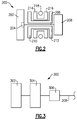
- Figure 2 shows an embodiment 200, wherein there is a fan drive turbine 208 driving a shaft 206 to in turn drive a fan rotor 202.
- a gear reduction 204 may be positioned between the fan drive turbine 208 and the fan rotor 202.
- This gear reduction 204 may be structured and operate like the gear reduction disclosed above.
- a first compressor rotor 210 is driven by an intermediate pressure turbine 212, and a second stage compressor rotor 214 is driven by a high pressure turbine rotor 216.
- a combustion section 218 is positioned intermediate the second compressor rotor 214 and the high pressure turbine section 216.
- Figure 3 shows yet another embodiment 300 wherein a fan rotor 302 and a first stage compressor 304 rotate at a common speed.
- the gear reduction 306 (which may be structured as disclosed above) is intermediate the compressor rotor 304 and a shaft 308 which is driven by a low pressure turbine section, i.e., a fan drive turbine section.
- the compressor immediately upstream and the turbine immediately downstream of the combustor section comprise a high speed spool. Rotating this spool at even higher speeds and pressures can increase the overall efficiency of the engine. Increased speeds and pressures typically result in higher temperatures, requiring thermal management techniques such as thermal barrier coatings and/or active cooling of the components.
- An active cooling system 100 is shown in Figure 4 , which coordinates the cooling between the high pressure compressor 52 and the high pressure turbine 54 to lower the temperatures of the high speed spool thus permitting higher speeds and overall pressure ratio (OPR).
- the high pressure compressor 52 includes a compressor rotor assembly 60 that includes a stack of rotating stages 62A-62D provided by rotor disks 64A-64D, as shown in Figures 4 and 6 .
- the compressor rotor assembly 60 has spaced apart inner and outer portions 70, 72 that provide an axially extending cooling channel 84.
- the outer portion 72 has a blade inner surface 73.
- the inner portion 70 provides a rotor outer peripheral surface 71.
- the cooling channel 84 is defined between the rotor outer peripheral surface 71 and the blade inner surface 73.
- Compressor blades 78 extend radially outward from the outer portion 72, which provides an inner core flow path for the core gas flow C.
- An inlet opening 88 is configured to receive a first cooling flow 76 fluidly connecting the outer portion 72 to the cooling channel 84.
- the compressor rotor assembly 60 has one or more coolant exits 90, 92 in fluid communication with the cooling channel 84.
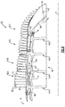
- Figure 6 illustrates an isolated schematic perspective view of the compressor rotor assembly 60 of the gas turbine engine 20.
- the rotor disks 64A-64D are bonded to one another using TLP or P/TLP to create the integral cooling channels 84.
- the blades 78 are bonded to the inner portion 70, forming "rotor spokes," such that the blades' platforms provide the outer portion 72.
- the blades 78 may also be integrally formed with the inner portion 70 as a unitary, one-piece component without separately bonded pieces. Of course other arrangements can be used to provide the cooling channels 84.
- the coolant exits 90, 92 are provided in a hub 96 at the end of the stack.
- the first cooling fluid 76 may be routed through the outer shaft 50, or in any other suitable manner, to communicate the first cooling fluid 76 over to the turbine rotor 132.
- FIG. 7 schematically illustrates an example high pressure turbine section 54 in more detail.
- the portions of the rotors extending radially inward do not extend into a single thermally isolated cooling plenum, but rather extend into a plenum with multiple environments.
- the thermally isolated cooling plenum 180 is in a space positioned radially inward of the core gas flow path C, radially inward of the high pressure turbine section 54.
- the high pressure turbine 54 includes a turbine rotor 132, as shown in Figures 4 and 7 .
- the compressor rotor assembly 60 is configured to communicate the first cooling flow 76 to the turbine rotor 132.
- a bleed source 91 is configured to provide a second cooling flow 190.
- the combustor section 56 includes a tangential onboard injector 120 in fluid communication with the bleed source 91.
- the second cooling flow 190 is passed through an exit guide vane 93 to the tangential onboard injector 120, which is configured to communicate the second cooling flow 190 to the turbine rotor 132.
- the air within the plenum 180 is thermally isolated from adjacent air by a forward wall 150, an aft wall 160, an inner diameter of the core flow path C, and the outer shaft 50.
- Each of the forward wall 150 and the aft wall 160 extends radially inward from the inner diameter of the core flow path C, and is sealed against the turbine rotor 132.
- the forward wall 150 is sealed against a root portion 134 of the forward rotor 130 via a seal 152 (alternately referred to as a fore seal).
- the aft wall 160 is sealed against the turbine rotor 132 via a seal 162 (alternately referred to as an aft seal).
- the seals 152, 162 provide a barrier that prevents air from entering the thermally isolated cooling plenum 180 from the adjacent cavities that are at a higher pressure.
- the thermally isolated cooling plenum 180 receives the second cooling flow 190 from the tangential onboard injector 120, which extends through the forward wall 150. Due to the sealed nature of the thermally isolated cooling plenum 180, the only source of air entering the thermally isolated cooling plenum 180 is the first and second cooling flows 76, 190.
- the first cooling flow 76 enters the plenum 180 through the outer shaft 50 and/or the tangential onboard injector 120. In order to minimize thermal gradients the first and second cooling fluids 76, 190 cool the entire turbine rotor 132.
- the active cooling system 100 coordinates cooling flows in the high pressure compressor 52 and the high pressure turbine 54 to lower temperatures, which enables spool speeds and pressures to be increased and engine efficiency improved.
- a method 350 of cooling the high spool includes providing a first cooling flow 76 through an inlet opening 88 in an inner core flow path of a compressor rotor assembly 60, as indicated at block 352 of Figure 5 .
- a second cooling flow 190 is provided to the tangential onboard injector 120, as indicated at block 356.
- the first and second cooling flows 76, 190 are passed to the turbine rotor 132 to cool the turbine rotor 132, as indicated at blocks 354, 358, 360.
Landscapes
- Engineering & Computer Science (AREA)
- Mechanical Engineering (AREA)
- General Engineering & Computer Science (AREA)
- Chemical & Material Sciences (AREA)
- Combustion & Propulsion (AREA)
- Physics & Mathematics (AREA)
- Fluid Mechanics (AREA)
- Turbine Rotor Nozzle Sealing (AREA)
Applications Claiming Priority (1)
| Application Number | Priority Date | Filing Date | Title |
|---|---|---|---|
| US14/597,442 US9677475B2 (en) | 2015-01-15 | 2015-01-15 | Gas turbine engine with high speed and temperature spool cooling system |
Publications (2)
| Publication Number | Publication Date |
|---|---|
| EP3045681A1 true EP3045681A1 (fr) | 2016-07-20 |
| EP3045681B1 EP3045681B1 (fr) | 2018-10-03 |
Family
ID=55129769
Family Applications (1)
| Application Number | Title | Priority Date | Filing Date |
|---|---|---|---|
| EP16151310.6A Active EP3045681B1 (fr) | 2015-01-15 | 2016-01-14 | Moteur à turbine à gaz avec corps haute température et système de refroidissement associé |
Country Status (2)
| Country | Link |
|---|---|
| US (1) | US9677475B2 (fr) |
| EP (1) | EP3045681B1 (fr) |
Cited By (1)
| Publication number | Priority date | Publication date | Assignee | Title |
|---|---|---|---|---|
| EP3318859A1 (fr) * | 2016-11-08 | 2018-05-09 | United Technologies Corporation | Sécurité d'air de refroidissement refroidi par l'intermédiaire d'une unité interchangeable de ligne de surveillance de température |
Families Citing this family (4)
| Publication number | Priority date | Publication date | Assignee | Title |
|---|---|---|---|---|
| US10883387B2 (en) * | 2016-03-07 | 2021-01-05 | General Electric Company | Gas turbine exhaust diffuser with air injection |
| US10954796B2 (en) * | 2018-08-13 | 2021-03-23 | Raytheon Technologies Corporation | Rotor bore conditioning for a gas turbine engine |
| US11834196B2 (en) * | 2019-10-15 | 2023-12-05 | General Electric Company | System and method for control for unducted engine |
| CN117905537B (zh) * | 2024-02-06 | 2025-05-06 | 中国航发湖南动力机械研究所 | 一种引射冷却结构及发动机 |
Citations (4)
| Publication number | Priority date | Publication date | Assignee | Title |
|---|---|---|---|---|
| EP1533473A1 (fr) * | 2003-11-20 | 2005-05-25 | General Electric Company | Triple circuit de refroidissement de turbine |
| US20120060507A1 (en) * | 2010-09-10 | 2012-03-15 | Rolls-Royce Plc | Gas turbine engine |
| US20130108413A1 (en) * | 2011-10-28 | 2013-05-02 | Gabriel L. Suciu | Secondary flow arrangement for slotted rotor |
| WO2014159200A1 (fr) * | 2013-03-14 | 2014-10-02 | United Technologies Corporation | Pressurisation d'une roue de turbine d'un moteur à turbine à gaz |
Family Cites Families (8)
| Publication number | Priority date | Publication date | Assignee | Title |
|---|---|---|---|---|
| GB2108202B (en) * | 1980-10-10 | 1984-05-10 | Rolls Royce | Air cooling systems for gas turbine engines |
| US5555721A (en) * | 1994-09-28 | 1996-09-17 | General Electric Company | Gas turbine engine cooling supply circuit |
| FR2782539B1 (fr) * | 1998-08-20 | 2000-10-06 | Snecma | Turbomachine comportant un dispositif de fourniture de gaz pressurise |
| US6234746B1 (en) * | 1999-08-04 | 2001-05-22 | General Electric Co. | Apparatus and methods for cooling rotary components in a turbine |
| JP4091874B2 (ja) * | 2003-05-21 | 2008-05-28 | 本田技研工業株式会社 | ガスタービンエンジンの二次エア供給装置 |
| US7743613B2 (en) * | 2006-11-10 | 2010-06-29 | General Electric Company | Compound turbine cooled engine |
| US9938831B2 (en) | 2011-10-28 | 2018-04-10 | United Technologies Corporation | Spoked rotor for a gas turbine engine |
| US8784062B2 (en) | 2011-10-28 | 2014-07-22 | United Technologies Corporation | Asymmetrically slotted rotor for a gas turbine engine |
-
2015
- 2015-01-15 US US14/597,442 patent/US9677475B2/en active Active
-
2016
- 2016-01-14 EP EP16151310.6A patent/EP3045681B1/fr active Active
Patent Citations (4)
| Publication number | Priority date | Publication date | Assignee | Title |
|---|---|---|---|---|
| EP1533473A1 (fr) * | 2003-11-20 | 2005-05-25 | General Electric Company | Triple circuit de refroidissement de turbine |
| US20120060507A1 (en) * | 2010-09-10 | 2012-03-15 | Rolls-Royce Plc | Gas turbine engine |
| US20130108413A1 (en) * | 2011-10-28 | 2013-05-02 | Gabriel L. Suciu | Secondary flow arrangement for slotted rotor |
| WO2014159200A1 (fr) * | 2013-03-14 | 2014-10-02 | United Technologies Corporation | Pressurisation d'une roue de turbine d'un moteur à turbine à gaz |
Cited By (1)
| Publication number | Priority date | Publication date | Assignee | Title |
|---|---|---|---|---|
| EP3318859A1 (fr) * | 2016-11-08 | 2018-05-09 | United Technologies Corporation | Sécurité d'air de refroidissement refroidi par l'intermédiaire d'une unité interchangeable de ligne de surveillance de température |
Also Published As
| Publication number | Publication date |
|---|---|
| US20160208713A1 (en) | 2016-07-21 |
| US9677475B2 (en) | 2017-06-13 |
| EP3045681B1 (fr) | 2018-10-03 |
Similar Documents
| Publication | Publication Date | Title |
|---|---|---|
| US11092025B2 (en) | Gas turbine engine with dove-tailed TOBI vane | |
| EP2971673B1 (fr) | Pressurisation d'une roue de turbine d'un moteur à turbine à gaz | |
| EP3009599A1 (fr) | Component de turbine à gaz avec un refroidissement par film fluide. | |
| EP3179033B1 (fr) | Ensemble de refroidissement pour aube de turbine à gaz | |
| US10041358B2 (en) | Gas turbine engine blade squealer pockets | |
| EP3039264B1 (fr) | Agencement de refroidissement et de mélange de diffuseur de turbine à gaz | |
| EP3045681B1 (fr) | Moteur à turbine à gaz avec corps haute température et système de refroidissement associé | |
| EP2971585B1 (fr) | Joint d'étanchéité de rail d'aube de turbine à gaz | |
| EP2867501B1 (fr) | Plateforme d'aube de turbine comprenant des trous de refroidissement de canal en u | |
| US10364679B2 (en) | Gas turbine engine compressor rotor vaporization cooling | |
| EP3461993A1 (fr) | Surface portante de moteur à turbine à gaz | |
| US20160003163A1 (en) | Gas turbine engine with short transition duct | |
| US10794207B2 (en) | Gas turbine engine airfoil component platform seal cooling | |
| EP3059391A1 (fr) | Refroidissement de pale de turbine à gaz à l'aide d'une aube de stator amont | |
| EP3450697B1 (fr) | Segment d'aubes de guidage et moteur à turbine à gaz associé | |
| EP3392472B1 (fr) | Section de compresseur pour un moteur à turbine à gaz, moteur à turbine à gaz et procédé de fonctionnement d'une section de compresseur dans un moteur à turbine à gaz, associés | |
| EP3045658B1 (fr) | Rotor de moteur de turbine à gaz | |
| EP3179034B1 (fr) | Air de refroidissement à plusieurs sources pour une turbine |
Legal Events
| Date | Code | Title | Description |
|---|---|---|---|
| PUAI | Public reference made under article 153(3) epc to a published international application that has entered the european phase |
Free format text: ORIGINAL CODE: 0009012 |
|
| AK | Designated contracting states |
Kind code of ref document: A1 Designated state(s): AL AT BE BG CH CY CZ DE DK EE ES FI FR GB GR HR HU IE IS IT LI LT LU LV MC MK MT NL NO PL PT RO RS SE SI SK SM TR |
|
| AX | Request for extension of the european patent |
Extension state: BA ME |
|
| RAP1 | Party data changed (applicant data changed or rights of an application transferred) |
Owner name: UNITED TECHNOLOGIES CORPORATION |
|
| STAA | Information on the status of an ep patent application or granted ep patent |
Free format text: STATUS: REQUEST FOR EXAMINATION WAS MADE |
|
| 17P | Request for examination filed |
Effective date: 20170120 |
|
| RBV | Designated contracting states (corrected) |
Designated state(s): AL AT BE BG CH CY CZ DE DK EE ES FI FR GB GR HR HU IE IS IT LI LT LU LV MC MK MT NL NO PL PT RO RS SE SI SK SM TR |
|
| GRAP | Despatch of communication of intention to grant a patent |
Free format text: ORIGINAL CODE: EPIDOSNIGR1 |
|
| STAA | Information on the status of an ep patent application or granted ep patent |
Free format text: STATUS: GRANT OF PATENT IS INTENDED |
|
| INTG | Intention to grant announced |
Effective date: 20180507 |
|
| GRAS | Grant fee paid |
Free format text: ORIGINAL CODE: EPIDOSNIGR3 |
|
| GRAA | (expected) grant |
Free format text: ORIGINAL CODE: 0009210 |
|
| STAA | Information on the status of an ep patent application or granted ep patent |
Free format text: STATUS: THE PATENT HAS BEEN GRANTED |
|
| AK | Designated contracting states |
Kind code of ref document: B1 Designated state(s): AL AT BE BG CH CY CZ DE DK EE ES FI FR GB GR HR HU IE IS IT LI LT LU LV MC MK MT NL NO PL PT RO RS SE SI SK SM TR |
|
| REG | Reference to a national code |
Ref country code: GB Ref legal event code: FG4D |
|
| REG | Reference to a national code |
Ref country code: CH Ref legal event code: EP Ref country code: AT Ref legal event code: REF Ref document number: 1048826 Country of ref document: AT Kind code of ref document: T Effective date: 20181015 |
|
| REG | Reference to a national code |
Ref country code: IE Ref legal event code: FG4D Ref country code: DE Ref legal event code: R096 Ref document number: 602016006111 Country of ref document: DE |
|
| REG | Reference to a national code |
Ref country code: NL Ref legal event code: MP Effective date: 20181003 |
|
| REG | Reference to a national code |
Ref country code: LT Ref legal event code: MG4D |
|
| REG | Reference to a national code |
Ref country code: AT Ref legal event code: MK05 Ref document number: 1048826 Country of ref document: AT Kind code of ref document: T Effective date: 20181003 |
|
| PG25 | Lapsed in a contracting state [announced via postgrant information from national office to epo] |
Ref country code: NL Free format text: LAPSE BECAUSE OF FAILURE TO SUBMIT A TRANSLATION OF THE DESCRIPTION OR TO PAY THE FEE WITHIN THE PRESCRIBED TIME-LIMIT Effective date: 20181003 |
|
| PG25 | Lapsed in a contracting state [announced via postgrant information from national office to epo] |
Ref country code: LV Free format text: LAPSE BECAUSE OF FAILURE TO SUBMIT A TRANSLATION OF THE DESCRIPTION OR TO PAY THE FEE WITHIN THE PRESCRIBED TIME-LIMIT Effective date: 20181003 Ref country code: AT Free format text: LAPSE BECAUSE OF FAILURE TO SUBMIT A TRANSLATION OF THE DESCRIPTION OR TO PAY THE FEE WITHIN THE PRESCRIBED TIME-LIMIT Effective date: 20181003 Ref country code: FI Free format text: LAPSE BECAUSE OF FAILURE TO SUBMIT A TRANSLATION OF THE DESCRIPTION OR TO PAY THE FEE WITHIN THE PRESCRIBED TIME-LIMIT Effective date: 20181003 Ref country code: BG Free format text: LAPSE BECAUSE OF FAILURE TO SUBMIT A TRANSLATION OF THE DESCRIPTION OR TO PAY THE FEE WITHIN THE PRESCRIBED TIME-LIMIT Effective date: 20190103 Ref country code: IS Free format text: LAPSE BECAUSE OF FAILURE TO SUBMIT A TRANSLATION OF THE DESCRIPTION OR TO PAY THE FEE WITHIN THE PRESCRIBED TIME-LIMIT Effective date: 20190203 Ref country code: NO Free format text: LAPSE BECAUSE OF FAILURE TO SUBMIT A TRANSLATION OF THE DESCRIPTION OR TO PAY THE FEE WITHIN THE PRESCRIBED TIME-LIMIT Effective date: 20190103 Ref country code: CZ Free format text: LAPSE BECAUSE OF FAILURE TO SUBMIT A TRANSLATION OF THE DESCRIPTION OR TO PAY THE FEE WITHIN THE PRESCRIBED TIME-LIMIT Effective date: 20181003 Ref country code: HR Free format text: LAPSE BECAUSE OF FAILURE TO SUBMIT A TRANSLATION OF THE DESCRIPTION OR TO PAY THE FEE WITHIN THE PRESCRIBED TIME-LIMIT Effective date: 20181003 Ref country code: PL Free format text: LAPSE BECAUSE OF FAILURE TO SUBMIT A TRANSLATION OF THE DESCRIPTION OR TO PAY THE FEE WITHIN THE PRESCRIBED TIME-LIMIT Effective date: 20181003 Ref country code: LT Free format text: LAPSE BECAUSE OF FAILURE TO SUBMIT A TRANSLATION OF THE DESCRIPTION OR TO PAY THE FEE WITHIN THE PRESCRIBED TIME-LIMIT Effective date: 20181003 Ref country code: ES Free format text: LAPSE BECAUSE OF FAILURE TO SUBMIT A TRANSLATION OF THE DESCRIPTION OR TO PAY THE FEE WITHIN THE PRESCRIBED TIME-LIMIT Effective date: 20181003 |
|
| PG25 | Lapsed in a contracting state [announced via postgrant information from national office to epo] |
Ref country code: SE Free format text: LAPSE BECAUSE OF FAILURE TO SUBMIT A TRANSLATION OF THE DESCRIPTION OR TO PAY THE FEE WITHIN THE PRESCRIBED TIME-LIMIT Effective date: 20181003 Ref country code: GR Free format text: LAPSE BECAUSE OF FAILURE TO SUBMIT A TRANSLATION OF THE DESCRIPTION OR TO PAY THE FEE WITHIN THE PRESCRIBED TIME-LIMIT Effective date: 20190104 Ref country code: PT Free format text: LAPSE BECAUSE OF FAILURE TO SUBMIT A TRANSLATION OF THE DESCRIPTION OR TO PAY THE FEE WITHIN THE PRESCRIBED TIME-LIMIT Effective date: 20190203 Ref country code: AL Free format text: LAPSE BECAUSE OF FAILURE TO SUBMIT A TRANSLATION OF THE DESCRIPTION OR TO PAY THE FEE WITHIN THE PRESCRIBED TIME-LIMIT Effective date: 20181003 Ref country code: RS Free format text: LAPSE BECAUSE OF FAILURE TO SUBMIT A TRANSLATION OF THE DESCRIPTION OR TO PAY THE FEE WITHIN THE PRESCRIBED TIME-LIMIT Effective date: 20181003 |
|
| REG | Reference to a national code |
Ref country code: DE Ref legal event code: R097 Ref document number: 602016006111 Country of ref document: DE |
|
| PG25 | Lapsed in a contracting state [announced via postgrant information from national office to epo] |
Ref country code: DK Free format text: LAPSE BECAUSE OF FAILURE TO SUBMIT A TRANSLATION OF THE DESCRIPTION OR TO PAY THE FEE WITHIN THE PRESCRIBED TIME-LIMIT Effective date: 20181003 Ref country code: IT Free format text: LAPSE BECAUSE OF FAILURE TO SUBMIT A TRANSLATION OF THE DESCRIPTION OR TO PAY THE FEE WITHIN THE PRESCRIBED TIME-LIMIT Effective date: 20181003 |
|
| PLBE | No opposition filed within time limit |
Free format text: ORIGINAL CODE: 0009261 |
|
| STAA | Information on the status of an ep patent application or granted ep patent |
Free format text: STATUS: NO OPPOSITION FILED WITHIN TIME LIMIT |
|
| PG25 | Lapsed in a contracting state [announced via postgrant information from national office to epo] |
Ref country code: SK Free format text: LAPSE BECAUSE OF FAILURE TO SUBMIT A TRANSLATION OF THE DESCRIPTION OR TO PAY THE FEE WITHIN THE PRESCRIBED TIME-LIMIT Effective date: 20181003 Ref country code: RO Free format text: LAPSE BECAUSE OF FAILURE TO SUBMIT A TRANSLATION OF THE DESCRIPTION OR TO PAY THE FEE WITHIN THE PRESCRIBED TIME-LIMIT Effective date: 20181003 Ref country code: EE Free format text: LAPSE BECAUSE OF FAILURE TO SUBMIT A TRANSLATION OF THE DESCRIPTION OR TO PAY THE FEE WITHIN THE PRESCRIBED TIME-LIMIT Effective date: 20181003 Ref country code: SM Free format text: LAPSE BECAUSE OF FAILURE TO SUBMIT A TRANSLATION OF THE DESCRIPTION OR TO PAY THE FEE WITHIN THE PRESCRIBED TIME-LIMIT Effective date: 20181003 Ref country code: MC Free format text: LAPSE BECAUSE OF FAILURE TO SUBMIT A TRANSLATION OF THE DESCRIPTION OR TO PAY THE FEE WITHIN THE PRESCRIBED TIME-LIMIT Effective date: 20181003 |
|
| REG | Reference to a national code |
Ref country code: CH Ref legal event code: PL |
|
| 26N | No opposition filed |
Effective date: 20190704 |
|
| PG25 | Lapsed in a contracting state [announced via postgrant information from national office to epo] |
Ref country code: LU Free format text: LAPSE BECAUSE OF NON-PAYMENT OF DUE FEES Effective date: 20190114 |
|
| REG | Reference to a national code |
Ref country code: BE Ref legal event code: MM Effective date: 20190131 |
|
| REG | Reference to a national code |
Ref country code: IE Ref legal event code: MM4A |
|
| PG25 | Lapsed in a contracting state [announced via postgrant information from national office to epo] |
Ref country code: SI Free format text: LAPSE BECAUSE OF FAILURE TO SUBMIT A TRANSLATION OF THE DESCRIPTION OR TO PAY THE FEE WITHIN THE PRESCRIBED TIME-LIMIT Effective date: 20181003 |
|
| PG25 | Lapsed in a contracting state [announced via postgrant information from national office to epo] |
Ref country code: BE Free format text: LAPSE BECAUSE OF NON-PAYMENT OF DUE FEES Effective date: 20190131 |
|
| PG25 | Lapsed in a contracting state [announced via postgrant information from national office to epo] |
Ref country code: CH Free format text: LAPSE BECAUSE OF NON-PAYMENT OF DUE FEES Effective date: 20190131 Ref country code: LI Free format text: LAPSE BECAUSE OF NON-PAYMENT OF DUE FEES Effective date: 20190131 |
|
| PG25 | Lapsed in a contracting state [announced via postgrant information from national office to epo] |
Ref country code: IE Free format text: LAPSE BECAUSE OF NON-PAYMENT OF DUE FEES Effective date: 20190114 |
|
| PG25 | Lapsed in a contracting state [announced via postgrant information from national office to epo] |
Ref country code: TR Free format text: LAPSE BECAUSE OF FAILURE TO SUBMIT A TRANSLATION OF THE DESCRIPTION OR TO PAY THE FEE WITHIN THE PRESCRIBED TIME-LIMIT Effective date: 20181003 |
|
| PG25 | Lapsed in a contracting state [announced via postgrant information from national office to epo] |
Ref country code: MT Free format text: LAPSE BECAUSE OF NON-PAYMENT OF DUE FEES Effective date: 20190114 |
|
| PG25 | Lapsed in a contracting state [announced via postgrant information from national office to epo] |
Ref country code: CY Free format text: LAPSE BECAUSE OF FAILURE TO SUBMIT A TRANSLATION OF THE DESCRIPTION OR TO PAY THE FEE WITHIN THE PRESCRIBED TIME-LIMIT Effective date: 20181003 |
|
| PG25 | Lapsed in a contracting state [announced via postgrant information from national office to epo] |
Ref country code: HU Free format text: LAPSE BECAUSE OF FAILURE TO SUBMIT A TRANSLATION OF THE DESCRIPTION OR TO PAY THE FEE WITHIN THE PRESCRIBED TIME-LIMIT; INVALID AB INITIO Effective date: 20160114 |
|
| PG25 | Lapsed in a contracting state [announced via postgrant information from national office to epo] |
Ref country code: MK Free format text: LAPSE BECAUSE OF FAILURE TO SUBMIT A TRANSLATION OF THE DESCRIPTION OR TO PAY THE FEE WITHIN THE PRESCRIBED TIME-LIMIT Effective date: 20181003 |
|
| REG | Reference to a national code |
Ref country code: DE Ref legal event code: R081 Ref document number: 602016006111 Country of ref document: DE Owner name: RAYTHEON TECHNOLOGIES CORPORATION (N.D.GES.D.S, US Free format text: FORMER OWNER: UNITED TECHNOLOGIES CORPORATION, FARMINGTON, CONN., US Ref country code: DE Ref legal event code: R081 Ref document number: 602016006111 Country of ref document: DE Owner name: RTX CORPORATION (N.D.GES.D. STAATES DELAWARE),, US Free format text: FORMER OWNER: UNITED TECHNOLOGIES CORPORATION, FARMINGTON, CONN., US |
|
| P01 | Opt-out of the competence of the unified patent court (upc) registered |
Effective date: 20230520 |
|
| REG | Reference to a national code |
Ref country code: DE Ref legal event code: R081 Ref document number: 602016006111 Country of ref document: DE Owner name: RTX CORPORATION (N.D.GES.D. STAATES DELAWARE),, US Free format text: FORMER OWNER: RAYTHEON TECHNOLOGIES CORPORATION (N.D.GES.D.STAATES DELAWARE), ARLINGTON, VA, US |
|
| PGFP | Annual fee paid to national office [announced via postgrant information from national office to epo] |
Ref country code: GB Payment date: 20251220 Year of fee payment: 11 |
|
| PGFP | Annual fee paid to national office [announced via postgrant information from national office to epo] |
Ref country code: FR Payment date: 20251217 Year of fee payment: 11 |
|
| PGFP | Annual fee paid to national office [announced via postgrant information from national office to epo] |
Ref country code: DE Payment date: 20251217 Year of fee payment: 11 |