EP3045685A1 - Fixation mécanique et agencement associé de fixation d'aube de redresseur - Google Patents
Fixation mécanique et agencement associé de fixation d'aube de redresseur Download PDFInfo
- Publication number
- EP3045685A1 EP3045685A1 EP15190242.6A EP15190242A EP3045685A1 EP 3045685 A1 EP3045685 A1 EP 3045685A1 EP 15190242 A EP15190242 A EP 15190242A EP 3045685 A1 EP3045685 A1 EP 3045685A1
- Authority
- EP
- European Patent Office
- Prior art keywords
- leg
- airfoil
- joint member
- temperature
- sidewall
- Prior art date
- Legal status (The legal status is an assumption and is not a legal conclusion. Google has not performed a legal analysis and makes no representation as to the accuracy of the status listed.)
- Granted
Links
Images


Classifications
-
- F—MECHANICAL ENGINEERING; LIGHTING; HEATING; WEAPONS; BLASTING
- F01—MACHINES OR ENGINES IN GENERAL; ENGINE PLANTS IN GENERAL; STEAM ENGINES
- F01D—NON-POSITIVE DISPLACEMENT MACHINES OR ENGINES, e.g. STEAM TURBINES
- F01D25/00—Component parts, details, or accessories, not provided for in, or of interest apart from, other groups
- F01D25/24—Casings; Casing parts, e.g. diaphragms, casing fastenings
- F01D25/246—Fastening of diaphragms or stator-rings
-
- F—MECHANICAL ENGINEERING; LIGHTING; HEATING; WEAPONS; BLASTING
- F01—MACHINES OR ENGINES IN GENERAL; ENGINE PLANTS IN GENERAL; STEAM ENGINES
- F01D—NON-POSITIVE DISPLACEMENT MACHINES OR ENGINES, e.g. STEAM TURBINES
- F01D25/00—Component parts, details, or accessories, not provided for in, or of interest apart from, other groups
- F01D25/005—Selecting particular materials
-
- F—MECHANICAL ENGINEERING; LIGHTING; HEATING; WEAPONS; BLASTING
- F01—MACHINES OR ENGINES IN GENERAL; ENGINE PLANTS IN GENERAL; STEAM ENGINES
- F01D—NON-POSITIVE DISPLACEMENT MACHINES OR ENGINES, e.g. STEAM TURBINES
- F01D9/00—Stators
- F01D9/02—Nozzles; Nozzle boxes; Stator blades; Guide conduits, e.g. individual nozzles
-
- F—MECHANICAL ENGINEERING; LIGHTING; HEATING; WEAPONS; BLASTING
- F05—INDEXING SCHEMES RELATING TO ENGINES OR PUMPS IN VARIOUS SUBCLASSES OF CLASSES F01-F04
- F05D—INDEXING SCHEME FOR ASPECTS RELATING TO NON-POSITIVE-DISPLACEMENT MACHINES OR ENGINES, GAS-TURBINES OR JET-PROPULSION PLANTS
- F05D2230/00—Manufacture
- F05D2230/60—Assembly methods
- F05D2230/64—Assembly methods using positioning or alignment devices for aligning or centring, e.g. pins
- F05D2230/642—Assembly methods using positioning or alignment devices for aligning or centring, e.g. pins using maintaining alignment while permitting differential dilatation
-
- F—MECHANICAL ENGINEERING; LIGHTING; HEATING; WEAPONS; BLASTING
- F05—INDEXING SCHEMES RELATING TO ENGINES OR PUMPS IN VARIOUS SUBCLASSES OF CLASSES F01-F04
- F05D—INDEXING SCHEME FOR ASPECTS RELATING TO NON-POSITIVE-DISPLACEMENT MACHINES OR ENGINES, GAS-TURBINES OR JET-PROPULSION PLANTS
- F05D2300/00—Materials; Properties thereof
- F05D2300/50—Intrinsic material properties or characteristics
- F05D2300/502—Thermal properties
- F05D2300/5021—Expansivity
- F05D2300/50212—Expansivity dissimilar
-
- F—MECHANICAL ENGINEERING; LIGHTING; HEATING; WEAPONS; BLASTING
- F05—INDEXING SCHEMES RELATING TO ENGINES OR PUMPS IN VARIOUS SUBCLASSES OF CLASSES F01-F04
- F05D—INDEXING SCHEME FOR ASPECTS RELATING TO NON-POSITIVE-DISPLACEMENT MACHINES OR ENGINES, GAS-TURBINES OR JET-PROPULSION PLANTS
- F05D2300/00—Materials; Properties thereof
- F05D2300/60—Properties or characteristics given to material by treatment or manufacturing
- F05D2300/603—Composites; e.g. fibre-reinforced
- F05D2300/6033—Ceramic matrix composites [CMC]
-
- Y—GENERAL TAGGING OF NEW TECHNOLOGICAL DEVELOPMENTS; GENERAL TAGGING OF CROSS-SECTIONAL TECHNOLOGIES SPANNING OVER SEVERAL SECTIONS OF THE IPC; TECHNICAL SUBJECTS COVERED BY FORMER USPC CROSS-REFERENCE ART COLLECTIONS [XRACs] AND DIGESTS
- Y02—TECHNOLOGIES OR APPLICATIONS FOR MITIGATION OR ADAPTATION AGAINST CLIMATE CHANGE
- Y02T—CLIMATE CHANGE MITIGATION TECHNOLOGIES RELATED TO TRANSPORTATION
- Y02T50/00—Aeronautics or air transport
- Y02T50/60—Efficient propulsion technologies, e.g. for aircraft
Definitions
- This description relates to component connection assemblies, and, more particularly, to a component connection assembly that includes materials having different coefficients of thermal expansion (CTE).
- CTE coefficients of thermal expansion
- CMC ceramic matrix composite material
- a mechanical connecting joint in one aspect, includes a first joint member formed of a material having a first coefficient of thermal expansion (CTE) value, the first joint member comprising a first sidewall, a second opposite sidewall, and a body extending therebetween.
- the mechanical connecting joint further includes a second joint member formed of a material having a second CTE value, the second CTE being less than the first CTE.
- the second joint member includes a first leg facing the first sidewall, a second leg facing the second sidewall, and a connecting member extending between the first leg and the second leg. A first gap is formed between the first joint member and the first leg and a second gap is formed between the first joint member and the second leg.
- a vane attachment assembly in another aspect, includes a plurality of airfoil vane shanks extending from a vane platform, each of the airfoil shanks comprising a ceramic matrix composite material (CMC) having a first coefficient of thermal expansion (CTE).
- the airfoil attachment assembly also includes a vane hanger formed of a metal material having a second CTE, the airfoil hanger positioned between adjacent ones of the plurality of airfoil vane shanks, a surface of the airfoil hanger configured to expand outwardly towards the adjacent ones of the plurality of airfoil vane shanks thereby exerting a force into the adjacent ones of the plurality of airfoil vane shanks.
- a gas turbine engine assembly in yet another aspect, includes a rotatable member comprising an axis of rotation and supported within a casing by a plurality of bearings.
- the gas turbine engine assembly also includes a vane hanger comprising a metal material having a first coefficient of thermal expansion (CTE) positioned radially outward from the rotatable member within the casing, the airfoil hanger comprising a radially outer portion fixedly coupled to the casing and a radially inner portion comprising a vane attachment.
- CTE coefficient of thermal expansion
- the gas turbine engine assembly further includes a vane comprising a radially outer shank portion comprising a first leg and a second leg, each of the first and second legs extending radially outwardly on opposite sides of the airfoil attachment, each of the first and second legs comprising a ceramic matrix composite (CMC) material having a second CTE.
- CMC ceramic matrix composite
- Embodiments of the present disclosure describe an attachment configuration for joining two components, for example, a Ceramic Matrix Composite (CMC) vane to a metal airfoil hanger.
- CMC Ceramic Matrix Composite
- the attachment configuration should be understood to be applicable for any CMC to metal component joint applied to other CMC vanes and structures.
- a metallic hanger is fitted between and pinned to the two CMC vane mounting shanks that extend from the airfoils as continuous plies through the outer end wall.
- the metallic pins and hanger are fitted with the CMC such that the desired clamping load is achieved as the metal out grows the CMC at operating temperature.
- the same attachment configuration can be used to mount the metallic inner mid-seal box between vane shanks extending through the inner flow path end wall.
- Metallic components being attached to the CMC vane are configured so that they are constrained between or inside the CMC. It therefore uses the difference in coefficient of thermal expansion (CTE) between the CMC and metal to increase the clamping load between the parts at elevated operating temperatures rather than decrease it.
- CTE coefficient of thermal expansion
- a metallic hanger is fitted between and pinned to the two CMC vane mounting shanks. The metallic hanger is fitted between the CMC vane shanks such that the desired clamping load is achieved as the metal out grows the CMC at operating temperature.
- the metallic pin (or shoulder bolt) to CMC hole is sized so that the desired fit is achieved at operating temperature.
- FIG. 1 is a cross-sectional schematic illustration of an exemplary gas turbine engine assembly 10 having a longitudinal axis 11.
- Gas turbine engine assembly 10 includes a fan assembly 12 and a core gas turbine engine 13.
- Core gas turbine engine 13 includes a high pressure compressor 14, a combustor 16, and a high pressure turbine 18.
- gas turbine engine assembly 10 also includes a low pressure turbine 20, and a multi-stage booster compressor 22, and a splitter 44 that substantially circumscribes booster 22.
- Fan assembly 12 includes an array of fan blades 24 extending radially outward from a rotor disk 26.
- Gas turbine engine assembly 10 has an intake side 28 and an exhaust side 30.
- Fan assembly 12, booster 22, and turbine 20 are coupled together by a first rotor shaft 31, and compressor 14 and turbine 18 are coupled together by a second rotor shaft 32.
- engine assembly 10 may be, but is not limited to being, a LEAP or Passport 20 gas turbine engine available from General Electric Company, Cincinnati, Ohio.
- the compressed air that is discharged from booster 22 is channeled through compressor 14 wherein the airflow is further compressed and delivered to combustor 16.
- Hot products of combustion (not shown in FIG. 1 ) from combustor 16 are utilized to drive turbines 18 and 20, and turbine 20 is utilized to drive fan assembly 12 and booster 22 by way of shaft 31.
- Gas turbine engine assembly 10 is operable at a range of operating conditions between design operating conditions and off-design operating conditions.
- a second portion 52 of the airflow discharged from fan assembly 12 is channeled through a bypass duct 40 to bypass a portion of the airflow from fan assembly 12 around the core gas turbine engine 13. More specifically, bypass duct 40 extends between a fan casing 42 and splitter 44. Accordingly, a first portion 50 of the airflow from fan assembly 12 is channeled through booster 22 and then into compressor 14 as described above and a second portion 52 of the airflow from fan assembly 12 is channeled through bypass duct 40 to provide thrust for an aircraft, for example.
- Gas turbine engine assembly 10 also includes a fan frame assembly 60 to provide structural support for fan assembly 12 and is also utilized to couple fan assembly 12 to core gas turbine engine 13.
- Fan frame assembly 60 includes a plurality of outlet guide vanes 70 that typically extend substantially radially, between a radially-outer mounting flange and a radially-inner mounting flange, and are circumferentially-spaced within bypass duct 40.
- Guide vanes 70 serve to turn the airflow downstream from rotating blades such as fan blades 24.
- FIG. 2 is a cross-section of a portion of gas turbine engine assembly 10 (shown in FIG. 1 ) in accordance with an example embodiment of the present disclosure.
- a rotatable member 202 includes a plurality of radially outwardly extending blades 204. Blades 204 are interdigitated with stationary vanes 206 that extend radially inwardly from a casing 208 circumscribing rotatable member 202.
- Stationary vane 206 includes a platform 210, an airfoil 212 extending radially inwardly from platform 210, and a shank 214 extending radially outwardly from platform 210.
- Stationary vane 206 is coupled to casing 208 via a metal vane hanger 216.
- a slot 218 in CMC vane shank 214 allows for differential growth along a length 220 of shank 214.
- FIG. 3 is a radially inwardly looking view of a portion of gas turbine engine assembly 10 (shown in FIG. 1 ) in accordance with an example embodiment of the present disclosure.
- FIG. 4 is a radially inwardly looking view of the portion of gas turbine engine assembly 10 (shown in FIG. 1 ) in accordance with another embodiment of the present disclosure.
- vane 206 is formed of a ceramic matrix composite (CMC) material having a first coefficient of thermal expansion (CTE).
- CMC ceramic matrix composite
- CTE first coefficient of thermal expansion
- the only part of vane 206 that is visible in FIG. 3 is shank 214. Vane 206 exceeds into the page obscured by vane hanger 216.
- One or more locating or drift pins 302 extend from within shank 214 into vane hanger 216.
- Pins 302 may fit loosely into a respective bore 304 in each of shank 214 and may expand at operating temperature to a tight fit within bore 304 of shank 214.
- a gap 306 is formed between shank 214 and vane hanger 216. Gap 306 permits easy installation during an assembly process. When gas turbine engine assembly 10 (shown in FIG. 1 ) heats up during startup, gap 306 is reduced. In one embodiment gap 306 is reduced to approximately zero distance, meaning that a surface 308 of vane hanger 216 bears directly on a surface 310 of shank 214 and/or vane hanger 216.
- vane hanger 216 expands at a different rate than shank 214 because of a difference of CTE of the different materials of which shank 214 and vane hanger 216 are formed, vane hanger 216 expands to take up gap 306, touches shank 214 and applies a force against shank 214.
- the force is predetermined based on dimensions of shank 214 and vane hanger 216, their respective CTEs, and an expected operating temperature of gas turbine engine assembly 10 (shown in FIG. 1 ).
- three pins are used instead of four pins 302 as shown in FIG. 3 .
- a pair of pins 312 may share a through bore 314 that extends through shank 214 and vane hanger 216.
- FIG. 5 is a side elevation view of a mechanical connecting joint 400 in accordance with an example embodiment of the present disclosure.
- mechanical connecting joint 400 is configured to join a first joint member 402, such as, but, not limited to vane hanger 216 to a second joint member 403.
- First joint member 402 is formed of a material having a first coefficient of thermal expansion (CTE) value, for example, a metal or metallic material,
- First joint member 402 includes a first sidewall 404, a second opposite sidewall 406, and a body 408 extending therebetween.
- Second joint member 403, such as, but, not limited to shank 214, is formed of a ceramic matrix composite (CMC) material having a second CTE value, the second CTE being less than the first CTE.
- CMC ceramic matrix composite
- Second joint member 403 is formed of a includes a first leg 412 facing first sidewall 404, a second leg 414 facing second sidewall 406, and a connecting member 416 extending between first leg 412 and second leg 414.
- a first gap 418 is defined between first joint member 402 and first leg 412.
- a second gap 420 is defined between first joint member 402 and second leg 414.
- First gap 418 defines a first distance 422 between first joint member 402 and first leg 412 at a first temperature and a second distance 426 between first joint member 402 and first leg 412 at a second temperature, second distance 426 being different than first distance 422 and the second temperature being different than the first temperature.
- a change in distance between second distance 426 and first distance 422 is inversely related to a change in temperature between the second temperature and the first temperature.
- First joint member 402 exerts a first force 430 against first leg 402 at the first temperature and exerts a second force 432 against first leg 412 at the second temperature wherein second force 432 is greater than first force 430 and the second temperature is greater than the first temperature.
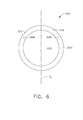
- FIG. 6 is a plan view of a mechanical connecting joint 500 in accordance with another example embodiment of the present disclosure.
- mechanical connecting joint 500 is configured to join a first joint member 502 to a second joint member 504.
- a first sidewall 506 and a second opposite sidewall 508 are arcuately shaped and together form a circular cross-section.
- a first leg 510 and a second leg 512 are arcuately shaped and together form a circular cross-section complementary to first sidewall 506 and second sidewall 508.
- mechanical connecting joint 500 is not circular, but rather may have other arcuate or square cross-sections, including, but not limited to, oval, oblong, elliptical, and the like.
- FIG. 7 is a perspective view of a cantilevered solid doublet CMC vane 700 including vane hanger 216, shank 214 and a metal mid seal 702.
- FIG. 8 is a perspective view cantilevered solid doublet CMC vane 700 showing only the CMC parts.
- an apparatus and system of joining components provide a cost-effective and reliable means for providing a rigid determinate attachment through relatively simple geometry and materials. More specifically, the apparatus and systems described herein facilitate the use of proven turbine attachment and assembly methods, which facilitates conventional sealing methods as well. As a result, the apparatus and systems described herein facilitate maintenance and assembly of components that operate in high temperature environments in a cost-effective and reliable manner.
Landscapes
- Engineering & Computer Science (AREA)
- Mechanical Engineering (AREA)
- General Engineering & Computer Science (AREA)
- Chemical & Material Sciences (AREA)
- Materials Engineering (AREA)
- Turbine Rotor Nozzle Sealing (AREA)
Applications Claiming Priority (1)
| Application Number | Priority Date | Filing Date | Title |
|---|---|---|---|
| US14/569,823 US20160169033A1 (en) | 2014-12-15 | 2014-12-15 | Apparatus and system for ceramic matrix composite attachment |
Publications (2)
| Publication Number | Publication Date |
|---|---|
| EP3045685A1 true EP3045685A1 (fr) | 2016-07-20 |
| EP3045685B1 EP3045685B1 (fr) | 2023-04-19 |
Family
ID=54364978
Family Applications (1)
| Application Number | Title | Priority Date | Filing Date |
|---|---|---|---|
| EP15190242.6A Active EP3045685B1 (fr) | 2014-12-15 | 2015-10-16 | Fixation mécanique et agencement associé de fixation d'aube de redresseur |
Country Status (6)
| Country | Link |
|---|---|
| US (1) | US20160169033A1 (fr) |
| EP (1) | EP3045685B1 (fr) |
| JP (1) | JP6725976B2 (fr) |
| CN (1) | CN105697149B (fr) |
| BR (1) | BR102015026072A2 (fr) |
| CA (1) | CA2907233C (fr) |
Families Citing this family (13)
| Publication number | Priority date | Publication date | Assignee | Title |
|---|---|---|---|---|
| GB201513232D0 (en) * | 2015-07-28 | 2015-09-09 | Rolls Royce Plc | A nozzle guide vane passage |
| FR3045716B1 (fr) * | 2015-12-18 | 2018-01-26 | Safran Aircraft Engines | Ensemble d'anneau de turbine avec maintien elastique a froid |
| US11802486B2 (en) * | 2017-11-13 | 2023-10-31 | General Electric Company | CMC component and fabrication using mechanical joints |
| FR3074518B1 (fr) * | 2017-12-05 | 2020-01-03 | Safran Aircraft Engines | Liaison entre un distributeur en composite a matrice ceramique et un support metallique d'une turbine de turbomachine |
| US10800128B2 (en) * | 2018-01-24 | 2020-10-13 | General Electric Company | Composite components having T or L-joints and methods for forming same |
| US11466580B2 (en) * | 2018-05-02 | 2022-10-11 | General Electric Company | CMC nozzle with interlocking mechanical joint and fabrication |
| US11008888B2 (en) | 2018-07-17 | 2021-05-18 | Rolls-Royce Corporation | Turbine vane assembly with ceramic matrix composite components |
| US10808553B2 (en) * | 2018-11-13 | 2020-10-20 | Rolls-Royce Plc | Inter-component seals for ceramic matrix composite turbine vane assemblies |
| US10895448B2 (en) * | 2019-04-09 | 2021-01-19 | General Electric Company | System and method for collecting measurement data of shaped cooling holes of CMC components |
| PL431184A1 (pl) * | 2019-09-17 | 2021-03-22 | General Electric Company Polska Spółka Z Ograniczoną Odpowiedzialnością | Zespół silnika turbinowego |
| US11255204B2 (en) * | 2019-11-05 | 2022-02-22 | Rolls-Royce Plc | Turbine vane assembly having ceramic matrix composite airfoils and metallic support spar |
| US10975709B1 (en) * | 2019-11-11 | 2021-04-13 | Rolls-Royce Plc | Turbine vane assembly with ceramic matrix composite components and sliding support |
| US12535011B2 (en) * | 2023-06-28 | 2026-01-27 | General Electric Company | High temperature gas turbine engine |
Citations (10)
| Publication number | Priority date | Publication date | Assignee | Title |
|---|---|---|---|---|
| GB2267541A (en) * | 1992-06-04 | 1993-12-08 | Rolls Royce Plc | Mounting gas turbine outlet guide vanes |
| US5580219A (en) * | 1995-03-06 | 1996-12-03 | Solar Turbines Incorporated | Ceramic blade attachment system |
| US20120301317A1 (en) * | 2011-05-26 | 2012-11-29 | Ioannis Alvanos | Hybrid rotor disk assembly with ceramic matrix composites platform for a gas turbine engine |
| EP2540994A1 (fr) * | 2011-06-30 | 2013-01-02 | General Electric Company | Agencement pour le montage d'anneau de turbine à faible ductilité |
| EP2543826A2 (fr) * | 2011-07-05 | 2013-01-09 | United Technologies Corporation | Virole composite |
| US20140147264A1 (en) * | 2011-07-22 | 2014-05-29 | Herakles | Turbine engine stator wheel and a turbine or a compressor including such a stator wheel |
| WO2014107217A1 (fr) * | 2012-12-21 | 2014-07-10 | General Electric Company | Distributeur de turbine hybride |
| WO2014120334A1 (fr) * | 2013-01-29 | 2014-08-07 | Sippel Aaron D | Enveloppe de turbine |
| EP2960440A1 (fr) * | 2014-06-27 | 2015-12-30 | Rolls-Royce Corporation | Anneau de turbine sectorisé et procédé de fabrication d'un anneau de turbomachine |
| WO2016059348A1 (fr) * | 2014-10-15 | 2016-04-21 | Snecma | Ensemble rotatif pour turbomachine comprenant une virole de rotor auto-portee |
Family Cites Families (14)
| Publication number | Priority date | Publication date | Assignee | Title |
|---|---|---|---|---|
| US6896483B2 (en) * | 2001-07-02 | 2005-05-24 | Allison Advanced Development Company | Blade track assembly |
| JP2004036443A (ja) * | 2002-07-02 | 2004-02-05 | Ishikawajima Harima Heavy Ind Co Ltd | ガスタービンシュラウド構造 |
| US7115326B2 (en) * | 2005-01-21 | 2006-10-03 | General Electric Company | Thermal/environmental barrier coating with transition layer for silicon-comprising materials |
| US8141370B2 (en) * | 2006-08-08 | 2012-03-27 | General Electric Company | Methods and apparatus for radially compliant component mounting |
| GB2455785B (en) * | 2007-12-21 | 2009-11-11 | Rolls Royce Plc | Annular component |
| US8047004B2 (en) * | 2008-02-12 | 2011-11-01 | The Boeing Company | Stave and ring CMC nozzle |
| US8047765B2 (en) * | 2008-08-29 | 2011-11-01 | General Electric Company | Device, system and method for thermally activated displacement |
| CN102223005A (zh) * | 2010-04-13 | 2011-10-19 | 德昌电机(深圳)有限公司 | 转子轴承结构 |
| US8905709B2 (en) * | 2010-09-30 | 2014-12-09 | General Electric Company | Low-ductility open channel turbine shroud |
| JP2013022675A (ja) * | 2011-07-20 | 2013-02-04 | Nsk Ltd | 主軸装置 |
| FR2979661B1 (fr) * | 2011-09-07 | 2016-09-30 | Snecma | Element de distributeur de turbine ou de redresseur de compresseur en materiau composite pour turbomachine, distributeur ou redresseur forme de tels elements et turbomachine incorporant un tel distributeur ou redresseur |
| JP2014111366A (ja) * | 2012-11-06 | 2014-06-19 | Toray Ind Inc | マンドレルおよびその製造方法 |
| WO2015112306A2 (fr) * | 2014-01-24 | 2015-07-30 | United Technologies Corporation | Carter interne de moteur à turbine à gaz à ailettes non intégrales |
| US10107117B2 (en) * | 2014-09-30 | 2018-10-23 | United Technologies Corporation | Airfoil assembly with spacer and tie-spar |
-
2014
- 2014-12-15 US US14/569,823 patent/US20160169033A1/en not_active Abandoned
-
2015
- 2015-10-01 CA CA2907233A patent/CA2907233C/fr active Active
- 2015-10-07 JP JP2015198984A patent/JP6725976B2/ja active Active
- 2015-10-14 BR BR102015026072A patent/BR102015026072A2/pt not_active Application Discontinuation
- 2015-10-15 CN CN201510663851.9A patent/CN105697149B/zh active Active
- 2015-10-16 EP EP15190242.6A patent/EP3045685B1/fr active Active
Patent Citations (10)
| Publication number | Priority date | Publication date | Assignee | Title |
|---|---|---|---|---|
| GB2267541A (en) * | 1992-06-04 | 1993-12-08 | Rolls Royce Plc | Mounting gas turbine outlet guide vanes |
| US5580219A (en) * | 1995-03-06 | 1996-12-03 | Solar Turbines Incorporated | Ceramic blade attachment system |
| US20120301317A1 (en) * | 2011-05-26 | 2012-11-29 | Ioannis Alvanos | Hybrid rotor disk assembly with ceramic matrix composites platform for a gas turbine engine |
| EP2540994A1 (fr) * | 2011-06-30 | 2013-01-02 | General Electric Company | Agencement pour le montage d'anneau de turbine à faible ductilité |
| EP2543826A2 (fr) * | 2011-07-05 | 2013-01-09 | United Technologies Corporation | Virole composite |
| US20140147264A1 (en) * | 2011-07-22 | 2014-05-29 | Herakles | Turbine engine stator wheel and a turbine or a compressor including such a stator wheel |
| WO2014107217A1 (fr) * | 2012-12-21 | 2014-07-10 | General Electric Company | Distributeur de turbine hybride |
| WO2014120334A1 (fr) * | 2013-01-29 | 2014-08-07 | Sippel Aaron D | Enveloppe de turbine |
| EP2960440A1 (fr) * | 2014-06-27 | 2015-12-30 | Rolls-Royce Corporation | Anneau de turbine sectorisé et procédé de fabrication d'un anneau de turbomachine |
| WO2016059348A1 (fr) * | 2014-10-15 | 2016-04-21 | Snecma | Ensemble rotatif pour turbomachine comprenant une virole de rotor auto-portee |
Also Published As
| Publication number | Publication date |
|---|---|
| JP6725976B2 (ja) | 2020-07-22 |
| BR102015026072A2 (pt) | 2016-08-02 |
| CN105697149A (zh) | 2016-06-22 |
| CA2907233C (fr) | 2023-02-14 |
| EP3045685B1 (fr) | 2023-04-19 |
| CA2907233A1 (fr) | 2016-06-15 |
| US20160169033A1 (en) | 2016-06-16 |
| JP2016114050A (ja) | 2016-06-23 |
| CN105697149B (zh) | 2019-07-30 |
Similar Documents
| Publication | Publication Date | Title |
|---|---|---|
| EP3045685B1 (fr) | Fixation mécanique et agencement associé de fixation d'aube de redresseur | |
| US10982564B2 (en) | Apparatus and system for ceramic matrix composite attachment | |
| EP2997234B1 (fr) | Système de support d'anneau d'étancheité cmc d'une turbine à gaz | |
| US9874104B2 (en) | Method and system for a ceramic matrix composite shroud hanger assembly | |
| EP3044425B1 (fr) | Joint d'étanchéité à l'air extérieur d'aube ayant un crochet de retenue incliné | |
| EP3094828B1 (fr) | Manchon de suspension en cmc pour enveloppe en cmc | |
| EP3085904A1 (fr) | Ensemble de déflecteur et enveloppe pour moteur à turbine à gaz | |
| EP3121382B1 (fr) | Moteurs à turbine à gaz comprenant crochets refroidis par des canaux permettant de retenir une partie par rapport à une structure de carter de moteur | |
| EP3118417A1 (fr) | Ensemble de virole pour moteur de turbine à gaz | |
| JP6870964B2 (ja) | Cmc熱クランプ | |
| EP2206883A2 (fr) | Configuration de rouet partitionné pour synchroniser la réponse thermique entre les roues de la turbine | |
| EP3112592A1 (fr) | Aube de turbine à gaz | |
| EP3032147B1 (fr) | Joint cannelé "dog-bone" | |
| CN102852564B (zh) | 用于支撑喷嘴组件的系统和方法 | |
| WO2015187164A1 (fr) | Support pour aube de turbine |
Legal Events
| Date | Code | Title | Description |
|---|---|---|---|
| PUAI | Public reference made under article 153(3) epc to a published international application that has entered the european phase |
Free format text: ORIGINAL CODE: 0009012 |
|
| AK | Designated contracting states |
Kind code of ref document: A1 Designated state(s): AL AT BE BG CH CY CZ DE DK EE ES FI FR GB GR HR HU IE IS IT LI LT LU LV MC MK MT NL NO PL PT RO RS SE SI SK SM TR |
|
| AX | Request for extension of the european patent |
Extension state: BA ME |
|
| STAA | Information on the status of an ep patent application or granted ep patent |
Free format text: STATUS: REQUEST FOR EXAMINATION WAS MADE |
|
| 17P | Request for examination filed |
Effective date: 20170120 |
|
| RBV | Designated contracting states (corrected) |
Designated state(s): AL AT BE BG CH CY CZ DE DK EE ES FI FR GB GR HR HU IE IS IT LI LT LU LV MC MK MT NL NO PL PT RO RS SE SI SK SM TR |
|
| STAA | Information on the status of an ep patent application or granted ep patent |
Free format text: STATUS: EXAMINATION IS IN PROGRESS |
|
| 17Q | First examination report despatched |
Effective date: 20200309 |
|
| GRAP | Despatch of communication of intention to grant a patent |
Free format text: ORIGINAL CODE: EPIDOSNIGR1 |
|
| STAA | Information on the status of an ep patent application or granted ep patent |
Free format text: STATUS: GRANT OF PATENT IS INTENDED |
|
| INTG | Intention to grant announced |
Effective date: 20220426 |
|
| RIN1 | Information on inventor provided before grant (corrected) |
Inventor name: ALBERS, KATHLEEN ELIZABETH Inventor name: HILE, MICHAEL ALAN Inventor name: WEAVER, MATTHEW MARK |
|
| GRAJ | Information related to disapproval of communication of intention to grant by the applicant or resumption of examination proceedings by the epo deleted |
Free format text: ORIGINAL CODE: EPIDOSDIGR1 |
|
| STAA | Information on the status of an ep patent application or granted ep patent |
Free format text: STATUS: EXAMINATION IS IN PROGRESS |
|
| INTC | Intention to grant announced (deleted) | ||
| GRAP | Despatch of communication of intention to grant a patent |
Free format text: ORIGINAL CODE: EPIDOSNIGR1 |
|
| STAA | Information on the status of an ep patent application or granted ep patent |
Free format text: STATUS: GRANT OF PATENT IS INTENDED |
|
| INTG | Intention to grant announced |
Effective date: 20221109 |
|
| GRAS | Grant fee paid |
Free format text: ORIGINAL CODE: EPIDOSNIGR3 |
|
| GRAA | (expected) grant |
Free format text: ORIGINAL CODE: 0009210 |
|
| STAA | Information on the status of an ep patent application or granted ep patent |
Free format text: STATUS: THE PATENT HAS BEEN GRANTED |
|
| AK | Designated contracting states |
Kind code of ref document: B1 Designated state(s): AL AT BE BG CH CY CZ DE DK EE ES FI FR GB GR HR HU IE IS IT LI LT LU LV MC MK MT NL NO PL PT RO RS SE SI SK SM TR |
|
| REG | Reference to a national code |
Ref country code: GB Ref legal event code: FG4D |
|
| REG | Reference to a national code |
Ref country code: CH Ref legal event code: EP |
|
| REG | Reference to a national code |
Ref country code: DE Ref legal event code: R096 Ref document number: 602015083204 Country of ref document: DE |
|
| REG | Reference to a national code |
Ref country code: IE Ref legal event code: FG4D |
|
| REG | Reference to a national code |
Ref country code: AT Ref legal event code: REF Ref document number: 1561319 Country of ref document: AT Kind code of ref document: T Effective date: 20230515 |
|
| P01 | Opt-out of the competence of the unified patent court (upc) registered |
Effective date: 20230418 |
|
| REG | Reference to a national code |
Ref country code: LT Ref legal event code: MG9D |
|
| REG | Reference to a national code |
Ref country code: NL Ref legal event code: MP Effective date: 20230419 |
|
| REG | Reference to a national code |
Ref country code: AT Ref legal event code: MK05 Ref document number: 1561319 Country of ref document: AT Kind code of ref document: T Effective date: 20230419 |
|
| PG25 | Lapsed in a contracting state [announced via postgrant information from national office to epo] |
Ref country code: NL Free format text: LAPSE BECAUSE OF FAILURE TO SUBMIT A TRANSLATION OF THE DESCRIPTION OR TO PAY THE FEE WITHIN THE PRESCRIBED TIME-LIMIT Effective date: 20230419 |
|
| PG25 | Lapsed in a contracting state [announced via postgrant information from national office to epo] |
Ref country code: SE Free format text: LAPSE BECAUSE OF FAILURE TO SUBMIT A TRANSLATION OF THE DESCRIPTION OR TO PAY THE FEE WITHIN THE PRESCRIBED TIME-LIMIT Effective date: 20230419 Ref country code: PT Free format text: LAPSE BECAUSE OF FAILURE TO SUBMIT A TRANSLATION OF THE DESCRIPTION OR TO PAY THE FEE WITHIN THE PRESCRIBED TIME-LIMIT Effective date: 20230821 Ref country code: NO Free format text: LAPSE BECAUSE OF FAILURE TO SUBMIT A TRANSLATION OF THE DESCRIPTION OR TO PAY THE FEE WITHIN THE PRESCRIBED TIME-LIMIT Effective date: 20230719 Ref country code: ES Free format text: LAPSE BECAUSE OF FAILURE TO SUBMIT A TRANSLATION OF THE DESCRIPTION OR TO PAY THE FEE WITHIN THE PRESCRIBED TIME-LIMIT Effective date: 20230419 Ref country code: AT Free format text: LAPSE BECAUSE OF FAILURE TO SUBMIT A TRANSLATION OF THE DESCRIPTION OR TO PAY THE FEE WITHIN THE PRESCRIBED TIME-LIMIT Effective date: 20230419 |
|
| PG25 | Lapsed in a contracting state [announced via postgrant information from national office to epo] |
Ref country code: RS Free format text: LAPSE BECAUSE OF FAILURE TO SUBMIT A TRANSLATION OF THE DESCRIPTION OR TO PAY THE FEE WITHIN THE PRESCRIBED TIME-LIMIT Effective date: 20230419 Ref country code: PL Free format text: LAPSE BECAUSE OF FAILURE TO SUBMIT A TRANSLATION OF THE DESCRIPTION OR TO PAY THE FEE WITHIN THE PRESCRIBED TIME-LIMIT Effective date: 20230419 Ref country code: LV Free format text: LAPSE BECAUSE OF FAILURE TO SUBMIT A TRANSLATION OF THE DESCRIPTION OR TO PAY THE FEE WITHIN THE PRESCRIBED TIME-LIMIT Effective date: 20230419 Ref country code: LT Free format text: LAPSE BECAUSE OF FAILURE TO SUBMIT A TRANSLATION OF THE DESCRIPTION OR TO PAY THE FEE WITHIN THE PRESCRIBED TIME-LIMIT Effective date: 20230419 Ref country code: IS Free format text: LAPSE BECAUSE OF FAILURE TO SUBMIT A TRANSLATION OF THE DESCRIPTION OR TO PAY THE FEE WITHIN THE PRESCRIBED TIME-LIMIT Effective date: 20230819 Ref country code: HR Free format text: LAPSE BECAUSE OF FAILURE TO SUBMIT A TRANSLATION OF THE DESCRIPTION OR TO PAY THE FEE WITHIN THE PRESCRIBED TIME-LIMIT Effective date: 20230419 Ref country code: GR Free format text: LAPSE BECAUSE OF FAILURE TO SUBMIT A TRANSLATION OF THE DESCRIPTION OR TO PAY THE FEE WITHIN THE PRESCRIBED TIME-LIMIT Effective date: 20230720 Ref country code: AL Free format text: LAPSE BECAUSE OF FAILURE TO SUBMIT A TRANSLATION OF THE DESCRIPTION OR TO PAY THE FEE WITHIN THE PRESCRIBED TIME-LIMIT Effective date: 20230419 |
|
| PG25 | Lapsed in a contracting state [announced via postgrant information from national office to epo] |
Ref country code: FI Free format text: LAPSE BECAUSE OF FAILURE TO SUBMIT A TRANSLATION OF THE DESCRIPTION OR TO PAY THE FEE WITHIN THE PRESCRIBED TIME-LIMIT Effective date: 20230419 |
|
| PG25 | Lapsed in a contracting state [announced via postgrant information from national office to epo] |
Ref country code: SK Free format text: LAPSE BECAUSE OF FAILURE TO SUBMIT A TRANSLATION OF THE DESCRIPTION OR TO PAY THE FEE WITHIN THE PRESCRIBED TIME-LIMIT Effective date: 20230419 |
|
| REG | Reference to a national code |
Ref country code: DE Ref legal event code: R097 Ref document number: 602015083204 Country of ref document: DE |
|
| PG25 | Lapsed in a contracting state [announced via postgrant information from national office to epo] |
Ref country code: SM Free format text: LAPSE BECAUSE OF FAILURE TO SUBMIT A TRANSLATION OF THE DESCRIPTION OR TO PAY THE FEE WITHIN THE PRESCRIBED TIME-LIMIT Effective date: 20230419 Ref country code: SK Free format text: LAPSE BECAUSE OF FAILURE TO SUBMIT A TRANSLATION OF THE DESCRIPTION OR TO PAY THE FEE WITHIN THE PRESCRIBED TIME-LIMIT Effective date: 20230419 Ref country code: RO Free format text: LAPSE BECAUSE OF FAILURE TO SUBMIT A TRANSLATION OF THE DESCRIPTION OR TO PAY THE FEE WITHIN THE PRESCRIBED TIME-LIMIT Effective date: 20230419 Ref country code: EE Free format text: LAPSE BECAUSE OF FAILURE TO SUBMIT A TRANSLATION OF THE DESCRIPTION OR TO PAY THE FEE WITHIN THE PRESCRIBED TIME-LIMIT Effective date: 20230419 Ref country code: DK Free format text: LAPSE BECAUSE OF FAILURE TO SUBMIT A TRANSLATION OF THE DESCRIPTION OR TO PAY THE FEE WITHIN THE PRESCRIBED TIME-LIMIT Effective date: 20230419 Ref country code: CZ Free format text: LAPSE BECAUSE OF FAILURE TO SUBMIT A TRANSLATION OF THE DESCRIPTION OR TO PAY THE FEE WITHIN THE PRESCRIBED TIME-LIMIT Effective date: 20230419 |
|
| PLBE | No opposition filed within time limit |
Free format text: ORIGINAL CODE: 0009261 |
|
| STAA | Information on the status of an ep patent application or granted ep patent |
Free format text: STATUS: NO OPPOSITION FILED WITHIN TIME LIMIT |
|
| 26N | No opposition filed |
Effective date: 20240122 |
|
| PG25 | Lapsed in a contracting state [announced via postgrant information from national office to epo] |
Ref country code: SI Free format text: LAPSE BECAUSE OF FAILURE TO SUBMIT A TRANSLATION OF THE DESCRIPTION OR TO PAY THE FEE WITHIN THE PRESCRIBED TIME-LIMIT Effective date: 20230419 |
|
| PG25 | Lapsed in a contracting state [announced via postgrant information from national office to epo] |
Ref country code: SI Free format text: LAPSE BECAUSE OF FAILURE TO SUBMIT A TRANSLATION OF THE DESCRIPTION OR TO PAY THE FEE WITHIN THE PRESCRIBED TIME-LIMIT Effective date: 20230419 Ref country code: IT Free format text: LAPSE BECAUSE OF FAILURE TO SUBMIT A TRANSLATION OF THE DESCRIPTION OR TO PAY THE FEE WITHIN THE PRESCRIBED TIME-LIMIT Effective date: 20230419 Ref country code: MC Free format text: LAPSE BECAUSE OF FAILURE TO SUBMIT A TRANSLATION OF THE DESCRIPTION OR TO PAY THE FEE WITHIN THE PRESCRIBED TIME-LIMIT Effective date: 20230419 |
|
| REG | Reference to a national code |
Ref country code: CH Ref legal event code: PL |
|
| REG | Reference to a national code |
Ref country code: BE Ref legal event code: MM Effective date: 20231031 |
|
| PG25 | Lapsed in a contracting state [announced via postgrant information from national office to epo] |
Ref country code: LU Free format text: LAPSE BECAUSE OF NON-PAYMENT OF DUE FEES Effective date: 20231016 |
|
| PG25 | Lapsed in a contracting state [announced via postgrant information from national office to epo] |
Ref country code: LU Free format text: LAPSE BECAUSE OF NON-PAYMENT OF DUE FEES Effective date: 20231016 |
|
| PG25 | Lapsed in a contracting state [announced via postgrant information from national office to epo] |
Ref country code: CH Free format text: LAPSE BECAUSE OF NON-PAYMENT OF DUE FEES Effective date: 20231031 |
|
| PG25 | Lapsed in a contracting state [announced via postgrant information from national office to epo] |
Ref country code: CH Free format text: LAPSE BECAUSE OF NON-PAYMENT OF DUE FEES Effective date: 20231031 |
|
| PG25 | Lapsed in a contracting state [announced via postgrant information from national office to epo] |
Ref country code: BE Free format text: LAPSE BECAUSE OF NON-PAYMENT OF DUE FEES Effective date: 20231031 |
|
| PG25 | Lapsed in a contracting state [announced via postgrant information from national office to epo] |
Ref country code: IE Free format text: LAPSE BECAUSE OF NON-PAYMENT OF DUE FEES Effective date: 20231016 |
|
| PG25 | Lapsed in a contracting state [announced via postgrant information from national office to epo] |
Ref country code: IE Free format text: LAPSE BECAUSE OF NON-PAYMENT OF DUE FEES Effective date: 20231016 |
|
| PG25 | Lapsed in a contracting state [announced via postgrant information from national office to epo] |
Ref country code: BG Free format text: LAPSE BECAUSE OF FAILURE TO SUBMIT A TRANSLATION OF THE DESCRIPTION OR TO PAY THE FEE WITHIN THE PRESCRIBED TIME-LIMIT Effective date: 20230419 |
|
| PG25 | Lapsed in a contracting state [announced via postgrant information from national office to epo] |
Ref country code: BG Free format text: LAPSE BECAUSE OF FAILURE TO SUBMIT A TRANSLATION OF THE DESCRIPTION OR TO PAY THE FEE WITHIN THE PRESCRIBED TIME-LIMIT Effective date: 20230419 |
|
| PG25 | Lapsed in a contracting state [announced via postgrant information from national office to epo] |
Ref country code: CY Free format text: LAPSE BECAUSE OF FAILURE TO SUBMIT A TRANSLATION OF THE DESCRIPTION OR TO PAY THE FEE WITHIN THE PRESCRIBED TIME-LIMIT; INVALID AB INITIO Effective date: 20151016 |
|
| PG25 | Lapsed in a contracting state [announced via postgrant information from national office to epo] |
Ref country code: HU Free format text: LAPSE BECAUSE OF FAILURE TO SUBMIT A TRANSLATION OF THE DESCRIPTION OR TO PAY THE FEE WITHIN THE PRESCRIBED TIME-LIMIT; INVALID AB INITIO Effective date: 20151016 |
|
| PGFP | Annual fee paid to national office [announced via postgrant information from national office to epo] |
Ref country code: GB Payment date: 20250923 Year of fee payment: 11 |
|
| PGFP | Annual fee paid to national office [announced via postgrant information from national office to epo] |
Ref country code: FR Payment date: 20250924 Year of fee payment: 11 |
|
| PG25 | Lapsed in a contracting state [announced via postgrant information from national office to epo] |
Ref country code: TR Free format text: LAPSE BECAUSE OF FAILURE TO SUBMIT A TRANSLATION OF THE DESCRIPTION OR TO PAY THE FEE WITHIN THE PRESCRIBED TIME-LIMIT Effective date: 20230419 |
|
| PGFP | Annual fee paid to national office [announced via postgrant information from national office to epo] |
Ref country code: DE Payment date: 20250923 Year of fee payment: 11 |