EP3045806A1 - Optisches modul für ein kraftfahrzeug, das selektiv eine zone beleuchten kann - Google Patents
Optisches modul für ein kraftfahrzeug, das selektiv eine zone beleuchten kann Download PDFInfo
- Publication number
- EP3045806A1 EP3045806A1 EP16156636.9A EP16156636A EP3045806A1 EP 3045806 A1 EP3045806 A1 EP 3045806A1 EP 16156636 A EP16156636 A EP 16156636A EP 3045806 A1 EP3045806 A1 EP 3045806A1
- Authority
- EP
- European Patent Office
- Prior art keywords
- optical module
- emission
- cut
- module
- projectors
- Prior art date
- Legal status (The legal status is an assumption and is not a legal conclusion. Google has not performed a legal analysis and makes no representation as to the accuracy of the status listed.)
- Granted
Links
Images

Classifications
-
- B—PERFORMING OPERATIONS; TRANSPORTING
- B60—VEHICLES IN GENERAL
- B60Q—ARRANGEMENT OF SIGNALLING OR LIGHTING DEVICES, THE MOUNTING OR SUPPORTING THEREOF OR CIRCUITS THEREFOR, FOR VEHICLES IN GENERAL
- B60Q1/00—Arrangement of optical signalling or lighting devices, the mounting or supporting thereof or circuits therefor
- B60Q1/02—Arrangement of optical signalling or lighting devices, the mounting or supporting thereof or circuits therefor the devices being primarily intended to illuminate the way ahead or to illuminate other areas of way or environments
- B60Q1/04—Arrangement of optical signalling or lighting devices, the mounting or supporting thereof or circuits therefor the devices being primarily intended to illuminate the way ahead or to illuminate other areas of way or environments the devices being headlights
- B60Q1/14—Arrangement of optical signalling or lighting devices, the mounting or supporting thereof or circuits therefor the devices being primarily intended to illuminate the way ahead or to illuminate other areas of way or environments the devices being headlights having dimming means
- B60Q1/1415—Dimming circuits
- B60Q1/1423—Automatic dimming circuits, i.e. switching between high beam and low beam due to change of ambient light or light level in road traffic
- B60Q1/143—Automatic dimming circuits, i.e. switching between high beam and low beam due to change of ambient light or light level in road traffic combined with another condition, e.g. using vehicle recognition from camera images or activation of wipers
-
- F—MECHANICAL ENGINEERING; LIGHTING; HEATING; WEAPONS; BLASTING
- F21—LIGHTING
- F21S—NON-PORTABLE LIGHTING DEVICES; SYSTEMS THEREOF; VEHICLE LIGHTING DEVICES SPECIALLY ADAPTED FOR VEHICLE EXTERIORS
- F21S41/00—Illuminating devices specially adapted for vehicle exteriors, e.g. headlamps
- F21S41/60—Illuminating devices specially adapted for vehicle exteriors, e.g. headlamps characterised by a variable light distribution
- F21S41/68—Illuminating devices specially adapted for vehicle exteriors, e.g. headlamps characterised by a variable light distribution by acting on screens
- F21S41/683—Illuminating devices specially adapted for vehicle exteriors, e.g. headlamps characterised by a variable light distribution by acting on screens by moving screens
- F21S41/698—Shaft-shaped screens rotating along its longitudinal axis
-
- B—PERFORMING OPERATIONS; TRANSPORTING
- B60—VEHICLES IN GENERAL
- B60Q—ARRANGEMENT OF SIGNALLING OR LIGHTING DEVICES, THE MOUNTING OR SUPPORTING THEREOF OR CIRCUITS THEREFOR, FOR VEHICLES IN GENERAL
- B60Q2300/00—Indexing codes for automatically adjustable headlamps or automatically dimmable headlamps
- B60Q2300/05—Special features for controlling or switching of the light beam
- B60Q2300/056—Special anti-blinding beams, e.g. a standard beam is chopped or moved in order not to blind
-
- B—PERFORMING OPERATIONS; TRANSPORTING
- B60—VEHICLES IN GENERAL
- B60Q—ARRANGEMENT OF SIGNALLING OR LIGHTING DEVICES, THE MOUNTING OR SUPPORTING THEREOF OR CIRCUITS THEREFOR, FOR VEHICLES IN GENERAL
- B60Q2300/00—Indexing codes for automatically adjustable headlamps or automatically dimmable headlamps
- B60Q2300/40—Indexing codes relating to other road users or special conditions
- B60Q2300/42—Indexing codes relating to other road users or special conditions oncoming vehicle
Definitions
- the invention is in the field of lighting devices, and more particularly in the field of automotive projectors comprising one or more optical modules, each optical module comprising at least one light source associated with optical elements in order to emit one or more types of light.
- the subject of the invention is a projector comprising at least one optical module, which is capable of selectively illuminating an area by means of a cut-off member of a light beam emitted by said module.
- the projector of the present invention is more particularly capable of optimizing the illumination of an area excluding a moving space in which is located a rolling vehicle whose driver must not be dazzled.
- the projectors for a motor vehicle are composed in their generality of a housing which is closed by a transparent ice through which are emitted one or more light beams.
- This housing houses at least one lighting module, mainly comprising a light source and an optical system capable of modifying at least one parameter of the light generated by the light source for the emission of light beams by the lighting module.
- the optical system comprises optical components which consist, for example, of a reflector, a lens, a scattering element or a collimator, or any other optical component able to modify at least one of the parameters of the optical system.
- light generated by the light source such as its average reflection and / or direction.
- the lighting module or modules may be jointly housed inside the same optical module or be distributed in projectors / optical devices that are specifically dedicated to them.
- those known as bi-functions which are arranged to emit from the same lighting module alternately two types of light beams according to the required lighting conditions.
- One of these light beams is, for example, a short-range code beam to illuminate the path by avoiding dazzling another conductor traveling on a reverse lane or on a lane in the same direction of traffic. in the case of a vehicle followed or undergoing overtaking, for example.
- the other light beam is, for example, a long-range beam, to optimize the lighting provided by the projector in the absence of a driver not dazzle.
- the optical module For the passage from one to the other of the code beam and the driving beam, the optical module is equipped with a cover, mounted movably inside the optical module housing, in particular being interposed between the light source. and a component of the optical system, such as a lens or the like.
- This mobile cache is a beam cut cache which allows the transmission of the code beam from a partial masking of the light beam emitted by the optical module, which would otherwise spread over the cut formed by the mobile cache.
- Another known accessory function resides in a lining of the code beam, for the emission of a motorway beam with an intermediate range between that of the code beam and that of the driving beam.
- the mobility of the cover allows the passage between two positions, one of partial occultation of the light beam emitted by the optical module to obtain the code beam, the other of retraction in which the light beam emitted by the optical module is not hidden to obtain the driving beam.
- the mobile cache is by example organized in rotating shaft whose outer surface is in the form of a continuous surface envelope. For example, we can refer to the document EP-0 935 728 for this type of cache.
- a disadvantage of this type of mobile cover formed of a variable geometry tree lies in the complexity of its structure and its means of rotation.
- the precision imposed by the variation of geometry of the drum makes its realization costly, which is to be avoided.
- An additional constraint resides in the need for the default position of the mobile cache to correspond to that of the code beam, with consequently an arrangement of the mobile cache and its means of mobility which must take this constraint into account.
- the mounting of the rotating shaft inside the housing, and its positioning relative to the optical axes of the lighting module must be rigorous, with the consequence of increasing the complexity of the lighting module.
- detection means for detecting the environment of a vehicle to automatically vary the light beams emitted by the optical modules fitted to the projector.
- Such detection means make it possible, in particular, to automatically operate the mobile mask of a bi-function optical module for transmitting the code beam or the driving beam according to the traffic conditions, and especially in the case of the presence of another vehicle. whose driver must not be dazzled.
- the detection means are in particular of the optoelectronic type, such as a camera or similar equipment, and / or of the wave-communication type, such as satellite and / or cellular communication means, or else of the radar type.
- Various calculation means may be associated with the detection means for correcting the information they provide and perfecting the detection information of the vehicle environment.
- BL Bending Light in English
- DBL mobile bend light function
- FBL Fixed Bending Light in English
- the rotating beam function makes it possible to modify the orientation of a light beam, in the case of the DBL, or to add light laterally by lighting one or more additional light sources in the turns, in the case of the FBL, so when the vehicle enters a turn, the road is better lit.
- the optimization of the lighting provided by the headlamps of the vehicle is limited by the various regulations relating to the movement of vehicles on public roads, in particular as regards the prohibition to dazzle other users of the traffic lanes , that these circulate on a lane in the direction of reverse circulation or on a lane following the same direction of circulation. It turns out that the effort of designers in the field is focused on the search for lighting devices for motor vehicles that offer a compromise between improved lighting for the driver, with a better visual comfort, which nevertheless does not induce any discomfort for other road users.
- the object of the present invention is to provide a lighting device or projector for a motor vehicle, which is capable of selectively illuminating an area by means of a cut-off member of a light beam emitted by said device. It is more particularly sought by the present invention to improve the illumination of an area excluding a moving space in which is located another rolling vehicle whose driver must not be dazzled, this other vehicle traveling on either lane in the same direction reverse or being a vehicle followed.
- the projector and in particular the organization of the optical modules it contains, are searched for the simplest possible structure, ensuring in particular a setting default position corresponding to that of the code beam.
- the subject of the invention is a headlamp for a motor vehicle, this headlamp comprising at least one optical module capable of emitting a plurality of light beams, of which a coded beam and at least one light beam.
- the optical module being housed inside a projector housing and associating a light source and an optical system, the optical module being equipped with a mobile cover between at least two positions, this mobile cover being arranged according to a axis rotatably mounted in the optical module and driven in rotation by at least one motor, said cover comprising several light beam cutoff profiles emitted by said module.
- This rotating shaft comprises at least a first cutoff member arranged in double-edge cache to obtain an oblique cutoff for the emission of the code beam, and at least a second cutoff member arranged in a wall, preferably of substantially constant height. , angularly offset from the first cutoff member and to obtain at least a substantially vertical cutoff line for the emission of a driving beam that corresponds to a first additional light beam.
- the wall is a cutoff member whose substantially vertical edge makes it possible to obtain a cutoff line of vertical amplitude, for the emission of a beam of narrow lateral amplitude, which constitutes in fact said first additional light beam.
- the upper parts of the cut-off members of the rotating shaft are substantially positioned at the same height.
- Both beam types thus have lower cutoff areas, corresponding to these upper edges, which are aligned or substantially aligned.
- the upper parts of the cut-off members of the rotating shaft are positioned at different heights. In this case, the lower cutoff areas are no longer aligned.
- This relative positioning in height between the edges / upper parts of the cut-off members can be adjusted by selecting the height of the wall and / or using the correction system fitted to the optical module.
- the wall is focused substantially on the optical axis of the lighting module.
- the cut corresponding to its upper edge is chosen preferably a height of at least 0.5 mm or at least 0.6 mm, especially at least 0.54 mm, with a focal lens of the order of 43 mm.
- the rotating shaft can be rotated to a position corresponding to the emission of a second additional beam, which is either a driving beam or a motorway beam.
- the position of the rotating axis corresponding to the emission of the code beam is an intermediate position between the positions of the rotating axis respectively corresponding to the emission of the first additional light beam and the emission of the second additional light beam.
- the rotational drive of the rotating axis for the passage from one to the other of the positions assigned to the emission of one or the other of the additional light beams can be carried out from the reference position corresponding to the emission of the code beam, and by driving in rotation of the axis rotating in respective directions until reaching the emission position of the corresponding additional light beam, these positions being stable positions maintained from a abutment of the rotating shaft against its rotational drive by the motor.
- the rotary drive motor of the rotating shaft may be a DC motor, causing the transmission of the code beam emission position to any of the other additional light beam emission positions by the module. optical.
- the passage between any of the positions of the rotating axis corresponding to an additional light beam to the position corresponding to the code beam can be caused by an elastic return member, in particular following a change in the control of the electrical control of the engine .
- the rotation drive of the axis rotating towards any of its emission positions of a dedicated light beam is associated with means for detecting the vehicle environment and a rotating beam mechanism and / or to a pitch correction mechanism.
- the motor is either a DC motor associated with a stop system connected to the rotating shaft, or a stepper motor associated with a sensor system (s).
- the wall may have an upper edge whose edge is at least partly reflective or made reflective by a reflective coating, by a deposit of a layer of aluminum for example. It is thus possible to add light to the upper part of the beam if this is appropriate.
- the optical module according to the invention is a tri-function module, with a rotating axis provided with three cut-off devices, in order to emit, according to the position of the rotating axis, a code beam, a road or motorway beam. , and a restricted lateral amplitude beam.
- the optical module according to the invention is a four-function module, with a rotating axis provided with four cut-off devices, in order to emit according to the position of the axis, a code beam, a driving beam, a restricted lateral amplitude (ALR) route beam and a motorway beam.
- ALR restricted lateral amplitude
- the subject of the invention is also a pair of projectors intended to be mounted in a vehicle, associated at the front of a vehicle with two projectors as described above, each of the optical modules equipping said projectors being able to emit a road beam. restricted lateral amplitude, so as to that the spacing between these two beams is adjustable depending on the distance and / or the number of vehicles in the environment close to the vehicle equipped with said pair of projectors.
- the rotary axis mentioned above has a constant overall profile, such as a profile of cylindrical section or polygonal section, rectangular, for example.
- the first cutoff member and the wall extend axially at least partially around the periphery of the rotating shaft, being radially projecting relative thereto.
- the first cutoff member is able to limit up the angular range of the light beam emitted by the lighting module to obtain the code beam.
- the wall meanwhile maintains a cut line through its edge, this cut line being able to limit the laterally angular range of a road beam emitted by the optical module.
- the rotating shaft allows easy realization, and facilitates its mobility mounting modes inside the housing.
- the rotating shaft is in active positions between at least two stable positions, one of which corresponds to the emission of the code beam and the other of which corresponds to the emission of the side-amplitude beam restricted by the slice / median song of the wall.
- active position will be understood a position of the rotating shaft in which it influences the emission of a desired light beam emitted by the optical module.
- the passage from one to the other of the stable positions in which the motor shaft induces a break in the beam, either up in the coded beam position, or side in the lateral limiting position of the emission of a beam are simple to obtain by limiting the rigor of the positioning and mounting constraints of the rotating shaft inside the housing.
- the stability of these positions can be easily obtained by means of a motor, preferably with direct current, driving in rotation of the rotating shaft. Maintaining the rotating shaft in its various stable positions is easily achieved by its abutment in predefined positions against its drive by the motor.
- a return device easily implantable inside the housing is able to spontaneously provoke a maneuver of the shaft rotating to such a position, in particular from a modification of the motor power supply control.
- the passage from the position of the code beam to the narrow side amplitude of the road beam corresponds to an angular movement of the rotating shaft of the order of, for example, 100 ° to 110 °.
- the angular spacing of implantation of the first cut-off member with respect to the implantation of the wall is of the order between 100 ° and 110 °, so that the organization of the stop means intended to maintain the rotating shaft in the corresponding operating positions of the first cutoff member or the wall is easy to achieve.
- the median side edges of the walls that respectively comprise these optical modules delimit between it a passage window of a beam of amplitude road lateral restraint.
- the walls that respectively comprise the right and left optical modules are offset with respect to the optical axis of the optical module, respectively to the right for the right optical module and to the left for the left optical module (considering an axis oriented sources forward light of the optical modules).
- the light beam emitted by the optical module can be exploited by combination with a rotating beam mechanism and / or attitude correction of the lighting module and / or optical module for selective illumination of the vehicle environment.
- a narrow side-amplitude road beam can be emitted by the optical module to allow optimized illumination of an area excluding a moving space in which is located a rolling vehicle whose driver must not be dazzled.
- the reverse passage of the emission position of the beam of restricted lateral amplitude to the emission position of the code beam is obtained from a deactivation of the drive member, and a relaxation of the organ restoring tension previously applied during the driving of the rotating shaft towards the road beam position of restricted lateral amplitude.
- the emission of the code beam corresponds to an upward limitation of the propagation of the beam emitted by the optical module in correspondence with the cutoff line induced by the first cutoff member.
- the position of the top edge of the wall preferably corresponds to the position of the vertex edge of the first cutoff member.
- the cut lines rising from one to the other of the first cutoff member and the wall are in correspondence.
- the emission of the restricted lateral amplitude of the road beam is further limited upwards by a cutoff line corresponding to the cutoff line for obtaining the code beam.
- the wall is, however, likely to have a reflective coating at its peak stop, to increase the brightness up the sidewind beam of restricted lateral amplitude.
- the passage of the code beam to the restricted lateral amplitude (ALR) beam makes possible a "soft" transition of the code to the ALR.
- ALR restricted lateral amplitude
- the limitation Lateral amplitude of the beam of road is strictly obtained when the wall is in the operating position.
- the first cut-off member and the wall being focused on the optical axis of the lighting module, the said upward cut-off lines have a height of between 0.5 mm and 0, 6 mm, and in particular are 0.54 mm, with a focal lens of the order of 43 mm.
- the rotating shaft is operable in rotation to a position corresponding to the emission of a second additional beam which is indifferently formed of a driving beam or a motorway light beam.
- the rotating shaft is operable in rotation between three stable positions, one median corresponding to the emission of the beam code and two other corresponding extremes for one to the emission of the beam of narrow lateral amplitude and for the other either to a emission of a motorway beam or, preferably, to the emission of a driving beam.
- the passage of the emission position of the code beam which constitutes a reference position because of the spontaneous recall induced by the return member, to the emission position of the beam of narrow lateral amplitude is obtained by activating the motor for driving the rotating shaft in a first direction of rotation.
- the transition from the emission position of the code beam to the emission position of the motorway beam or the driving beam is obtained by activating the motor to drive the rotating shaft in a reverse direction of rotation to the previous one.
- the rotating shaft is operable in a particular position free of cut-off member in which a said second additional light beam is a driving beam.
- the lighting module it is desirable for the lighting module to be mounted movably on the housing between a transmission position of the code beam and a transmission position of a raised code beam in which the optical module is capable of transmitting a light. highway beam.
- the position of the rotating shaft corresponding to the emission of the code beam is an intermediate position between the positions of the rotating shaft corresponding respectively to the emission of the first additional light beam and the emission of the second light beam. additional.
- the rotational drive of the rotating shaft for the passage from one to the other of the positions assigned to the emission of one or the other of the additional light beams emitted by the optical module is realized from the reference position corresponding to the emission of the code beam, and by driving in rotation of the rotating shaft in respective directions until reaching the emission position of the corresponding additional light beam.
- These positions are stable positions maintained from an abutment of the rotating shaft against its drive in rotation by the motor.
- a biasing member particularly an elastic member such as a torsion spring or the like, consecutively to a modification of the electrical control of the engine.
- the projector may further comprise means for detecting the environment of the vehicle, and in particular the presence of another vehicle traveling on the same track being followed or in a doubling phase and / or traveling on a track in the opposite direction of circulation.
- detection means are for example constituted by optoelectronic means, such as a camera or the like, possibly associated with means of communication by waves, such as satellite location means, GPS (Global Positioning System in English) or similar means , radars, or even means of communication by waves operating a cellular network.
- These means can be in the optical module, in the projector or mounted in the vehicle in a suitable area (behind the windshield ).
- Calculation means are preferably associated with such detection means, to perfect the relevance of the information provided by the detection means and to optimize the recognition of the area to be lit by excluding the space occupied by another vehicle whose driver does not must not be dazzled.
- the optical module also comprises means of mobility of the lighting module. and / or optical module capable of providing a rotating beam function and / or a trim correction function, in association with the implementation of the axis rotating towards one or other of its stable positions.
- the rotational drive of the rotating shaft towards any of its emission positions of a dedicated light beam is associated with means for detecting the environment of the vehicle and a rotating beam mechanism. and / or a pitch correction mechanism.
- the invention also relates to a pair of projectors, comprising two dual-function projectors each with an optical module capable of emitting a coded beam and a narrow-amplitude lateral beam.
- the invention also relates to a pair of projectors, comprising two quad-function projectors.
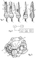
- a first vehicle 1 is in the crossing phase of a second vehicle 2 progressing on a traffic lane in the opposite direction. It is necessary not to dazzle the driver of the second vehicle 2, and nevertheless seek to optimize the illumination of the environment surrounding the first vehicle 1.
- the projector of the first vehicle emits beams of straight road 3 and left 4 which are restricted in lateral amplitude (so-called ALR beams for the sake of brevity in the rest of the text), to create a shadow zone 5 in the space occupied by the second vehicle 2, while optimizing the lighting of the surrounding area.
- the emission of the left-side beam 4 whose lateral amplitude is restricted is gradually tilted to the left in order to avoid dazzling the driver of the second vehicle 2 in the approach situation.
- the left optical module of the first vehicle 1 emits a code beam 6 when the second vehicle 2 arrives nearby.
- the right and left optical modules of the first vehicle 1 both emit road beams 3 ', 4' without side lighting restrictions.
- the illumination of the area surrounding the first vehicle 1 is optimized, without causing glare to the driver of the second vehicle 2, on the one hand from a lateral restriction of the road beams emitted by the at least one optical module equipping the first vehicle 1, and secondly from the switching of the light beam 4 emitted by the left optical module.
- the optical module uses detection means 7, such as optoelectronic means or the like, which are associated with calculation means 8.
- the optical module also implements lighting function control means 9 dedicated to the emission of the light beams by the right and left optical modules of the first vehicle 1.
- the lighting functions combine a rotating beam device 10, a mechanism 11 for selecting the emission of a specific light beam, and a mechanism attitude correction 12, or even a mechanism for raising the cross beams emitted by the optical modules.
- Each of these lighting functions 10, 11, 12 can be implemented independently of one optical module to the other equipping the first vehicle 1, according to respective desired positions of movable covers that comprise the right optical modules. and left of the first vehicle 1.
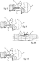
- the mechanism 11 for selecting the emission of a specific light beam comprises a movable cover which is arranged in a shaft 13 rotatably mounted on a frame 14 integrated in a housing 15 of the optical modules 16. More particularly on the fig.8 to fig.10 , the housing 15 houses a lighting module associating a light source 17 and an optical system composed of a reflector 18 and a lens 19.
- the Figures 8 to 10 represent the optical modules which are intended to be subsequently integrated into a lighting device or projector.
- the rotating axis 13 is interposed between the light source 17 and the lens 19, to modify the range and / or the lateral amplitude of the light beam emitted by the optical module 16.
- the rotating axis 13 is represented in the intermediate emission position of a coded beam by the optical module 16.
- the rotating axis 13 is able to be rotated by means of a motor 20, preferably a direct current, by via a transmission mechanism associating gear wheels 21,22.
- the rotating axis 13 is automatically placed in the emission position of a code beam 6 by the optical module 16, from an electrical control modification of the motor 20 and a spontaneous drive of the rotating shaft 13 to means of an elastic return member 23, such as a torsion spring or the like.
- the elastic return member 23 is stressed, so that its release causes spontaneously the positioning of the rotating shaft 13 for the emission of the code beam 6 by the optical module 16.
- the motor member 20 is provided for driving the rotating shaft 13 according to one and the other of its directions of rotation, to stable additional light beam emission positions, including a 3 ';4' beam and a narrow lateral amplitude beam 3.4.
- Maintaining the rotating axis 13 in each of its stable positions corresponding to the emission of the different light beams is obtained from a system of stops against an activation of the motor member 20 for the positions corresponding to the emission of the additional light beams 3,4; 3 ', 4' and against the return member 23 for the emission of the beam code 6.
- FIG. 6 and fig.7 are represented rotating shafts 13 respectively assigned to a left optical module and a right optical module equipping the first vehicle.
- These rotating shafts 13 have a constant overall profile of rectangular conformation.
- Each of these rotating shafts 13 comprises a first cutoff member 24 which is arranged in a double top-edge cache (for more details on this type of double cache, can refer, for example, to the patent EP-1,584,862 ).
- the first cut-off member 24 induces an oblique cut-off line of the light beam emitted by the optical module 16, for the emission of the code beam 6.
- the first cut-off member 24 is automatically placed in an intermediate focusing position on the optical axis of the lighting module under the effect of the return member 23, with which the rotating shaft 13 is engaged.
- one of the ends of the rotating shafts 13 comprises a shaft 25 for receiving the return member 23 on which it is threaded. At this same end is provided a groove 26 along which guides 27 which the frame 14, as visible on the fig.5 .
- a stop system 28 with two positions of the rotating shafts cooperates with counter-stops that the frame 14 has to hold the rotating shafts 13 in their various respective positions.
- an arm 29 allows the pre-positioning of the elastic return member 23.
- each of the rotary axes 13 comprises a second cutoff member 30 arranged in a wall, which is laterally shifted to the right for the rotating axis 13 assigned to the left optical module and to the left for the rotating axis 13 assigned to the module right optics.
- Such offsets are to be considered with regard to the position of the optical axis of the lighting module.
- These walls 30 are of height (substantially) constant, being angularly offset with respect to the corresponding first cutoff member 24, an angle of the order between 100 ° and 110 °.
- the walls 30 in the active position are able to induce from their side edge 31 closest to the optical axis of the lighting module, a cut of the lateral amplitude of a driving beam emitted by the optical module.
- the active position of the wall 30 its position corresponding to its focus on the axis of the lighting module.
- This active position of the wall 30 results from the driving of the rotating shaft 13 in the corresponding direction of rotation.
- the position of the crown edge 32 of the wall 30 corresponds to the position of the crown edge 24 'of the first cutoff member 24.
- the wall 30 induces not only a cutoff lateral amplitude of the 3.4 beam, but also an upward cut corresponding to an emission cutoff of a beam code 6.
- the cut lines in rise are of the order of 0.54 mm.
- the rotating axis 13 is in the spontaneous emission position of a code beam 6.
- the motor member 20 is deactivated and the return member 23 causes the rotating axis 13 to pass from any other position an additional light beam 3,4; 3 ', 4' emitted by the optical module 16 to its intermediate position corresponding to the emission of a code beam 6.
- the first cutoff member 24 is stably held by the elastic return member 23
- the first cut-off member 24 is active, and the range of the light beam emitted by the optical module 16 is limited upwards by the apex stop 24 'of the first cut-off member 24 for the emission of a code 6 beam. .
- the rotating shaft 13 is rotated in a first direction until it is immobilized and maintained in stability against a first abutment member.
- This rotating maneuver places the wall 30 in the active position of restriction of the lateral amplitude of a road beam 3,4 emitted by the optical module 16, and in the up-cut position in this zone of lateral cutoff.
- the light beam 33 emitted by a right optical module corresponds to a narrow amplitude road beam 3.4, both laterally 34 through the edge 31 of the wall 30 closest to the optical axis A of the module lighting up 35 in the same zone 36 of vertical amplitude cut 34 of the driving beam.
- the area to be illuminated surrounding the first vehicle 1 is optimized by restricting light emission to a space 5 in which the presence of the second vehicle 2 is detected. From a variation of inclination of the lighting module or the optical module through the turn turning functions 10 and / or attitude correction 12, this space 5 preserved lighting can evolve depending on the evolution of the second vehicle 2 whose driver must not be dazzled.
- the rotating shaft 13 is operated in a direction of rotation opposite to the previous one, until it is immobilized and maintained in stability while bearing against a second abutment member. In the absence of detection of a second vehicle 2, this rotating maneuver places the rotating shaft 13 so as to clear the light beam emitted by the optical module 16, to optimize the illumination of the environment of the first vehicle 1 by the emission of a driving beam 3 ', 4'.
Landscapes
- Engineering & Computer Science (AREA)
- General Engineering & Computer Science (AREA)
- Mechanical Engineering (AREA)
- Lighting Device Outwards From Vehicle And Optical Signal (AREA)
- Non-Portable Lighting Devices Or Systems Thereof (AREA)
Applications Claiming Priority (2)
| Application Number | Priority Date | Filing Date | Title |
|---|---|---|---|
| FR0805409A FR2936591B1 (fr) | 2008-09-30 | 2008-09-30 | Module optique pour vehicule automobile apte a eclairer selectivement une zone |
| EP09171704.1A EP2169299B1 (de) | 2008-09-30 | 2009-09-29 | Optisches Modul für ein Kraftfahrzeug, das selektiv eine Zone beleuchten kann |
Related Parent Applications (2)
| Application Number | Title | Priority Date | Filing Date |
|---|---|---|---|
| EP09171704.1A Division EP2169299B1 (de) | 2008-09-30 | 2009-09-29 | Optisches Modul für ein Kraftfahrzeug, das selektiv eine Zone beleuchten kann |
| EP09171704.1A Division-Into EP2169299B1 (de) | 2008-09-30 | 2009-09-29 | Optisches Modul für ein Kraftfahrzeug, das selektiv eine Zone beleuchten kann |
Publications (2)
| Publication Number | Publication Date |
|---|---|
| EP3045806A1 true EP3045806A1 (de) | 2016-07-20 |
| EP3045806B1 EP3045806B1 (de) | 2019-05-01 |
Family
ID=40459602
Family Applications (2)
| Application Number | Title | Priority Date | Filing Date |
|---|---|---|---|
| EP16156636.9A Active EP3045806B1 (de) | 2008-09-30 | 2009-09-29 | Optisches modul für ein kraftfahrzeug, das selektiv eine zone beleuchten kann |
| EP09171704.1A Active EP2169299B1 (de) | 2008-09-30 | 2009-09-29 | Optisches Modul für ein Kraftfahrzeug, das selektiv eine Zone beleuchten kann |
Family Applications After (1)
| Application Number | Title | Priority Date | Filing Date |
|---|---|---|---|
| EP09171704.1A Active EP2169299B1 (de) | 2008-09-30 | 2009-09-29 | Optisches Modul für ein Kraftfahrzeug, das selektiv eine Zone beleuchten kann |
Country Status (5)
| Country | Link |
|---|---|
| US (1) | US8348485B2 (de) |
| EP (2) | EP3045806B1 (de) |
| JP (1) | JP5670629B2 (de) |
| DE (3) | DE09171704T1 (de) |
| FR (1) | FR2936591B1 (de) |
Families Citing this family (17)
| Publication number | Priority date | Publication date | Assignee | Title |
|---|---|---|---|---|
| DE102008047025A1 (de) * | 2008-09-13 | 2010-03-18 | Hella Kgaa Hueck & Co. | Verfahren und Vorrichtung zum Steuern von vertikalen Hell-Dunkel-Grenzen bei Scheinwerfern innerhalb eines Schwenkbereichs |
| FR2957032B1 (fr) * | 2010-03-05 | 2016-05-27 | Valeo Vision | Systeme optique pour vehicule automobile |
| AT509829B1 (de) * | 2010-04-22 | 2012-09-15 | Zizala Lichtsysteme Gmbh | Scheinwerfer für fahrzeuge |
| AT509816B1 (de) * | 2010-04-22 | 2012-07-15 | Zizala Lichtsysteme Gmbh | Scheinwerfer für fahrzeuge |
| AT509830B1 (de) * | 2010-04-22 | 2012-07-15 | Zizala Lichtsysteme Gmbh | Scheinwerfer für fahrzeuge |
| DE102010035636B4 (de) * | 2010-08-27 | 2024-10-10 | HELLA GmbH & Co. KGaA | Vorrichtung zum Wechseln von einer Fernlichtverteilung zu einer ein zu entblendendes Objekt entblendenden Lichtverteilung |
| FR2975646B1 (fr) * | 2011-05-25 | 2015-06-26 | Aml Systems | Projecteur pour vehicule automobile |
| DE102012103318A1 (de) * | 2012-04-17 | 2013-10-17 | Hella Kgaa Hueck & Co. | Verfahren für die Veränderung einer Ausleuchtsituation vor einem vor einem Fahrzeug |
| JP5949085B2 (ja) * | 2012-04-20 | 2016-07-06 | 市光工業株式会社 | 車両用前照灯の配光制御システム |
| FR2999273B1 (fr) * | 2012-12-06 | 2015-01-23 | Valeo Vision | Dispositif d'eclairage et/ou de signalisation pour vehicule automobile, comprenant un cache rotatif |
| DE102012112598A1 (de) | 2012-12-19 | 2014-06-26 | Dr. Ing. H.C. F. Porsche Aktiengesellschaft | Beleuchtungseinrichtung |
| FR3009602B1 (fr) * | 2013-08-06 | 2015-08-28 | Aml Systems | Mecanisme de coupure de faisceau lumineux pour module optique et le module optique |
| DE102014204770A1 (de) * | 2014-02-06 | 2015-08-06 | Conti Temic Microelectronic Gmbh | Fahrerassistenzsystem |
| KR101704131B1 (ko) * | 2014-11-27 | 2017-02-07 | 현대자동차주식회사 | 자동차용 헤드램프 |
| FR3032159A1 (fr) * | 2015-01-30 | 2016-08-05 | Valeo Vision | Dispositif optique pour phare d'automobile |
| CN111981434B (zh) * | 2018-05-31 | 2021-11-30 | 亳州易泽信息科技有限公司 | 一种减弱会车时远光灯影响的汽车遮光罩的传动方法 |
| US12441231B2 (en) * | 2023-11-22 | 2025-10-14 | Toyota Motor Engineering & Manufacturing North America, Inc. | Systems and methods for extending sensor and lighting coverage between vehicles |
Citations (10)
| Publication number | Priority date | Publication date | Assignee | Title |
|---|---|---|---|---|
| EP0935728A1 (de) | 1997-09-06 | 1999-08-18 | Hella KG Hueck & Co. | Scheinwerfer für fahrzeuge |
| US20050201117A1 (en) * | 2004-03-12 | 2005-09-15 | Atsushi Sugimoto | Projector type vehicle headlamp |
| EP1584862A1 (de) | 2004-04-09 | 2005-10-12 | Valeo Vision | Scheinwerfer für Abblendlicht mit Blende |
| DE102004033737A1 (de) * | 2004-07-13 | 2006-02-16 | Adam Opel Ag | Scheinwerfer mit einer drehbaren Blendenwelle |
| EP1806531A1 (de) * | 2006-01-05 | 2007-07-11 | Valeo Vision | Multifunktionales, elliptisches Scheinwerfergerät mit zusätzlichem, optischem Element |
| EP1818602A2 (de) * | 2006-02-14 | 2007-08-15 | Valeo Vision | Beleuchtungsscheinwerfer für Kraftfahrzeuge |
| US20070217194A1 (en) * | 2006-03-17 | 2007-09-20 | Sl Corporation | Rotary lamp shield driving device for providing a plurality of beam radiation patterns, and lamp assembly using the same |
| DE102006043281A1 (de) | 2006-09-14 | 2008-03-27 | Hella Kgaa Hueck & Co. | Projektionsscheinwerferanordnung für Fahrzeuge |
| WO2008037388A2 (de) * | 2006-09-27 | 2008-04-03 | Volkswagen Aktiengesellschaft | Scheinwerferanordnung für ein fahrzeug und verfahren zum steuern einer scheinwerferanordnung |
| EP1923262A1 (de) | 2006-11-17 | 2008-05-21 | Valeo Vision | Verfahren zur automatischen Anpassung eines Leuchtstrahls eines Projektors |
Family Cites Families (10)
| Publication number | Priority date | Publication date | Assignee | Title |
|---|---|---|---|---|
| JP2548801Y2 (ja) * | 1991-10-08 | 1997-09-24 | 株式会社小糸製作所 | 投射型自動車用ヘッドランプ |
| JP2577070Y2 (ja) * | 1992-06-05 | 1998-07-23 | 株式会社小糸製作所 | 投射型自動車用ヘッドランプ |
| JPH0741809U (ja) * | 1993-12-27 | 1995-07-21 | 株式会社小糸製作所 | 自動車用ヘッドランプ |
| JP3967153B2 (ja) * | 2002-03-04 | 2007-08-29 | 株式会社小糸製作所 | 車両用前照灯 |
| JP2005243349A (ja) * | 2004-02-25 | 2005-09-08 | Koito Mfg Co Ltd | 投射型自動車用ヘッドランプ |
| JP2006202694A (ja) * | 2005-01-24 | 2006-08-03 | Koito Mfg Co Ltd | 車両用前照灯 |
| JP2007214074A (ja) * | 2006-02-13 | 2007-08-23 | Stanley Electric Co Ltd | 車両前照灯 |
| US7736037B2 (en) * | 2006-06-02 | 2010-06-15 | Visteon Global Technologies, Inc. | Bi-functional lighting mechanism based on rotary actuator |
| JP4714108B2 (ja) * | 2006-08-09 | 2011-06-29 | 株式会社小糸製作所 | 車両用赤外光照射ランプ |
| JP5112218B2 (ja) * | 2008-08-08 | 2013-01-09 | 株式会社小糸製作所 | 車輌用前照灯 |
-
2008
- 2008-09-30 FR FR0805409A patent/FR2936591B1/fr active Active
-
2009
- 2009-09-29 DE DE09171704.1T patent/DE09171704T1/de active Pending
- 2009-09-29 EP EP16156636.9A patent/EP3045806B1/de active Active
- 2009-09-29 EP EP09171704.1A patent/EP2169299B1/de active Active
- 2009-09-29 DE DE202009019052.8U patent/DE202009019052U1/de not_active Expired - Lifetime
- 2009-09-29 DE DE202009019171.0U patent/DE202009019171U1/de not_active Expired - Lifetime
- 2009-09-30 US US12/569,946 patent/US8348485B2/en not_active Expired - Fee Related
- 2009-09-30 JP JP2009228992A patent/JP5670629B2/ja active Active
Patent Citations (10)
| Publication number | Priority date | Publication date | Assignee | Title |
|---|---|---|---|---|
| EP0935728A1 (de) | 1997-09-06 | 1999-08-18 | Hella KG Hueck & Co. | Scheinwerfer für fahrzeuge |
| US20050201117A1 (en) * | 2004-03-12 | 2005-09-15 | Atsushi Sugimoto | Projector type vehicle headlamp |
| EP1584862A1 (de) | 2004-04-09 | 2005-10-12 | Valeo Vision | Scheinwerfer für Abblendlicht mit Blende |
| DE102004033737A1 (de) * | 2004-07-13 | 2006-02-16 | Adam Opel Ag | Scheinwerfer mit einer drehbaren Blendenwelle |
| EP1806531A1 (de) * | 2006-01-05 | 2007-07-11 | Valeo Vision | Multifunktionales, elliptisches Scheinwerfergerät mit zusätzlichem, optischem Element |
| EP1818602A2 (de) * | 2006-02-14 | 2007-08-15 | Valeo Vision | Beleuchtungsscheinwerfer für Kraftfahrzeuge |
| US20070217194A1 (en) * | 2006-03-17 | 2007-09-20 | Sl Corporation | Rotary lamp shield driving device for providing a plurality of beam radiation patterns, and lamp assembly using the same |
| DE102006043281A1 (de) | 2006-09-14 | 2008-03-27 | Hella Kgaa Hueck & Co. | Projektionsscheinwerferanordnung für Fahrzeuge |
| WO2008037388A2 (de) * | 2006-09-27 | 2008-04-03 | Volkswagen Aktiengesellschaft | Scheinwerferanordnung für ein fahrzeug und verfahren zum steuern einer scheinwerferanordnung |
| EP1923262A1 (de) | 2006-11-17 | 2008-05-21 | Valeo Vision | Verfahren zur automatischen Anpassung eines Leuchtstrahls eines Projektors |
Also Published As
| Publication number | Publication date |
|---|---|
| FR2936591A1 (fr) | 2010-04-02 |
| EP3045806B1 (de) | 2019-05-01 |
| JP2010103108A (ja) | 2010-05-06 |
| FR2936591B1 (fr) | 2014-09-12 |
| DE202009019052U1 (de) | 2015-12-18 |
| EP2169299A1 (de) | 2010-03-31 |
| DE09171704T1 (de) | 2016-09-08 |
| US8348485B2 (en) | 2013-01-08 |
| JP5670629B2 (ja) | 2015-02-18 |
| EP2169299B1 (de) | 2018-01-24 |
| US20100091514A1 (en) | 2010-04-15 |
| DE202009019171U1 (de) | 2017-07-07 |
Similar Documents
| Publication | Publication Date | Title |
|---|---|---|
| EP3045806B1 (de) | Optisches modul für ein kraftfahrzeug, das selektiv eine zone beleuchten kann | |
| EP2665625B1 (de) | Modul zur projektion eines lichtstrahls | |
| EP2902701B1 (de) | Drehbares Beleuchtungs- und/oder Signalisierungsmodul mit feststehender Lichtquelle | |
| EP3181991B1 (de) | Kraftfahrzeug-beleuchtungsmodul mit kombinerter abblend- und fernlichtfunktion und einer regulierbaren lichtquelle | |
| EP2957464B1 (de) | Drehbares beleuchtungs- und/oder signalisierungsmodul | |
| EP2006605B1 (de) | Fahrzeugsscheinwerfer | |
| FR2834110A1 (fr) | Dispositif d'aide a la conduite pour vehicule automobile optimise par synergie avec un eclairage adaptatif | |
| EP3045807A1 (de) | Optische vorrichtung für kraftfahrzeug | |
| EP2799286B1 (de) | Drehbar und multifunktionnale Modul für Signalisierung und/or für Beleuchtung | |
| EP2988972B1 (de) | Verfahren zur steuerung eines regulierbaren beleuchtungssystems für ein trägerfahrzeug und reguliebares beleuchtungsystem | |
| EP2436968B1 (de) | Vorrichtung zur Ausstrahlung von Licht für einen Autoscheinwerfer | |
| EP1684004B1 (de) | Fahrzeugscheinwerfer mit zwei Beleuchtungsverteilungen | |
| EP2168812B1 (de) | Beleuchtungssystem für ein kraftfahrzeug, das die emission eines abblendlichts verändern kann | |
| EP2366587A1 (de) | Optisches System für Kraftfahrzeug | |
| EP3455102B1 (de) | Beleuchtungssystem und verfahren für ein kraftfahrzeug | |
| EP1870283B1 (de) | Scheinwerfereinheit mit drei Funktionen für Kraftfahrzeuge | |
| EP2957820B1 (de) | Drehbares beleuchtungs- und/oder signalisierungsmodul | |
| FR2759651A1 (fr) | Projecteur de vehicule automobile comportant un reflecteur fractionne en lames orientables | |
| EP3436307B1 (de) | Fahrzeugscheinwerfer | |
| EP1619440A1 (de) | Beleuchtungssystem für Kraftfahrzeuge mit Überlappung von Lichtbündeln | |
| FR3116103A1 (fr) | Dispositif d’éclairage adaptatif comportant un module tournant, et véhicule ainsi équipé. | |
| EP1870634A1 (de) | Scheinwerfer mit mehreren Leuchtfunktionen, insbesondere für Kraftfahrzeuge | |
| EP1953039A2 (de) | Multifunktionsbeleuchtungsvorrichtung für Kraftfahrzeug | |
| EP2196731A1 (de) | Optisches Scheinwerfermodul für Kraftfahrzeug mit mobiler Abdeckung | |
| EP2947379A2 (de) | Elliptisches optisches modul für beleuchtungsvorrichtung eines kraftfahrzeugs |
Legal Events
| Date | Code | Title | Description |
|---|---|---|---|
| PUAI | Public reference made under article 153(3) epc to a published international application that has entered the european phase |
Free format text: ORIGINAL CODE: 0009012 |
|
| AC | Divisional application: reference to earlier application |
Ref document number: 2169299 Country of ref document: EP Kind code of ref document: P |
|
| AK | Designated contracting states |
Kind code of ref document: A1 Designated state(s): AT BE BG CH CY CZ DE DK EE ES FI FR GB GR HR HU IE IS IT LI LT LU LV MC MK MT NL NO PL PT RO SE SI SK SM TR |
|
| STAA | Information on the status of an ep patent application or granted ep patent |
Free format text: STATUS: REQUEST FOR EXAMINATION WAS MADE |
|
| 17P | Request for examination filed |
Effective date: 20161216 |
|
| RBV | Designated contracting states (corrected) |
Designated state(s): AT BE BG CH CY CZ DE DK EE ES FI FR GB GR HR HU IE IS IT LI LT LU LV MC MK MT NL NO PL PT RO SE SI SK SM TR |
|
| REG | Reference to a national code |
Ref country code: DE Ref legal event code: R079 Ref document number: 602009058194 Country of ref document: DE Free format text: PREVIOUS MAIN CLASS: F21V0014080000 Ipc: F21S0041683000 |
|
| GRAP | Despatch of communication of intention to grant a patent |
Free format text: ORIGINAL CODE: EPIDOSNIGR1 |
|
| RIC1 | Information provided on ipc code assigned before grant |
Ipc: F21V 14/08 20060101ALI20181012BHEP Ipc: F21S 41/683 20160720AFI20181012BHEP |
|
| STAA | Information on the status of an ep patent application or granted ep patent |
Free format text: STATUS: GRANT OF PATENT IS INTENDED |
|
| INTG | Intention to grant announced |
Effective date: 20181122 |
|
| RIC1 | Information provided on ipc code assigned before grant |
Ipc: F21V 14/08 20060101ALI20181012BHEP Ipc: F21S 41/683 20180101AFI20181012BHEP |
|
| RIC1 | Information provided on ipc code assigned before grant |
Ipc: F21S 41/683 20180101AFI20181012BHEP Ipc: F21V 14/08 20060101ALI20181012BHEP |
|
| GRAS | Grant fee paid |
Free format text: ORIGINAL CODE: EPIDOSNIGR3 |
|
| GRAJ | Information related to disapproval of communication of intention to grant by the applicant or resumption of examination proceedings by the epo deleted |
Free format text: ORIGINAL CODE: EPIDOSDIGR1 |
|
| GRAL | Information related to payment of fee for publishing/printing deleted |
Free format text: ORIGINAL CODE: EPIDOSDIGR3 |
|
| STAA | Information on the status of an ep patent application or granted ep patent |
Free format text: STATUS: REQUEST FOR EXAMINATION WAS MADE |
|
| GRAR | Information related to intention to grant a patent recorded |
Free format text: ORIGINAL CODE: EPIDOSNIGR71 |
|
| STAA | Information on the status of an ep patent application or granted ep patent |
Free format text: STATUS: GRANT OF PATENT IS INTENDED |
|
| GRAA | (expected) grant |
Free format text: ORIGINAL CODE: 0009210 |
|
| STAA | Information on the status of an ep patent application or granted ep patent |
Free format text: STATUS: THE PATENT HAS BEEN GRANTED |
|
| INTC | Intention to grant announced (deleted) | ||
| AC | Divisional application: reference to earlier application |
Ref document number: 2169299 Country of ref document: EP Kind code of ref document: P |
|
| AK | Designated contracting states |
Kind code of ref document: B1 Designated state(s): AT BE BG CH CY CZ DE DK EE ES FI FR GB GR HR HU IE IS IT LI LT LU LV MC MK MT NL NO PL PT RO SE SI SK SM TR |
|
| INTG | Intention to grant announced |
Effective date: 20190326 |
|
| REG | Reference to a national code |
Ref country code: GB Ref legal event code: FG4D Free format text: NOT ENGLISH |
|
| REG | Reference to a national code |
Ref country code: CH Ref legal event code: EP Ref country code: AT Ref legal event code: REF Ref document number: 1127410 Country of ref document: AT Kind code of ref document: T Effective date: 20190515 |
|
| REG | Reference to a national code |
Ref country code: DE Ref legal event code: R096 Ref document number: 602009058194 Country of ref document: DE |
|
| REG | Reference to a national code |
Ref country code: IE Ref legal event code: FG4D Free format text: LANGUAGE OF EP DOCUMENT: FRENCH |
|
| REG | Reference to a national code |
Ref country code: NL Ref legal event code: MP Effective date: 20190501 |
|
| REG | Reference to a national code |
Ref country code: LT Ref legal event code: MG4D |
|
| PG25 | Lapsed in a contracting state [announced via postgrant information from national office to epo] |
Ref country code: FI Free format text: LAPSE BECAUSE OF FAILURE TO SUBMIT A TRANSLATION OF THE DESCRIPTION OR TO PAY THE FEE WITHIN THE PRESCRIBED TIME-LIMIT Effective date: 20190501 Ref country code: LT Free format text: LAPSE BECAUSE OF FAILURE TO SUBMIT A TRANSLATION OF THE DESCRIPTION OR TO PAY THE FEE WITHIN THE PRESCRIBED TIME-LIMIT Effective date: 20190501 Ref country code: NL Free format text: LAPSE BECAUSE OF FAILURE TO SUBMIT A TRANSLATION OF THE DESCRIPTION OR TO PAY THE FEE WITHIN THE PRESCRIBED TIME-LIMIT Effective date: 20190501 Ref country code: ES Free format text: LAPSE BECAUSE OF FAILURE TO SUBMIT A TRANSLATION OF THE DESCRIPTION OR TO PAY THE FEE WITHIN THE PRESCRIBED TIME-LIMIT Effective date: 20190501 Ref country code: HR Free format text: LAPSE BECAUSE OF FAILURE TO SUBMIT A TRANSLATION OF THE DESCRIPTION OR TO PAY THE FEE WITHIN THE PRESCRIBED TIME-LIMIT Effective date: 20190501 Ref country code: NO Free format text: LAPSE BECAUSE OF FAILURE TO SUBMIT A TRANSLATION OF THE DESCRIPTION OR TO PAY THE FEE WITHIN THE PRESCRIBED TIME-LIMIT Effective date: 20190801 Ref country code: SE Free format text: LAPSE BECAUSE OF FAILURE TO SUBMIT A TRANSLATION OF THE DESCRIPTION OR TO PAY THE FEE WITHIN THE PRESCRIBED TIME-LIMIT Effective date: 20190501 Ref country code: PT Free format text: LAPSE BECAUSE OF FAILURE TO SUBMIT A TRANSLATION OF THE DESCRIPTION OR TO PAY THE FEE WITHIN THE PRESCRIBED TIME-LIMIT Effective date: 20190901 |
|
| PG25 | Lapsed in a contracting state [announced via postgrant information from national office to epo] |
Ref country code: LV Free format text: LAPSE BECAUSE OF FAILURE TO SUBMIT A TRANSLATION OF THE DESCRIPTION OR TO PAY THE FEE WITHIN THE PRESCRIBED TIME-LIMIT Effective date: 20190501 Ref country code: GR Free format text: LAPSE BECAUSE OF FAILURE TO SUBMIT A TRANSLATION OF THE DESCRIPTION OR TO PAY THE FEE WITHIN THE PRESCRIBED TIME-LIMIT Effective date: 20190802 Ref country code: BG Free format text: LAPSE BECAUSE OF FAILURE TO SUBMIT A TRANSLATION OF THE DESCRIPTION OR TO PAY THE FEE WITHIN THE PRESCRIBED TIME-LIMIT Effective date: 20190801 |
|
| REG | Reference to a national code |
Ref country code: AT Ref legal event code: MK05 Ref document number: 1127410 Country of ref document: AT Kind code of ref document: T Effective date: 20190501 |
|
| PG25 | Lapsed in a contracting state [announced via postgrant information from national office to epo] |
Ref country code: IS Free format text: LAPSE BECAUSE OF FAILURE TO SUBMIT A TRANSLATION OF THE DESCRIPTION OR TO PAY THE FEE WITHIN THE PRESCRIBED TIME-LIMIT Effective date: 20190901 |
|
| PG25 | Lapsed in a contracting state [announced via postgrant information from national office to epo] |
Ref country code: CZ Free format text: LAPSE BECAUSE OF FAILURE TO SUBMIT A TRANSLATION OF THE DESCRIPTION OR TO PAY THE FEE WITHIN THE PRESCRIBED TIME-LIMIT Effective date: 20190501 Ref country code: RO Free format text: LAPSE BECAUSE OF FAILURE TO SUBMIT A TRANSLATION OF THE DESCRIPTION OR TO PAY THE FEE WITHIN THE PRESCRIBED TIME-LIMIT Effective date: 20190501 Ref country code: SK Free format text: LAPSE BECAUSE OF FAILURE TO SUBMIT A TRANSLATION OF THE DESCRIPTION OR TO PAY THE FEE WITHIN THE PRESCRIBED TIME-LIMIT Effective date: 20190501 Ref country code: DK Free format text: LAPSE BECAUSE OF FAILURE TO SUBMIT A TRANSLATION OF THE DESCRIPTION OR TO PAY THE FEE WITHIN THE PRESCRIBED TIME-LIMIT Effective date: 20190501 Ref country code: AT Free format text: LAPSE BECAUSE OF FAILURE TO SUBMIT A TRANSLATION OF THE DESCRIPTION OR TO PAY THE FEE WITHIN THE PRESCRIBED TIME-LIMIT Effective date: 20190501 Ref country code: EE Free format text: LAPSE BECAUSE OF FAILURE TO SUBMIT A TRANSLATION OF THE DESCRIPTION OR TO PAY THE FEE WITHIN THE PRESCRIBED TIME-LIMIT Effective date: 20190501 |
|
| REG | Reference to a national code |
Ref country code: DE Ref legal event code: R097 Ref document number: 602009058194 Country of ref document: DE |
|
| PG25 | Lapsed in a contracting state [announced via postgrant information from national office to epo] |
Ref country code: IT Free format text: LAPSE BECAUSE OF FAILURE TO SUBMIT A TRANSLATION OF THE DESCRIPTION OR TO PAY THE FEE WITHIN THE PRESCRIBED TIME-LIMIT Effective date: 20190501 Ref country code: SM Free format text: LAPSE BECAUSE OF FAILURE TO SUBMIT A TRANSLATION OF THE DESCRIPTION OR TO PAY THE FEE WITHIN THE PRESCRIBED TIME-LIMIT Effective date: 20190501 |
|
| PLBE | No opposition filed within time limit |
Free format text: ORIGINAL CODE: 0009261 |
|
| STAA | Information on the status of an ep patent application or granted ep patent |
Free format text: STATUS: NO OPPOSITION FILED WITHIN TIME LIMIT |
|
| PG25 | Lapsed in a contracting state [announced via postgrant information from national office to epo] |
Ref country code: TR Free format text: LAPSE BECAUSE OF FAILURE TO SUBMIT A TRANSLATION OF THE DESCRIPTION OR TO PAY THE FEE WITHIN THE PRESCRIBED TIME-LIMIT Effective date: 20190501 |
|
| 26N | No opposition filed |
Effective date: 20200204 |
|
| PG25 | Lapsed in a contracting state [announced via postgrant information from national office to epo] |
Ref country code: PL Free format text: LAPSE BECAUSE OF FAILURE TO SUBMIT A TRANSLATION OF THE DESCRIPTION OR TO PAY THE FEE WITHIN THE PRESCRIBED TIME-LIMIT Effective date: 20190501 |
|
| PG25 | Lapsed in a contracting state [announced via postgrant information from national office to epo] |
Ref country code: SI Free format text: LAPSE BECAUSE OF FAILURE TO SUBMIT A TRANSLATION OF THE DESCRIPTION OR TO PAY THE FEE WITHIN THE PRESCRIBED TIME-LIMIT Effective date: 20190501 Ref country code: MC Free format text: LAPSE BECAUSE OF FAILURE TO SUBMIT A TRANSLATION OF THE DESCRIPTION OR TO PAY THE FEE WITHIN THE PRESCRIBED TIME-LIMIT Effective date: 20190501 |
|
| REG | Reference to a national code |
Ref country code: CH Ref legal event code: PL |
|
| PG25 | Lapsed in a contracting state [announced via postgrant information from national office to epo] |
Ref country code: CH Free format text: LAPSE BECAUSE OF NON-PAYMENT OF DUE FEES Effective date: 20190930 Ref country code: LU Free format text: LAPSE BECAUSE OF NON-PAYMENT OF DUE FEES Effective date: 20190929 Ref country code: IE Free format text: LAPSE BECAUSE OF NON-PAYMENT OF DUE FEES Effective date: 20190929 Ref country code: LI Free format text: LAPSE BECAUSE OF NON-PAYMENT OF DUE FEES Effective date: 20190930 |
|
| REG | Reference to a national code |
Ref country code: BE Ref legal event code: MM Effective date: 20190930 |
|
| PG25 | Lapsed in a contracting state [announced via postgrant information from national office to epo] |
Ref country code: BE Free format text: LAPSE BECAUSE OF NON-PAYMENT OF DUE FEES Effective date: 20190930 |
|
| GBPC | Gb: european patent ceased through non-payment of renewal fee |
Effective date: 20190929 |
|
| PG25 | Lapsed in a contracting state [announced via postgrant information from national office to epo] |
Ref country code: GB Free format text: LAPSE BECAUSE OF NON-PAYMENT OF DUE FEES Effective date: 20190929 |
|
| PG25 | Lapsed in a contracting state [announced via postgrant information from national office to epo] |
Ref country code: CY Free format text: LAPSE BECAUSE OF FAILURE TO SUBMIT A TRANSLATION OF THE DESCRIPTION OR TO PAY THE FEE WITHIN THE PRESCRIBED TIME-LIMIT Effective date: 20190501 |
|
| PG25 | Lapsed in a contracting state [announced via postgrant information from national office to epo] |
Ref country code: HU Free format text: LAPSE BECAUSE OF FAILURE TO SUBMIT A TRANSLATION OF THE DESCRIPTION OR TO PAY THE FEE WITHIN THE PRESCRIBED TIME-LIMIT; INVALID AB INITIO Effective date: 20090929 Ref country code: MT Free format text: LAPSE BECAUSE OF FAILURE TO SUBMIT A TRANSLATION OF THE DESCRIPTION OR TO PAY THE FEE WITHIN THE PRESCRIBED TIME-LIMIT Effective date: 20190501 |
|
| PG25 | Lapsed in a contracting state [announced via postgrant information from national office to epo] |
Ref country code: MK Free format text: LAPSE BECAUSE OF FAILURE TO SUBMIT A TRANSLATION OF THE DESCRIPTION OR TO PAY THE FEE WITHIN THE PRESCRIBED TIME-LIMIT Effective date: 20190501 |
|
| P01 | Opt-out of the competence of the unified patent court (upc) registered |
Effective date: 20230528 |
|
| PGFP | Annual fee paid to national office [announced via postgrant information from national office to epo] |
Ref country code: DE Payment date: 20250916 Year of fee payment: 17 |
|
| PGFP | Annual fee paid to national office [announced via postgrant information from national office to epo] |
Ref country code: FR Payment date: 20250929 Year of fee payment: 17 |