EP3045877A1 - Procédé de fonctionnement d'un appareil de mesure de débit massique coriolis - Google Patents
Procédé de fonctionnement d'un appareil de mesure de débit massique coriolis Download PDFInfo
- Publication number
- EP3045877A1 EP3045877A1 EP15195810.5A EP15195810A EP3045877A1 EP 3045877 A1 EP3045877 A1 EP 3045877A1 EP 15195810 A EP15195810 A EP 15195810A EP 3045877 A1 EP3045877 A1 EP 3045877A1
- Authority
- EP
- European Patent Office
- Prior art keywords
- measuring tube
- temperature
- coil
- coriolis mass
- mass flowmeter
- Prior art date
- Legal status (The legal status is an assumption and is not a legal conclusion. Google has not performed a legal analysis and makes no representation as to the accuracy of the status listed.)
- Granted
Links
Images


Classifications
-
- G—PHYSICS
- G01—MEASURING; TESTING
- G01F—MEASURING VOLUME, VOLUME FLOW, MASS FLOW OR LIQUID LEVEL; METERING BY VOLUME
- G01F1/00—Measuring the volume flow or mass flow of fluid or fluent solid material wherein the fluid passes through a meter in a continuous flow
- G01F1/76—Devices for measuring mass flow of a fluid or a fluent solid material
- G01F1/78—Direct mass flowmeters
- G01F1/80—Direct mass flowmeters operating by measuring pressure, force, momentum, or frequency of a fluid flow to which a rotational movement has been imparted
- G01F1/84—Coriolis or gyroscopic mass flowmeters
- G01F1/845—Coriolis or gyroscopic mass flowmeters arrangements of measuring means, e.g., of measuring conduits
- G01F1/8468—Coriolis or gyroscopic mass flowmeters arrangements of measuring means, e.g., of measuring conduits vibrating measuring conduits
- G01F1/849—Coriolis or gyroscopic mass flowmeters arrangements of measuring means, e.g., of measuring conduits vibrating measuring conduits having straight measuring conduits
- G01F1/8495—Coriolis or gyroscopic mass flowmeters arrangements of measuring means, e.g., of measuring conduits vibrating measuring conduits having straight measuring conduits with multiple measuring conduits
-
- G—PHYSICS
- G01—MEASURING; TESTING
- G01F—MEASURING VOLUME, VOLUME FLOW, MASS FLOW OR LIQUID LEVEL; METERING BY VOLUME
- G01F1/00—Measuring the volume flow or mass flow of fluid or fluent solid material wherein the fluid passes through a meter in a continuous flow
- G01F1/76—Devices for measuring mass flow of a fluid or a fluent solid material
- G01F1/78—Direct mass flowmeters
- G01F1/80—Direct mass flowmeters operating by measuring pressure, force, momentum, or frequency of a fluid flow to which a rotational movement has been imparted
- G01F1/84—Coriolis or gyroscopic mass flowmeters
- G01F1/8409—Coriolis or gyroscopic mass flowmeters constructional details
- G01F1/8436—Coriolis or gyroscopic mass flowmeters constructional details signal processing
-
- G—PHYSICS
- G01—MEASURING; TESTING
- G01F—MEASURING VOLUME, VOLUME FLOW, MASS FLOW OR LIQUID LEVEL; METERING BY VOLUME
- G01F15/00—Details of, or accessories for, apparatus of groups G01F1/00 - G01F13/00 insofar as such details or appliances are not adapted to particular types of such apparatus
- G01F15/02—Compensating or correcting for variations in pressure, density or temperature
- G01F15/022—Compensating or correcting for variations in pressure, density or temperature using electrical means
Definitions
- the invention relates to a method for operating a Coriolis mass flowmeter, wherein the Coriolis mass flowmeter has at least one measuring tube, at least one vibration generator, at least two vibration sensors and at least one evaluation device, wherein the vibration sensor and / or the vibration generator in each case at least one permanent magnet and at least one Coil comprise, wherein the vibration generator excites the measuring tube to vibrations, wherein the vibration sensor detect the vibrations of the measuring tube, wherein the temperature of the measuring tube is determined and wherein the evaluation device processes the detected vibration signals and determines state variables of the Coriolis mass flowmeter.
- Coriolis mass flowmeters are known in the art in a variety of configurations.
- Mass flowmeters that operate according to the Coriolis principle have at least one vibration generator with which the measuring tube is excited to vibrate - or possibly several measuring tubes are excited to vibrate - and at least two vibration sensors with which the vibration obtained or the vibrations obtained of the measuring tube are detected on.
- the vibration sensors are mounted on the inlet and outlet side of the measuring tube. If the measuring tube is set in oscillation, in the event that a medium-laden medium flows through the measuring tube, there are oscillation components which are influenced in opposite directions on the inlet and outlet sides and which are detected by the vibration sensors. Without flow, the signals of the two vibration sensors are ideally in phase. The reason for the increasing and decreasing mass flow resulting increasing different vibration components on the inlet and outlet side are differently directed Coriolis forces on the flowing medium.
- Vibration generators of Coriolis mass flowmeters of the aforementioned type comprise a coil and a permanent magnet.
- the permanent magnet is arranged in the area of influence of the coil such that the magnetic field generated when the coil is energized with the magnetic field of the permanent magnet interacts and corresponding forces on coil and permanent magnets act.
- the magnitude of the electrical current applied to the coil is decisive for the force that is transmitted from the vibration generator to the measuring tube and that causes the measuring tube to vibrate;
- the energization of the coil is usually harmonious and thus the application of force to the measuring tube.
- the Coriolis mass flowmeter is considered as a dynamic system with the input variable excitation force and the output variable measuring tube deflection - or a time-derived variable such as the measuring tube velocity - information on the identification of the transmission behavior of the dynamic system Coriolis is available with known excitation force and metrologically measured measuring tube velocity. Mass flowmeter before. If the identification is based on a mathematical model, it is possible to determine parameters used in the model, such as the spring stiffness of the measuring tube, the damping of the measuring tube and the oscillating total mass ( DE 10 2012 011 934 A1 . DE 10 2008 059 920 A1 ).
- the rigidity of the measuring tube is, among other things, temperature-dependent.
- the Applicant methods are known in which the measuring tube temperature is measured by a mounted on the measuring tube sensor, for example, to take into account the temperature dependence of the spring stiffness of the measuring tube.
- the invention is therefore based on the object to provide a method for operating a Coriolis mass flowmeter, which has a higher accuracy in the determination of state variables or values for state variables.
- the previously derived object is achieved in that the electrical impedance of the coil of the vibration generator and / or the electrical impedance of at least one coil of the vibration sensor are determined is and that the evaluation device calculates at least one temperature-dependent state variable D, wherein the temperature-dependent state variable D is corrected starting from the temperature of the measuring tube with the specific impedance of the coil.
- the state variable D may be a technical-physical quantity of the Coriolis mass flowmeter, but it may also be a fictitious characteristic variable which is suitable, for example, for monitoring a good state of the respective Coriolis mass flowmeter; such a fictitious characteristic size could be related to the spring stiffness of the measuring tube, without exactly mapping the spring stiffness itself.
- the method according to the invention makes it possible to compensate for temperature effects, which are associated, in particular, with the temperature dependence of the magnetization of the permanent magnets used here.
- M T M 0 1 - T T C 3 / 2
- M (T) is the magnetization of a permanent magnet
- M (0) is the magnetization at the temperature zero point.
- T denotes the temperature
- T c the Curie temperature. Since the strength of the magnet - its spontaneous magnetization - is decisive for the force transmitted by the vibrator, the magnet temperature also influences the accuracy of a calculated parameter or state variable.
- the coil resistance, or the electrical impedance of the coil provides a relationship that allows compensation of the influence of the magnet temperature. It is advantageous here that the coil whose impedance is detected, is functionally necessary in the immediate vicinity of its associated permanent magnet is arranged and Consequently, the temperature of the coil corresponds to a good approximation of the temperature of the permanent magnet. Since the impedance or the ohmic resistance of the coil are usually also variable in temperature, the detected impedance of the coil is a reliable indicator of the temperature of the coil and the temperature of the provided in the immediate vicinity permanent magnet.
- the correction of the state variable D takes place on the basis of at least one known temperature coefficient for describing the temperature dependence of the coil.
- a further embodiment of the method according to the invention provides that a reference value D ref of the state variable D is determined before the start-up of the Coriolis mass flowmeter in the ongoing process.
- a reference value D ref of the state variable D is determined before the start-up of the Coriolis mass flowmeter in the ongoing process.
- the device Before commissioning, it may mean that the device is already calibrated at the factory with a reference value. This can be stored in the device before delivery. It is also conceivable that the reference value in the installation situation in the process is determined on site if the Coriolis mass flowmeter has already been integrated into the process but has not yet been put into operation. In addition, it makes sense that the device is recalibrated even if the process conditions change, ie a new reference value can be calculated. Changing process conditions may be due to an expansion of the device or the integration of the device in a new process or, for example, by changing the medium flowing through.
- the reference value D ref is compared with a value D mess of the state variable D determined during operation.
- the operational value D mess can be determined at any interval or continuously.
- the ongoing Comparison with the reference value D ref makes it possible to make statements as to how far the current state of the Coriolis mass flowmeter corresponds to the original state at the time of the reference value determination.
- a signal from the evaluation device is output from the value D mess of the state variable D determined during operation.
- the signal may simply be the setting of a flag, such as setting a bit in a memory cell within the electronics of the Coriolis mass flowmeter.
- the signal can also be output electrically, acoustically or by means of a visualization via an interface of the Coriolis mass flowmeter.
- the signals can subsequently also be output in a higher-level control room, which clarify to the operator that the state of the measuring device has changed, for example, a good state is no longer present.
- the coefficients a 1 to a 3 , with a i ⁇ R . can be empirical and relate, for example, only to an individual meter or to a particular type of meter.
- the state variables derived from the vibration behavior provide information on the structural nature of the Coriolis mass flowmeter.
- the oscillation behavior of a Coriolis mass flowmeter can be described mathematically in principle by a Lagrangian equation of the 2nd kind.
- an oscillation in the first eigenmode ie an excitation of the measuring tube to oscillations with the greatest possible amplitude, whereby deformation or even destruction of the measuring tube is avoided, represents an in-phase, translational movement of the masses of the measuring tube.
- a rotation of the masses around the center of the measuring tube corresponds to a vibration in the second eigenform.
- All considered eigenmodes can be represented in a system of differential equations, where the decisive factors are the inertial matrix, the damping matrix and the stiffness matrix.
- the state variables D are calculated as a function of the rigidity of the measuring tube.
- stiffness gives a good approximation to the life and functionality of the Coriolis mass flowmeter.
- the state variables are calculated as a function of the attenuation of the measuring tube.
- the state variables are calculated as a function of the mass of the measuring tube.
- the oscillation is preferably generated in the "drive mode", which corresponds to an oscillation in the first eigenform.
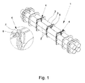
- Fig. 1 shows an embodiment of a Coriolis mass flowmeter 1 with four measuring tubes 2.
- vibration generator 3 and vibration sensor 4 are connected to the measuring tubes 2.
- both the vibration sensor 4 and the vibration generator 3 each comprise a permanent magnet 6 and a coil 7.
- vibrations can be transmitted to the measuring tubes 2 by means of electrical means or vibrations of the measuring tubes 2 can be detected.
- the vibration sensor 4 are attached to the inlet and outlet side of the measuring tube 2. Without flow, the signals of the two vibration sensor 4 are substantially in phase.
- the vibration behavior of the measuring tube 2 depends not only on the excitation of the measuring tube 2, but also of the measuring tube temperature, which affects the rigidity of the measuring tube, a possible structural change of the measuring tube 2, for example by corrosion, or by the temperature dependence
- the vibration behavior of the measuring tube 2 depends not only on the excitation of the measuring tube 2, but also of the measuring tube temperature, which affects the rigidity of the measuring tube, a possible structural change of the measuring tube 2, for example by corrosion, or by the temperature dependence
- there is a desire to compensate for such temperature effects be it in the determination of physical parameters of the Coriolis mass flowmeter, physical state variables or derived state variables D, which have no immediate physical meaning but are nevertheless suitable for determining the condition and thus also a change in the state of the Coriolis mass flowmeter.
- Fig. 2 shows a qualitative representation of the coil impedance R against the measuring tube temperature T at steady state conditions.
- the stationary case ie at a constant measuring tube temperature, there is a linear relationship between the coil impedance R and the measuring tube temperature T.
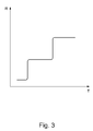
- FIG. 3 shows Fig. 3 a qualitative representation of the coil impedance R against the measuring tube temperature T at thermally unsteady conditions, ie at variable measuring tube temperature.
- a change in the measuring tube temperature T (horizontal) leads to a significantly delayed response of the coil impedance R.
- This delayed tracking leads to typical hysteresis effects both during a temperature increase and during cooling processes.
- the proposed method of operation of a Coriolis flowmeter counteracts this circumstance by correcting the temperature-dependent state variable D starting from the temperature of the measuring tube 2 with the specific impedance of the coil, since in the impedance of the coil 7 information about the temperature of the adjacent permanent magnet 6 is included.
- Fig. 4 shows the schematic sequence of an embodiment of the method described above.
- the vibration generator 3 attached to the Coriolis mass flowmeter 1 excites the measuring tubes 2 to vibrate in a first step 101.
- the vibrations are subsequently detected by the vibration sensors 4 in step 102.
- the temperature of the measuring tubes is determined in step 103.
- the electrical impedance of the coil is determined 104.
- the order of these steps is not on the in the Fig. 4 set order. Vibration detection, measuring tube temperature determination and the determination of the coil impedance can be carried out successively or simultaneously.
- the recorded signals are forwarded to an evaluation device 5.
- the evaluation device 5 calculates one or more state variables D of the Coriolis mass flowmeter 1 with the recorded signals. Since the preferred state variables which can provide information about the current state of the Coriolis mass flowmeter 1 are partly temperature-dependent, the measuring tube temperature is used for the determination of the actual temperature-dependent state value used.
- the resulting Meßrohrschwingungen are also dependent on the applied by the energization of the vibrator exciting force.
- the generated force is again dependent on the temperature of the permanent magnet 6, since its magnetization is temperature-dependent.
- the context of the in the Fig. 2 and Fig. 3 becomes clear to determine the magnet temperature or a value related to the magnet temperature or to the closer coil.
- the coil 7 has a known temperature coefficient.
- ⁇ T is the change in the measuring tube temperature
- ⁇ R drv the change in electrical impedance of the coil.
- the coefficients a 1 to a 3 represent empirical parameters for the Coriolis mass flowmeter.
- Fig. 5 shows an extension of the procedure.
- oscillations are generated in step 101 and then recorded 102.
- the measuring tube temperature T and the electrical coil impedance R are determined, so that the evaluation device 5 can calculate state variables from the determined values.
- a reference value D ref of the state variable D is determined before the start-up of the Coriolis mass flowmeter 1 in the installed situation.
- values D mess of the state variable D are continuously calculated from the recorded signals.
- the calculated values D mess are also continuously compared 108 with the previously determined reference value D ref .
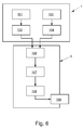
- Fig. 6 shows a further embodiment of the method for operating a Coriolis mass flowmeter 1.
- the operator of the Coriolis mass flowmeter 1 can recognize that the state of the measuring device has changed and, if necessary, take steps to restore the desired state.
Landscapes
- Physics & Mathematics (AREA)
- Fluid Mechanics (AREA)
- General Physics & Mathematics (AREA)
- Engineering & Computer Science (AREA)
- Signal Processing (AREA)
- Measuring Volume Flow (AREA)
Applications Claiming Priority (1)
| Application Number | Priority Date | Filing Date | Title |
|---|---|---|---|
| DE102015100573.5A DE102015100573A1 (de) | 2015-01-15 | 2015-01-15 | Verfahren zum Betreiben eines Coriolis-Massedurchflussmessgeräts |
Publications (2)
| Publication Number | Publication Date |
|---|---|
| EP3045877A1 true EP3045877A1 (fr) | 2016-07-20 |
| EP3045877B1 EP3045877B1 (fr) | 2018-09-26 |
Family
ID=54695625
Family Applications (1)
| Application Number | Title | Priority Date | Filing Date |
|---|---|---|---|
| EP15195810.5A Active EP3045877B1 (fr) | 2015-01-15 | 2015-11-23 | Procédé de fonctionnement d'un appareil de mesure de débit massique coriolis |
Country Status (4)
| Country | Link |
|---|---|
| US (1) | US9513150B2 (fr) |
| EP (1) | EP3045877B1 (fr) |
| CN (1) | CN105806432B (fr) |
| DE (1) | DE102015100573A1 (fr) |
Cited By (1)
| Publication number | Priority date | Publication date | Assignee | Title |
|---|---|---|---|---|
| US12276200B2 (en) | 2019-05-09 | 2025-04-15 | Mitsubishi Heavy Industries Engine & Turbocharger, Ltd. | Variable displacement exhaust turbocharger |
Families Citing this family (9)
| Publication number | Priority date | Publication date | Assignee | Title |
|---|---|---|---|---|
| DE102014105580A1 (de) * | 2014-04-17 | 2015-10-22 | Krohne Ag | Coriolis-Massedurchflussmessgerät |
| CN107764350B (zh) * | 2016-08-18 | 2020-05-08 | 高准有限公司 | 质量流量测量方法和质量流量计 |
| EP3548850B1 (fr) * | 2016-11-30 | 2021-03-31 | Micro Motion Inc. | Compensation de température d'une tonalité de test utilisée dans la vérification d'un appareil de mesure |
| DE102017102449A1 (de) * | 2017-02-08 | 2018-08-09 | Krohne Ag | Verfahren zur Druckmessung bei einem Coriolis-Massedurchflussmessgerät und Coriolis-Massedurchflussmessgerät |
| US12044550B2 (en) * | 2018-05-23 | 2024-07-23 | Iee International Electronics & Engineering S.A. | Method of compensating temperature influence in capacitive measurements |
| DE102019122094B3 (de) * | 2019-08-16 | 2021-01-28 | Endress+Hauser Flowtec Ag | Verfahren zur Berechnung einer Qualität eines Messrohrs eines Coriolis-Messgeräts und ein solches Messgerät |
| DE102019123344B3 (de) * | 2019-08-30 | 2021-02-25 | Endress+Hauser Flowtec Ag | Coriolis-Messaufnehmer und Coriolis-Messgerät mit einer Vorrichtung zur Bestimmung eines Alters von Magneten eines Sensors oder Erregers sowie ein Verfahren zur Altersbestimmung |
| DE102020130992A1 (de) * | 2020-11-24 | 2022-05-25 | Endress+Hauser Flowtec Ag | Verfahren zum Bestimmen eines Zustands eines Coriolis-Messgeräts |
| DE102022129037A1 (de) * | 2022-11-03 | 2024-05-08 | Krohne Messtechnik Gmbh | Verfahren zum Testen eines Coriolis-Massedurchflussmessgeräts |
Citations (7)
| Publication number | Priority date | Publication date | Assignee | Title |
|---|---|---|---|---|
| US5460049A (en) * | 1994-01-26 | 1995-10-24 | Instrumention Northwest, Inc. | Digitally-temperature-compensated strain-gauge pressure measuring apparatus |
| WO1998031990A1 (fr) * | 1997-01-16 | 1998-07-23 | Direct Measurement Corporation | Procedes de traitement de signaux et de verification sur place, et circuits pour debitmetre-masse a acceleration de coriolis |
| US20040221660A1 (en) * | 2003-05-05 | 2004-11-11 | Dutton Robert E. | Two-phase steam measurement system |
| DE102008059920A1 (de) | 2008-12-02 | 2010-07-01 | Krohne Meßtechnik GmbH & Co KG | Verfahren zum Betreiben eines Resonanzmeßsystems und diesbezügliches Resonanzmeßsystem |
| WO2012018323A1 (fr) * | 2010-08-02 | 2012-02-09 | Micro Motion, Inc. | Procédé et appareil servant à déterminer la température d'un composant capteur à vibration d'un dispositif de mesure à vibration |
| WO2012067608A1 (fr) * | 2010-11-16 | 2012-05-24 | Micro Motion, Inc. | Système de capteurs de température multiples |
| DE102012011934A1 (de) | 2012-06-18 | 2013-12-19 | Krohne Messtechnik Gmbh | Verfahren zum Betreiben eines Resonazmesssystems und diesbezügliche Resonanzmesssystem |
Family Cites Families (10)
| Publication number | Priority date | Publication date | Assignee | Title |
|---|---|---|---|---|
| US5231884A (en) * | 1991-07-11 | 1993-08-03 | Micro Motion, Inc. | Technique for substantially eliminating temperature induced measurement errors from a coriolis meter |
| DE4410160C1 (de) * | 1994-03-24 | 1995-10-05 | Ulrich Dipl Ing Elsen | Hochwärmebeständige Spule, insbesondere zur Verwendung als Antriebsspule und als Meßspule zum Antrieb und zum Messen der Schwingungen des Schwingrohres einer Vorrichtung zum Messen der Masse eines durch eine Rohrleitung fließenden Mediums |
| US5902931A (en) * | 1996-04-26 | 1999-05-11 | Murata Manufacturing Co., Ltd. | Vibration gyroscope |
| JP2002228453A (ja) * | 2001-01-31 | 2002-08-14 | Murata Mfg Co Ltd | 振動ジャイロおよびその温度ドリフト調整方法 |
| EP1724558A1 (fr) * | 2005-05-18 | 2006-11-22 | Endress + Hauser Flowtec AG | Appareils de mesure de débit/densité massique de type Coriolis et procédé pour compenser des erreurs de mesure dans de tels appareils |
| JP2008064544A (ja) * | 2006-09-06 | 2008-03-21 | Tokiko Techno Kk | 振動式測定装置 |
| US7801694B1 (en) * | 2007-09-27 | 2010-09-21 | Watson Industries, Inc. | Gyroscope with temperature compensation |
| JP5086814B2 (ja) * | 2008-01-07 | 2012-11-28 | 株式会社キーエンス | 流量計 |
| EP2861941B1 (fr) | 2012-06-18 | 2018-03-21 | KROHNE Messtechnik GmbH | Procédé d'opération d'un système de mesure à résonance |
| AU2014278632B2 (en) * | 2013-06-14 | 2016-10-20 | Micro Motion, Inc. | Vibratory flowmeter and method for meter verification |
-
2015
- 2015-01-15 DE DE102015100573.5A patent/DE102015100573A1/de not_active Withdrawn
- 2015-11-23 EP EP15195810.5A patent/EP3045877B1/fr active Active
- 2015-12-09 US US14/963,567 patent/US9513150B2/en active Active
- 2015-12-10 CN CN201510910132.2A patent/CN105806432B/zh active Active
Patent Citations (7)
| Publication number | Priority date | Publication date | Assignee | Title |
|---|---|---|---|---|
| US5460049A (en) * | 1994-01-26 | 1995-10-24 | Instrumention Northwest, Inc. | Digitally-temperature-compensated strain-gauge pressure measuring apparatus |
| WO1998031990A1 (fr) * | 1997-01-16 | 1998-07-23 | Direct Measurement Corporation | Procedes de traitement de signaux et de verification sur place, et circuits pour debitmetre-masse a acceleration de coriolis |
| US20040221660A1 (en) * | 2003-05-05 | 2004-11-11 | Dutton Robert E. | Two-phase steam measurement system |
| DE102008059920A1 (de) | 2008-12-02 | 2010-07-01 | Krohne Meßtechnik GmbH & Co KG | Verfahren zum Betreiben eines Resonanzmeßsystems und diesbezügliches Resonanzmeßsystem |
| WO2012018323A1 (fr) * | 2010-08-02 | 2012-02-09 | Micro Motion, Inc. | Procédé et appareil servant à déterminer la température d'un composant capteur à vibration d'un dispositif de mesure à vibration |
| WO2012067608A1 (fr) * | 2010-11-16 | 2012-05-24 | Micro Motion, Inc. | Système de capteurs de température multiples |
| DE102012011934A1 (de) | 2012-06-18 | 2013-12-19 | Krohne Messtechnik Gmbh | Verfahren zum Betreiben eines Resonazmesssystems und diesbezügliche Resonanzmesssystem |
Cited By (1)
| Publication number | Priority date | Publication date | Assignee | Title |
|---|---|---|---|---|
| US12276200B2 (en) | 2019-05-09 | 2025-04-15 | Mitsubishi Heavy Industries Engine & Turbocharger, Ltd. | Variable displacement exhaust turbocharger |
Also Published As
| Publication number | Publication date |
|---|---|
| US9513150B2 (en) | 2016-12-06 |
| US20160209257A1 (en) | 2016-07-21 |
| CN105806432A (zh) | 2016-07-27 |
| EP3045877B1 (fr) | 2018-09-26 |
| CN105806432B (zh) | 2019-09-27 |
| DE102015100573A1 (de) | 2016-07-21 |
Similar Documents
| Publication | Publication Date | Title |
|---|---|---|
| EP3045877B1 (fr) | Procédé de fonctionnement d'un appareil de mesure de débit massique coriolis | |
| EP2196780B1 (fr) | Procédé d'opération d'un système de mesure à résonance et système de mesure à résonance | |
| DE10002635C2 (de) | Verfahren zur Bestimmung wenigstens einer charakteristischen Größe eines Massendurchflußmeßgeräts | |
| EP2677284B1 (fr) | Procédé de fonctionnement d'un système de mesure à résonance et système de mesure à résonance correspondant | |
| EP2614337B1 (fr) | Procédé de détection d'un engorgement dans un débitmètre à effet coriolis | |
| EP2884244B1 (fr) | Procédé de fonctionnement d'un débitmètre massique Coriolis | |
| EP3256822B1 (fr) | Dispositif pour déterminer et/ou surveiller au moins une grandeur de processus d'un milieu et procédé correspondant | |
| DE102012017797A1 (de) | Durchflussmessgerät | |
| DE102016125537A1 (de) | Massedurchflussmessaufnehmer nach dem Coriolis-Prinzip und Verfahren zum Bestimmen eines Massedurchflusses | |
| EP2702370B1 (fr) | Procédé pour faire fonctionner un système de mesure par résonance | |
| DE102019123368A1 (de) | Verfahren und Messgerät zum Bestimmen der Viskosität eines Mediums | |
| EP3196605B1 (fr) | Procédé d'opération d'un débitmètre massique du type coriolis et débitmètre massique du type coriolis | |
| EP4251969B1 (fr) | Procédé et dispositif de mesure pour déterminer une valeur de mesure de viscosité, et procédé et ensemble de mesure pour déterminer une valeur de mesure de débit | |
| EP3628983B1 (fr) | Procédé de détermination de la teneur en gaz dans un milieu traversant un appareil de mesure de débit massique du type coriolis et appareil de mesure de débit massique du type coriolis | |
| EP3208598B1 (fr) | Procédé de fonctionnement d'un appareil de mesure de débit massique coriolis | |
| WO2008152060A1 (fr) | Procédé pour mesurer et/ou surveiller un paramètre d'écoulement et dispositif correspondant | |
| EP3361222B1 (fr) | Procédé de mesure de pression dans un débitmètre massique à accélération de coriolis et débitmètre massique à accélération de coriolis | |
| EP3196603B1 (fr) | Procédé de fonctionnement d'un débitmètre massique à accélération de coriolis et débitmètre massique à accélération de coriolis correspondant | |
| EP3196604B1 (fr) | Procédé de fonctionnement d'un débitmètre massique à accélération de coriolis et débitmètre massique à accélération de coriolis correspondant | |
| EP4014013B1 (fr) | Procédé de calcul d'une qualité d'un tube de mesure d'un dispositif de mesure de coriolis, et dispositif de mesure associé | |
| DE102017006710A1 (de) | Verfahren zur Korrektur eines Messwerts des Massenstroms eines Fluids durch ein Coriolis-Massendurchflussgerät und Coriolis-Massendurchflussmessgerät | |
| EP1711391B1 (fr) | Procede et dispositif pour determiner une valeur moyenne temporelle d'un courant a modulation d'impulsions en largeur d'un moteur electrique | |
| DE102007024276A1 (de) | Verfahren zur Messung und/oder Überwachung eines Strömungsparameters und entsprechende Vorrichtung | |
| DE102010040895A1 (de) | Verfahren und Vorrichtung zur Messung von Fluidströmen | |
| DE102005051793A1 (de) | Verfahren zur Bestimmung einer Prozessgröße eines Mediums |
Legal Events
| Date | Code | Title | Description |
|---|---|---|---|
| PUAI | Public reference made under article 153(3) epc to a published international application that has entered the european phase |
Free format text: ORIGINAL CODE: 0009012 |
|
| AK | Designated contracting states |
Kind code of ref document: A1 Designated state(s): AL AT BE BG CH CY CZ DE DK EE ES FI FR GB GR HR HU IE IS IT LI LT LU LV MC MK MT NL NO PL PT RO RS SE SI SK SM TR |
|
| AX | Request for extension of the european patent |
Extension state: BA ME |
|
| 17P | Request for examination filed |
Effective date: 20160908 |
|
| RBV | Designated contracting states (corrected) |
Designated state(s): AL AT BE BG CH CY CZ DE DK EE ES FI FR GB GR HR HU IE IS IT LI LT LU LV MC MK MT NL NO PL PT RO RS SE SI SK SM TR |
|
| STAA | Information on the status of an ep patent application or granted ep patent |
Free format text: STATUS: EXAMINATION IS IN PROGRESS |
|
| 17Q | First examination report despatched |
Effective date: 20170516 |
|
| GRAP | Despatch of communication of intention to grant a patent |
Free format text: ORIGINAL CODE: EPIDOSNIGR1 |
|
| STAA | Information on the status of an ep patent application or granted ep patent |
Free format text: STATUS: GRANT OF PATENT IS INTENDED |
|
| GRAS | Grant fee paid |
Free format text: ORIGINAL CODE: EPIDOSNIGR3 |
|
| INTG | Intention to grant announced |
Effective date: 20180515 |
|
| GRAA | (expected) grant |
Free format text: ORIGINAL CODE: 0009210 |
|
| STAA | Information on the status of an ep patent application or granted ep patent |
Free format text: STATUS: THE PATENT HAS BEEN GRANTED |
|
| AK | Designated contracting states |
Kind code of ref document: B1 Designated state(s): AL AT BE BG CH CY CZ DE DK EE ES FI FR GB GR HR HU IE IS IT LI LT LU LV MC MK MT NL NO PL PT RO RS SE SI SK SM TR |
|
| REG | Reference to a national code |
Ref country code: GB Ref legal event code: FG4D Free format text: NOT ENGLISH |
|
| REG | Reference to a national code |
Ref country code: CH Ref legal event code: EP |
|
| REG | Reference to a national code |
Ref country code: AT Ref legal event code: REF Ref document number: 1046565 Country of ref document: AT Kind code of ref document: T Effective date: 20181015 |
|
| REG | Reference to a national code |
Ref country code: IE Ref legal event code: FG4D Free format text: LANGUAGE OF EP DOCUMENT: GERMAN |
|
| REG | Reference to a national code |
Ref country code: DE Ref legal event code: R096 Ref document number: 502015006060 Country of ref document: DE |
|
| REG | Reference to a national code |
Ref country code: NL Ref legal event code: MP Effective date: 20180926 |
|
| PG25 | Lapsed in a contracting state [announced via postgrant information from national office to epo] |
Ref country code: NO Free format text: LAPSE BECAUSE OF FAILURE TO SUBMIT A TRANSLATION OF THE DESCRIPTION OR TO PAY THE FEE WITHIN THE PRESCRIBED TIME-LIMIT Effective date: 20181226 Ref country code: GR Free format text: LAPSE BECAUSE OF FAILURE TO SUBMIT A TRANSLATION OF THE DESCRIPTION OR TO PAY THE FEE WITHIN THE PRESCRIBED TIME-LIMIT Effective date: 20181227 Ref country code: BG Free format text: LAPSE BECAUSE OF FAILURE TO SUBMIT A TRANSLATION OF THE DESCRIPTION OR TO PAY THE FEE WITHIN THE PRESCRIBED TIME-LIMIT Effective date: 20181226 Ref country code: SE Free format text: LAPSE BECAUSE OF FAILURE TO SUBMIT A TRANSLATION OF THE DESCRIPTION OR TO PAY THE FEE WITHIN THE PRESCRIBED TIME-LIMIT Effective date: 20180926 Ref country code: LT Free format text: LAPSE BECAUSE OF FAILURE TO SUBMIT A TRANSLATION OF THE DESCRIPTION OR TO PAY THE FEE WITHIN THE PRESCRIBED TIME-LIMIT Effective date: 20180926 Ref country code: RS Free format text: LAPSE BECAUSE OF FAILURE TO SUBMIT A TRANSLATION OF THE DESCRIPTION OR TO PAY THE FEE WITHIN THE PRESCRIBED TIME-LIMIT Effective date: 20180926 Ref country code: FI Free format text: LAPSE BECAUSE OF FAILURE TO SUBMIT A TRANSLATION OF THE DESCRIPTION OR TO PAY THE FEE WITHIN THE PRESCRIBED TIME-LIMIT Effective date: 20180926 |
|
| REG | Reference to a national code |
Ref country code: LT Ref legal event code: MG4D |
|
| PG25 | Lapsed in a contracting state [announced via postgrant information from national office to epo] |
Ref country code: AL Free format text: LAPSE BECAUSE OF FAILURE TO SUBMIT A TRANSLATION OF THE DESCRIPTION OR TO PAY THE FEE WITHIN THE PRESCRIBED TIME-LIMIT Effective date: 20180926 Ref country code: HR Free format text: LAPSE BECAUSE OF FAILURE TO SUBMIT A TRANSLATION OF THE DESCRIPTION OR TO PAY THE FEE WITHIN THE PRESCRIBED TIME-LIMIT Effective date: 20180926 Ref country code: LV Free format text: LAPSE BECAUSE OF FAILURE TO SUBMIT A TRANSLATION OF THE DESCRIPTION OR TO PAY THE FEE WITHIN THE PRESCRIBED TIME-LIMIT Effective date: 20180926 |
|
| PG25 | Lapsed in a contracting state [announced via postgrant information from national office to epo] |
Ref country code: EE Free format text: LAPSE BECAUSE OF FAILURE TO SUBMIT A TRANSLATION OF THE DESCRIPTION OR TO PAY THE FEE WITHIN THE PRESCRIBED TIME-LIMIT Effective date: 20180926 Ref country code: IT Free format text: LAPSE BECAUSE OF FAILURE TO SUBMIT A TRANSLATION OF THE DESCRIPTION OR TO PAY THE FEE WITHIN THE PRESCRIBED TIME-LIMIT Effective date: 20180926 Ref country code: NL Free format text: LAPSE BECAUSE OF FAILURE TO SUBMIT A TRANSLATION OF THE DESCRIPTION OR TO PAY THE FEE WITHIN THE PRESCRIBED TIME-LIMIT Effective date: 20180926 Ref country code: RO Free format text: LAPSE BECAUSE OF FAILURE TO SUBMIT A TRANSLATION OF THE DESCRIPTION OR TO PAY THE FEE WITHIN THE PRESCRIBED TIME-LIMIT Effective date: 20180926 Ref country code: IS Free format text: LAPSE BECAUSE OF FAILURE TO SUBMIT A TRANSLATION OF THE DESCRIPTION OR TO PAY THE FEE WITHIN THE PRESCRIBED TIME-LIMIT Effective date: 20190126 Ref country code: CZ Free format text: LAPSE BECAUSE OF FAILURE TO SUBMIT A TRANSLATION OF THE DESCRIPTION OR TO PAY THE FEE WITHIN THE PRESCRIBED TIME-LIMIT Effective date: 20180926 Ref country code: PL Free format text: LAPSE BECAUSE OF FAILURE TO SUBMIT A TRANSLATION OF THE DESCRIPTION OR TO PAY THE FEE WITHIN THE PRESCRIBED TIME-LIMIT Effective date: 20180926 Ref country code: ES Free format text: LAPSE BECAUSE OF FAILURE TO SUBMIT A TRANSLATION OF THE DESCRIPTION OR TO PAY THE FEE WITHIN THE PRESCRIBED TIME-LIMIT Effective date: 20180926 |
|
| PG25 | Lapsed in a contracting state [announced via postgrant information from national office to epo] |
Ref country code: SK Free format text: LAPSE BECAUSE OF FAILURE TO SUBMIT A TRANSLATION OF THE DESCRIPTION OR TO PAY THE FEE WITHIN THE PRESCRIBED TIME-LIMIT Effective date: 20180926 Ref country code: PT Free format text: LAPSE BECAUSE OF FAILURE TO SUBMIT A TRANSLATION OF THE DESCRIPTION OR TO PAY THE FEE WITHIN THE PRESCRIBED TIME-LIMIT Effective date: 20190126 Ref country code: SM Free format text: LAPSE BECAUSE OF FAILURE TO SUBMIT A TRANSLATION OF THE DESCRIPTION OR TO PAY THE FEE WITHIN THE PRESCRIBED TIME-LIMIT Effective date: 20180926 |
|
| REG | Reference to a national code |
Ref country code: DE Ref legal event code: R097 Ref document number: 502015006060 Country of ref document: DE |
|
| PG25 | Lapsed in a contracting state [announced via postgrant information from national office to epo] |
Ref country code: MC Free format text: LAPSE BECAUSE OF FAILURE TO SUBMIT A TRANSLATION OF THE DESCRIPTION OR TO PAY THE FEE WITHIN THE PRESCRIBED TIME-LIMIT Effective date: 20180926 Ref country code: DK Free format text: LAPSE BECAUSE OF FAILURE TO SUBMIT A TRANSLATION OF THE DESCRIPTION OR TO PAY THE FEE WITHIN THE PRESCRIBED TIME-LIMIT Effective date: 20180926 Ref country code: LU Free format text: LAPSE BECAUSE OF NON-PAYMENT OF DUE FEES Effective date: 20181123 |
|
| PLBE | No opposition filed within time limit |
Free format text: ORIGINAL CODE: 0009261 |
|
| STAA | Information on the status of an ep patent application or granted ep patent |
Free format text: STATUS: NO OPPOSITION FILED WITHIN TIME LIMIT |
|
| REG | Reference to a national code |
Ref country code: BE Ref legal event code: MM Effective date: 20181130 |
|
| REG | Reference to a national code |
Ref country code: IE Ref legal event code: MM4A |
|
| 26N | No opposition filed |
Effective date: 20190627 |
|
| PG25 | Lapsed in a contracting state [announced via postgrant information from national office to epo] |
Ref country code: SI Free format text: LAPSE BECAUSE OF FAILURE TO SUBMIT A TRANSLATION OF THE DESCRIPTION OR TO PAY THE FEE WITHIN THE PRESCRIBED TIME-LIMIT Effective date: 20180926 Ref country code: IE Free format text: LAPSE BECAUSE OF NON-PAYMENT OF DUE FEES Effective date: 20181123 |
|
| PG25 | Lapsed in a contracting state [announced via postgrant information from national office to epo] |
Ref country code: BE Free format text: LAPSE BECAUSE OF NON-PAYMENT OF DUE FEES Effective date: 20181130 |
|
| PG25 | Lapsed in a contracting state [announced via postgrant information from national office to epo] |
Ref country code: MT Free format text: LAPSE BECAUSE OF FAILURE TO SUBMIT A TRANSLATION OF THE DESCRIPTION OR TO PAY THE FEE WITHIN THE PRESCRIBED TIME-LIMIT Effective date: 20180926 |
|
| PG25 | Lapsed in a contracting state [announced via postgrant information from national office to epo] |
Ref country code: TR Free format text: LAPSE BECAUSE OF FAILURE TO SUBMIT A TRANSLATION OF THE DESCRIPTION OR TO PAY THE FEE WITHIN THE PRESCRIBED TIME-LIMIT Effective date: 20180926 |
|
| PG25 | Lapsed in a contracting state [announced via postgrant information from national office to epo] |
Ref country code: HU Free format text: LAPSE BECAUSE OF FAILURE TO SUBMIT A TRANSLATION OF THE DESCRIPTION OR TO PAY THE FEE WITHIN THE PRESCRIBED TIME-LIMIT; INVALID AB INITIO Effective date: 20151123 Ref country code: CY Free format text: LAPSE BECAUSE OF FAILURE TO SUBMIT A TRANSLATION OF THE DESCRIPTION OR TO PAY THE FEE WITHIN THE PRESCRIBED TIME-LIMIT Effective date: 20180926 Ref country code: MK Free format text: LAPSE BECAUSE OF NON-PAYMENT OF DUE FEES Effective date: 20180926 |
|
| REG | Reference to a national code |
Ref country code: AT Ref legal event code: MM01 Ref document number: 1046565 Country of ref document: AT Kind code of ref document: T Effective date: 20201123 |
|
| PG25 | Lapsed in a contracting state [announced via postgrant information from national office to epo] |
Ref country code: AT Free format text: LAPSE BECAUSE OF NON-PAYMENT OF DUE FEES Effective date: 20201123 |
|
| P01 | Opt-out of the competence of the unified patent court (upc) registered |
Effective date: 20230607 |
|
| REG | Reference to a national code |
Ref country code: CH Ref legal event code: U11 Free format text: ST27 STATUS EVENT CODE: U-0-0-U10-U11 (AS PROVIDED BY THE NATIONAL OFFICE) Effective date: 20251201 |
|
| PGFP | Annual fee paid to national office [announced via postgrant information from national office to epo] |
Ref country code: GB Payment date: 20251121 Year of fee payment: 11 |
|
| PGFP | Annual fee paid to national office [announced via postgrant information from national office to epo] |
Ref country code: FR Payment date: 20251125 Year of fee payment: 11 |
|
| PGFP | Annual fee paid to national office [announced via postgrant information from national office to epo] |
Ref country code: CH Payment date: 20251201 Year of fee payment: 11 |
|
| PGFP | Annual fee paid to national office [announced via postgrant information from national office to epo] |
Ref country code: DE Payment date: 20260112 Year of fee payment: 11 |