EP3045887B1 - Procédé pour la détection d'un défaut, système de détection de défaut et moteur de turbine à gaz - Google Patents
Procédé pour la détection d'un défaut, système de détection de défaut et moteur de turbine à gaz Download PDFInfo
- Publication number
- EP3045887B1 EP3045887B1 EP15201517.8A EP15201517A EP3045887B1 EP 3045887 B1 EP3045887 B1 EP 3045887B1 EP 15201517 A EP15201517 A EP 15201517A EP 3045887 B1 EP3045887 B1 EP 3045887B1
- Authority
- EP
- European Patent Office
- Prior art keywords
- pressure difference
- ducts
- open
- gas
- modulated
- Prior art date
- Legal status (The legal status is an assumption and is not a legal conclusion. Google has not performed a legal analysis and makes no representation as to the accuracy of the status listed.)
- Not-in-force
Links
- 238000001514 detection method Methods 0.000 title claims description 28
- 238000000034 method Methods 0.000 title claims description 24
- 238000005259 measurement Methods 0.000 description 12
- 239000000446 fuel Substances 0.000 description 6
- 238000012423 maintenance Methods 0.000 description 6
- 238000002485 combustion reaction Methods 0.000 description 4
- 238000010276 construction Methods 0.000 description 4
- 238000010079 rubber tapping Methods 0.000 description 4
- 230000008901 benefit Effects 0.000 description 3
- 238000001816 cooling Methods 0.000 description 3
- 230000009471 action Effects 0.000 description 2
- 238000012544 monitoring process Methods 0.000 description 2
- 230000001141 propulsive effect Effects 0.000 description 2
- 238000013459 approach Methods 0.000 description 1
- 230000009172 bursting Effects 0.000 description 1
- 230000008859 change Effects 0.000 description 1
- 230000006835 compression Effects 0.000 description 1
- 238000007906 compression Methods 0.000 description 1
- 235000009508 confectionery Nutrition 0.000 description 1
- 230000001276 controlling effect Effects 0.000 description 1
- 230000010006 flight Effects 0.000 description 1
- 231100001261 hazardous Toxicity 0.000 description 1
- 238000002347 injection Methods 0.000 description 1
- 239000007924 injection Substances 0.000 description 1
- 230000033001 locomotion Effects 0.000 description 1
- 239000000203 mixture Substances 0.000 description 1
- 238000012986 modification Methods 0.000 description 1
- 230000004048 modification Effects 0.000 description 1
- 230000009467 reduction Effects 0.000 description 1
- 230000001105 regulatory effect Effects 0.000 description 1
- 230000004044 response Effects 0.000 description 1
- 238000005070 sampling Methods 0.000 description 1
- 230000035945 sensitivity Effects 0.000 description 1
- 238000011179 visual inspection Methods 0.000 description 1
Images

Classifications
-
- F—MECHANICAL ENGINEERING; LIGHTING; HEATING; WEAPONS; BLASTING
- F02—COMBUSTION ENGINES; HOT-GAS OR COMBUSTION-PRODUCT ENGINE PLANTS
- F02C—GAS-TURBINE PLANTS; AIR INTAKES FOR JET-PROPULSION PLANTS; CONTROLLING FUEL SUPPLY IN AIR-BREATHING JET-PROPULSION PLANTS
- F02C6/00—Plural gas-turbine plants; Combinations of gas-turbine plants with other apparatus; Adaptations of gas-turbine plants for special use
- F02C6/04—Gas-turbine plants providing heated or pressurised working fluid for other apparatus, e.g. without mechanical power output
- F02C6/06—Gas-turbine plants providing heated or pressurised working fluid for other apparatus, e.g. without mechanical power output providing compressed gas
- F02C6/08—Gas-turbine plants providing heated or pressurised working fluid for other apparatus, e.g. without mechanical power output providing compressed gas the gas being bled from the gas-turbine compressor
-
- F—MECHANICAL ENGINEERING; LIGHTING; HEATING; WEAPONS; BLASTING
- F02—COMBUSTION ENGINES; HOT-GAS OR COMBUSTION-PRODUCT ENGINE PLANTS
- F02C—GAS-TURBINE PLANTS; AIR INTAKES FOR JET-PROPULSION PLANTS; CONTROLLING FUEL SUPPLY IN AIR-BREATHING JET-PROPULSION PLANTS
- F02C9/00—Controlling gas-turbine plants; Controlling fuel supply in air- breathing jet-propulsion plants
-
- G—PHYSICS
- G01—MEASURING; TESTING
- G01M—TESTING STATIC OR DYNAMIC BALANCE OF MACHINES OR STRUCTURES; TESTING OF STRUCTURES OR APPARATUS, NOT OTHERWISE PROVIDED FOR
- G01M15/00—Testing of engines
- G01M15/14—Testing gas-turbine engines or jet-propulsion engines
-
- G—PHYSICS
- G01—MEASURING; TESTING
- G01M—TESTING STATIC OR DYNAMIC BALANCE OF MACHINES OR STRUCTURES; TESTING OF STRUCTURES OR APPARATUS, NOT OTHERWISE PROVIDED FOR
- G01M3/00—Investigating fluid-tightness of structures
- G01M3/02—Investigating fluid-tightness of structures by using fluid or vacuum
- G01M3/26—Investigating fluid-tightness of structures by using fluid or vacuum by measuring rate of loss or gain of fluid, e.g. by pressure-responsive devices, by flow detectors
- G01M3/28—Investigating fluid-tightness of structures by using fluid or vacuum by measuring rate of loss or gain of fluid, e.g. by pressure-responsive devices, by flow detectors for pipes, cables or tubes; for pipe joints or seals; for valves ; for welds
- G01M3/2807—Investigating fluid-tightness of structures by using fluid or vacuum by measuring rate of loss or gain of fluid, e.g. by pressure-responsive devices, by flow detectors for pipes, cables or tubes; for pipe joints or seals; for valves ; for welds for pipes
- G01M3/2815—Investigating fluid-tightness of structures by using fluid or vacuum by measuring rate of loss or gain of fluid, e.g. by pressure-responsive devices, by flow detectors for pipes, cables or tubes; for pipe joints or seals; for valves ; for welds for pipes using pressure measurements
-
- G—PHYSICS
- G01—MEASURING; TESTING
- G01M—TESTING STATIC OR DYNAMIC BALANCE OF MACHINES OR STRUCTURES; TESTING OF STRUCTURES OR APPARATUS, NOT OTHERWISE PROVIDED FOR
- G01M3/00—Investigating fluid-tightness of structures
- G01M3/02—Investigating fluid-tightness of structures by using fluid or vacuum
- G01M3/26—Investigating fluid-tightness of structures by using fluid or vacuum by measuring rate of loss or gain of fluid, e.g. by pressure-responsive devices, by flow detectors
- G01M3/28—Investigating fluid-tightness of structures by using fluid or vacuum by measuring rate of loss or gain of fluid, e.g. by pressure-responsive devices, by flow detectors for pipes, cables or tubes; for pipe joints or seals; for valves ; for welds
- G01M3/2876—Investigating fluid-tightness of structures by using fluid or vacuum by measuring rate of loss or gain of fluid, e.g. by pressure-responsive devices, by flow detectors for pipes, cables or tubes; for pipe joints or seals; for valves ; for welds for valves
-
- F—MECHANICAL ENGINEERING; LIGHTING; HEATING; WEAPONS; BLASTING
- F05—INDEXING SCHEMES RELATING TO ENGINES OR PUMPS IN VARIOUS SUBCLASSES OF CLASSES F01-F04
- F05D—INDEXING SCHEME FOR ASPECTS RELATING TO NON-POSITIVE-DISPLACEMENT MACHINES OR ENGINES, GAS-TURBINES OR JET-PROPULSION PLANTS
- F05D2260/00—Function
- F05D2260/80—Diagnostics
-
- F—MECHANICAL ENGINEERING; LIGHTING; HEATING; WEAPONS; BLASTING
- F05—INDEXING SCHEMES RELATING TO ENGINES OR PUMPS IN VARIOUS SUBCLASSES OF CLASSES F01-F04
- F05D—INDEXING SCHEME FOR ASPECTS RELATING TO NON-POSITIVE-DISPLACEMENT MACHINES OR ENGINES, GAS-TURBINES OR JET-PROPULSION PLANTS
- F05D2270/00—Control
- F05D2270/30—Control parameters, e.g. input parameters
- F05D2270/301—Pressure
- F05D2270/3015—Pressure differential pressure
Definitions
- the present disclosure relates to a method for detecting a fault in a gas supply system for a gas turbine engine.
- the present disclosure also relates to a fault detection system for detecting a fault in a gas supply system for a gas turbine engine, and to a gas turbine engine comprising the fault detection system.
- Gas turbine engines may include a number of ducts (sometimes called pipes) which carry high pressure air from a compressor to the turbine.
- the ducts may carry the high pressure air externally to the engine casings.
- the air may be used to cool the turbine components and/or to control the movement of oil within bearings.
- ducts may be used to supply air for other purposes such as a cabin air system and bleed valves.
- Ducts may contain flow controllers to switch them from high flow to no-flow or a low flow condition.
- the gas supply system comprising the ducts may be designed to provide enough flow at high power/low altitude conditions (e.g. during take off). This flow is enough to over supply the turbine during cruise conditions. By reducing the flow in cruise conditions, fuel can be saved.
- the nacelle and/or components within the turbine zone may be overheated.
- FR2976225 relates to a method of controlling an air sampling system including measuring a pressure difference between an intermediate pressure air inlet valve and an inlet of an air pressure regulating valve. The method may also include comparing the pressure difference to a threshold value and closing the intermediate pressure air inlet valve or a high pressure air inlet valve when required in response to this comparison.
- US6799112 relates to a method of detecting airflow reversal in a sump system of a gas turbine engine.
- WO2009/094734 relates to an air bleed balancing control system for a pair of aircraft gas turbine engines.
- a method for detecting a fault in a gas turbine supply system according to claim 1. If the measured pressure difference goes above a set level (i.e. the threshold level), then a fault such as a burst gas supplying duct may be indicated. Accordingly, it is possible to detect more easily and quickly whether urgent maintenance action is required. This can help prevent damage being caused to components in the region of the turbine, or to the nacelle itself.
- a set level i.e. the threshold level
- the invention may be quicker, easier and more reliable to detect a failure in the gas supply system within a single flight. This reduces the possibility of damage to components of the aircraft resulting from bursting of the gas supply system.
- urgent maintenance can be carried out at an earlier stage because the fault has been detected at an earlier stage. Detection of failures of the gas supply system can be used to optimise the system. For example, maintenance may be directed to restore the fuel burn benefit of the gas supply system if the failure is in the high flow condition (e.g. if a flow controller of the gas supply system is locked in a high flow condition) or to increase safety by limiting the extent of a failure leading to a reduction in flow.
- the pressure in the open-type duct is greater than the pressure in the modulated-type duct and the measured pressure difference is greater than the threshold level, it may be determined that the modulated -type duct is burst.
- the measuring may be performed when the flow controller is commanded to be in the high flow condition.
- the method may comprise commanding the flow controller to switch to the low flow condition, re-measuring a pressure difference between the two gas supplying ducts and comparing the re-measured pressure difference to the measured pressure difference.
- the flow controller is locked in the high flow condition.
- the open-type duct is burst.
- the measured pressure difference is greater than the threshold level and the re-measured pressure difference is substantially the same as the measured pressure difference, it may be determined that the flow controller is locked in the low flow condition.
- the threshold level may differ depending on whether or not the pressure in the open-type duct is greater than the pressure in the modulated-type duct.
- Two gas supplying ducts may be open-type ducts configured to remain open for gas supply through the open-type duct. When a measured pressure difference is greater than a threshold level, it may be determined that the open-type duct in which the pressure is lower is burst.
- the threshold level may be calculated based on a current engine condition of the gas turbine engine and/or altitude of the gas turbine engine.
- a fault detection system for detecting a fault in a gas supply system for a gas turbine engine may comprise: a differential pressure sensor for measuring a pressure difference between two gas supplying ducts of the gas supply system; a comparison unit for comparing the measured pressure difference to a threshold level; and a determination unit for determining a fault based on the measured pressure difference and the comparison.
- the gas supply system may comprise a plurality of modulated-type ducts and a corresponding plurality of open-type ducts.
- the fault detection system may comprise a corresponding plurality of differential pressure sensors, each for measuring a pressure difference between one of the modulated-type ducts and a corresponding one of the open-type ducts.
- the comparison unit may be for comparing, for each differential pressure sensor, the measured pressure difference to the threshold level.
- the determination unit may be for determining, for each measured pressure difference and comparison, a fault based on the measured pressure difference and the comparison.
- the gas supply system may comprise a plurality of modulated-type ducts.
- the fault detection system may comprise a corresponding plurality of differential pressure sensors, each for measuring a pressure difference between the open-type duct and one of the modulated-type ducts.
- the comparison unit may be for comparing, for each differential pressure sensor, the measured pressure difference to the threshold level.
- the determination unit may be for determining, for each measured pressure difference and comparison, a fault based on the measured pressure difference and the comparison.
- a ducted fan gas turbine engine generally indicated at 10 has a principal and rotational axis X-X.
- the engine 10 comprises, in axial flow series, an air intake 11, a compressive fan 12 (which may also be referred to as a low pressure compressor), an intermediate pressure compressor 13, a high-pressure compressor 14, combustion equipment 15, a high-pressure turbine 16, an intermediate pressure turbine 17, a low-pressure turbine 18 and a core exhaust nozzle 19.
- the engine also has a bypass duct 22 and a bypass exhaust nozzle 23.
- the gas turbine engine 10 works in a conventional manner so that the air entering the intake 11 is accelerated by the fan 12 to produce two air flows; a first air flow C into the intermediate pressure compressor 13 and a second air flow D which passes through the bypass duct 22 to provide propulsive thrust.
- the intermediate pressure compressor 13 compresses the air flow C directed into it before delivering that air to the high pressure compressor 14 where further compression takes place.
- the compressed air exhausted from the high-pressure compressor 14 is directed into the combustion equipment 15 where it is mixed with fuel and the mixture combusted.
- the resulting hot combustion products then expand through, and thereby drive the high, intermediate and low-pressure turbines 16, 17 and 18 before being exhausted through the nozzle 19 to provide additional propulsive thrust.
- the high, intermediate and low-pressure turbines 16, 17, 18 respectively drive the high and intermediate pressure compressors, 14, 13 and the fan 12 by suitable interconnecting shafts.
- Figure 2 shows a possible fault detection system for detecting a fault in a gas supply system 5 for a gas turbine engine 10.
- the gas supplying system 5 supplies gas from a gas supplying component 6 to a gas receiving component 7.
- the gas supplying component may be a compressor source.
- the gas supplying component may be one of the compressive fan 12, the intermediate pressure compressor 13 and the high-pressure compressor 14 shown in Figure 1 .
- the gas supplying component 6 may be an alternative compressor source.
- the gas receiving component 7 may be an internal manifold of a turbine.
- the gas receiving component 7 may be one of the high-pressure turbine 16, the intermediate pressure turbine 17 and the low-pressure turbine 18 shown in Figure 1 .
- the gas receiving component may be an alternative system such as a cabin air supply system or bleed valves.
- Blades of the turbines 16, 17, 18 can be cooled by extracting air from the high-pressure compressor 14. Air can be bled from the high-pressure compressor 14, routed around the combustion equipment 15 and put into the turbines 16, 17, 18. Cooling the blades in this way can increase the fuel consumption of the gas turbine engine.
- the fault detection system may comprise a differential pressure sensor 25.
- the differential pressure sensor 25 is for measuring a pressure difference ⁇ P between two gas supplying ducts A of the gas supply system 5.
- the differential pressure sensor 25 may determine which gas supplying duct A has the higher pressure.
- the differential pressure sensor 25 may measure the magnitude of the pressure difference ⁇ P between the two gas supplying ducts A.
- Figure 2 shows that the gas supplying system 5 may comprise six gas supplying ducts A.
- the number of gas supplying ducts is not particularly limited.
- the number of gas supplying ducts in the gas supplying system 5 may be two, three, four, five or more than six.
- the differential pressure sensor 25 is for measuring the pressure difference ⁇ P between the two gas supplying ducts A shown at the bottom of the gas supply system 5 as viewed in Figure 2 .
- the type of sensor used for the differential pressure sensor 25 is not particularly limited.
- the pressure difference ⁇ P may be measured by the differential pressure sensor in any suitable manner.
- pressure tappings may be introduced into the gas supplying ducts A.
- the pressure may be led to a differential pressure transducer using tubes.
- the differential pressure sensor 25 may comprise two pressure tappings connected to two corresponding tubes leading to a differential pressure transducer.
- a method for detecting a fault in the gas supply system 5 may comprise measuring the pressure difference ⁇ P between the two gas supplying ducts A of the gas supply system 5.
- the pressure difference ⁇ P may be measured using the differential pressure sensor 25.
- the method for detecting a fault may further comprise comparing the measured pressure difference ⁇ P to a threshold level.
- failures can be detected by looking for unusual values of the pressure difference ⁇ P.
- faults that can be detected include one of the gas supplying ducts A being burst.
- the gas supplying system is operating normally (i.e. without any faults)
- only small values for the pressure difference ⁇ P may be expected.
- a fault such as a burst gas supplying duct may be indicated. Accordingly, it is possible to detect more easily and quickly whether urgent maintenance action is required. This can help prevent damage being caused to components in the region of the turbine, or to the nacelle itself.
- each of the two gas supplying ducts A connected to the differential pressure sensor 25 is an open-type duct A.
- An open-type duct A is a gas supplying duct A configured to remain open for gas supply through the open-type duct A.
- the open-type duct A is not switched between a high flow condition and a low flow condition. Instead, the open-type duct A is always in the high flow condition. It may be that in an open-type duct, the gas supply through the open-type duct A cannot be stopped.
- an open-type duct A does not contain any open/shut valves or other flow controllers to switch them from high flow to low or no-flow. Instead, an open-type duct A is configured to always supply a high flow of gas.
- any pressure difference ⁇ P measured by the differential pressure sensor 25 is expected to be relatively small. If the pressure difference ⁇ P is above the threshold level, then this is an indication that something is wrong, i.e. that one of the open-type ducts A is burst. In the event of a burst duct, flow that has been delivered by the gas supply system 5 can flow backwards through one of the gas supplying ducts A. This can reduce the flow to the gas receiving component 7.
- the pressure in the burst open-duct A is reduced, such that the pressure is lower in the burst open-type duct A compared to the other duct that is not burst.
- the measured pressure difference ⁇ P is greater than the threshold level, it may be determined that the open-type duct A in which the pressure is lower is burst.
- each of the gas supplying ducts A may be provided with a venturi 32 at a venturi position within the gas supplying duct A.
- the venturi 32 is for restricting flow through the gas supplying duct A.
- the venturi 32 can limit any backwards flow. Under normal (i.e. no burst gas supplying duct) operation, the venturis 32 may not be choked. However, in the event of a burst gas supplying duct A, the venturis 32 may become choked, thereby limiting the backwards flow. Backwards flow means flow in the opposite direction from the normal direction in which the gas supplying system 5 is used to supply gas. Venturis 32 may be used because they are easy to mount on the gas supplying ducts A.
- the differential pressure sensor 25 may be arranged to measure the pressure difference ⁇ P between the venturi positions of the two gas supplying ducts A.
- the pressure difference ⁇ P may be measured between tappings in the throats of the venturis of the gas supplying ducts A. Accordingly, the pressure difference ⁇ P may be substantially larger than if the venturis 32 were not provided. Nevertheless, the detection system can work without the use of the venturis 32. In particular, the threshold level may be reduced if venturis 32 are not used.
- the fault detection system may comprise a comparison unit for comparing the measured pressure difference ⁇ P to the threshold level.
- the fault detection system may further comprise a determination unit for determining a fault based on the measured pressure difference ⁇ P and the comparison. Accordingly, fault detection may be automated using the fault detection system.
- the method for detecting a fault in the gas supply system 5 may be performed manually.
- an operator may measure the pressure difference ⁇ P between the two gas supplying ducts A using the differential pressure sensor 25.
- the operator may themselves compare the measured pressure difference ⁇ P to a predetermined threshold level, and then determine the fault based on the measured pressure difference ⁇ P and the result of the comparison.
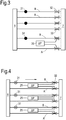
- Figure 3 shows a possible fault detection system.
- the same reference numerals are used in Figure 2 for corresponding components.
- one of the two gas supplying ducts A, B to which the differential pressure sensor 25 is connected may be a modulated-type duct B.
- a modulated-type duct B is a gas supplying duct provided with a flow controller 31.
- the flow controller 31 is configured to switch between a high flow condition in which the flow controller 31 does not restrict gas supply through the modulated-type duct and a low flow condition in which the flow controller 31 substantially reduces gas supply through the modulated-type duct B.
- the flow controller 31 When the flow controller 31 is in the low flow condition, the flow controller may substantially prevent flow through the modulated-type duct B.
- the low flow condition includes there being no flow through the flow controller 31. Of course, even when the flow controller 31 is in the low flow condition, there may be a small flow through the flow controller 31.
- the flow controller 31 may be an open/shut valve. When the flow controller 31 is an open/shut valve, the flow controller 31 may be in the high flow condition when the open/shut valve is in its open position (sometimes called open state). The flow controller 31 may be in the low flow condition when the open/shut valve is in its closed position (sometimes called closed state).
- the open/shut valve may be compact and easy to mount within the modulated-type duct B.
- the flow controller 31 may be a vortex amplifier or a switched vortex valve.
- a vortex amplifier is sometimes called an air transistor.
- an air signal creates a vortex in the flow which controls how much of the air (e.g. cooling air) goes across the chamber.
- a vortex amplifier is an amplifier such that it is possible to modulate the flow with no moving parts. The vortex may be set up with a very small injection of air.
- the other gas supplying duct A connected to the differential pressure sensor 25 is an open-type duct A in which gas supply through the open-duct A is never prevented.
- faults including flow controller failures and burst gas supplying ducts A, B can be detected by looking for unusual pressure differences ⁇ P.
- Flow controller failures that can be detected include whether the flow controller 31 is locked in the high flow condition (i.e. has failed in the high flow condition) or whether the flow controller 31 is locked in the low flow condition (i.e. has failed in the low flow condition). It can also be detected whether the open-type duct A or the modulated-type duct B is burst.
- the pressure in the open-type duct A is greater than the pressure in the modulated-type duct B and the measured pressure difference ⁇ P is greater than the threshold level, it may be determined that the modulated-type duct B is burst. If the pressure in the open-type duct A is ever significantly (i.e. beyond the threshold level) higher than the pressure in the valve-type duct B, there is a break in the valve-type duct B. This is because the only way that the pressure in the modulated-type duct B can be significantly lower than the pressure in the open-type duct A is if the modulated-type duct B is burst.
- the pressure in the modulated-type duct B should be about the same as the pressure in the open-type duct A when the flow controller 31 is in the high flow condition, or should be higher than the pressure in the open-type duct A when the flow controller 31 is in the low flow condition.
- the determination unit of the fault detection system may be configured to determine that the modulated-type duct B is burst when the pressure in the open-type duct A is greater than the pressure in the modulated-type duct B and the measured pressure difference ⁇ P is greater than the threshold level.
- the measured pressure difference ⁇ P it may be the magnitude of the measured pressure difference ⁇ P that is compared to the threshold level.
- the method for detecting a fault may comprise performing two measurements of the pressure difference ⁇ P under two different conditions (i.e. when the flow controller 31 is commanded to be in the high flow condition and when the flow controller 31 is commanded to be in the low flow condition). For example, an initial measurement may be performed when the flow controller 31 is commanded to be in the high flow condition.
- the flow controller 31 being commanded to be in the high flow condition may mean that the flow controller 31 is specifically commanded to be switched to the high flow condition before the measurement is made. Alternatively, it may be known that the flow controller 31 has already been commanded (i.e. is intended) to be in the high flow condition before the measurement is made.
- the flow controller 31 may be commanded to switch to the low flow condition.
- the pressure difference ⁇ P may be re-measured with the flow controller 31 commanded to be in the low flow condition.
- the results of the two measurements of the pressure difference ⁇ P may be compared. In other words, the re-measured pressure difference ⁇ P (commanded to low flow condition) may be compared to the measured pressure difference ⁇ P (commanded to high flow condition).
- the flow controller 31 When the measured pressure difference ⁇ P (commanded to high flow condition) is less than the threshold level and the re-measured pressure difference (commanded to low flow condition) is substantially the same as the measured pressure difference ⁇ P (flow controller commanded to high flow condition), it may be determined that the flow controller 31 is locked in the high flow condition. It is possible to detect that the flow controller 31 is failed in the high flow condition if the pressure difference ⁇ P stays approximately zero when the flow controller 31 is commanded to the low flow condition. The only time when the pressure difference ⁇ P should be approximately zero (and hence below the threshold level) is when there are no breaks in the gas supplying ducts A, B and the flow controller 31 is in the high flow condition.
- the pressure in the modulated-type duct B should be higher than the pressure in the open-type duct A.
- the magnitude of the pressure difference ⁇ P should be medium, which means more than when the flow controller 31 is in the high flow condition but less than when there is a break in one of the gas supplying ducts A, B.
- the fault detection system may be arranged to automatically command the flow controller 31 to switch to the low flow condition, re-measure the pressure difference ⁇ P between the two gas supplying ducts A, B and compare the re-measured pressure difference ⁇ P to the initially measured pressure difference ⁇ P.
- the determination unit may be configured to determine that the flow controller 31 is locked in the high flow condition when the measured pressure difference ⁇ P is less than the threshold level and the re-measured pressure difference ⁇ P is substantially the same as the measured pressure difference ⁇ P.
- the open-type duct A is burst.
- the pressure difference ⁇ P is above the threshold level, then this is an indication that something is wrong. If the pressure difference ⁇ P then increases when the flow controller 31 is commanded shut, this is an indication that the open-type duct A is broken (i.e. burst).
- the determination unit may be configured to determine that the open-type duct A is burst when the measured pressure difference ⁇ P is greater than the threshold level and the re-measured pressure difference is greater than the measured pressure difference ⁇ P.
- the measured pressure difference ⁇ P is greater than the threshold level and the re-measured pressure difference ⁇ P is substantially the same as the measured pressure difference ⁇ P, it may be determined that the flow controller 31 is locked in the low flow condition. If with the flow controller 31 in the high flow condition, the pressure difference ⁇ P is above the threshold level, this is an indication that something is wrong. If the pressure difference ⁇ P does not change when the flow controller 31 is commanded to the low flow condition, then this indicates that the flow controller 31 has failed in the low flow condition.
- the determination unit may be configured to determine that the flow controller 31 is locked in the low flow condition when the pressure in the modulated-type duct B is greater than the pressure in the open-type duct A, the measured pressure difference ⁇ P is greater than the threshold level and the re-measured pressure difference ⁇ P is substantially the same as the measured pressure difference ⁇ P.
- a burst gas supplying duct A, B may produce higher pressure differences due to the throat of the venturi 32 being choked for a burst gas supplying duct A, B but not for a flow controller failure.
- a partial burst occurs in the gas supplying duct A, B in which the flow rate is low, then it may not be possible to differentiate between a burst duct and a failed flow controller.
- the initial measurement may be performed with the flow controller 31 commanded to be in the low flow condition
- the subsequent re-measurement may be performed after the flow controller 31 has been commanded to switch to the high flow condition.
- the pressure in the open-type duct A is greater than the pressure in the modulated-type duct B and the (initially) measured pressure difference ⁇ P is greater than the threshold level, it may be determined that the modulated-type duct B is burst.
- the initially measured (flow controller 31 commanded to the low flow condition) pressure difference ⁇ P is greater than the threshold level and the re-measured (flow controller 31 commanded to the high flow condition) pressure difference ⁇ P is substantially the same as the initially measured (flow controller 31 commanded to low flow condition) pressure difference ⁇ P, it may be determined that the flow controller 31 is locked (i.e. has failed) in low flow condition.
- Figure 4 shows a possible fault detection system.
- the arrow at the top of the Figure extending from left to right shows the direction of gas flow when there is no fault in the gas supply system 5 supplying gas from the gas supplying component 6 to the gas receiving component 7.
- the gas supply system 5 may comprise a plurality of modulated-type ducts B and a corresponding plurality of open-type ducts A.
- Each modulated-type duct B may be paired up with a corresponding open-type duct A.
- the fault detection system may comprise a corresponding plurality of differential pressure sensors 25.
- Each differential pressure sensor 25 may be for measuring a pressure difference ⁇ P between one of the modulated-type ducts B and a corresponding one of the open-type ducts A.
- the comparison unit may be for comparing, for each differential pressure sensor 25, the measured pressure difference ⁇ P to the threshold level.
- the determination unit may be for determining, for each measured pressure difference ⁇ P and comparison, a fault based on the measured pressure difference ⁇ P and the comparison.
- the gas supply system 5 may be designed to provide enough flow at high power/low altitude condition (e.g. during take off) and enough flow to over supply the gas receiving component 7 (e.g. turbine) during cruise conditions.
- gas receiving component 7 e.g. turbine
- the air flow e.g. used to cool the blades of the turbines 16, 17, 18
- the air flow is modulated by turning it down when not so much is needed.
- Venturis 32 may be provided to limit this flow.
- the venturis 32 may not be provided to all of the gas supplying ducts 5. For example, it may be that only the open-type ducts A contain venturis 32.
- An embodiment of the invention is expected to ensure that no single control failure can lead to a hazardous condition.
- gas supplying ducts A, B it is not necessary for the gas supplying ducts A, B to be provided in pairs connected by a common differential pressure sensor 25. Instead, it is possible to link one duct to two ducts. For example, this may be desirable if there are unequal numbers of open-type ducts A and modulated-type ducts B.
- the gas supply system 5 may be arranged such that all of the modulated-type ducts B contain a venturi 32. It may be that only one of the open-type ducts A has a venturi 32. In this case, all of the modulated-type ducts B may be linked to the open-type duct A that has the venturi 32 via corresponding differential pressure sensors 25. In such a construction it may not be possible to detect whether one of the open-type ducts A that does not contain any venturi 32 is burst. However, by reducing the number of venturis 32 in the gas supply system 5, cost and weight of the gas supply system may be reduced.
- the threshold level may differ depending on whether or not the pressure in the open-type duct A is greater than the pressure in the modulated-type duct B.
- the threshold level may be calculated based on a current engine condition of the gas turbine engine 10 and/or altitude of the gas turbine engine 10.
- the throat position within the venturi 32 may be considered to be the "sweet spot" in terms of maximising the sensitivity of detection.
- the fault detection system may be cheaper, lighter and more reliable.
- the actuation system for the flow controllers may be designed so that such a common failure is sufficiently unlikely.
- a pair of gas supplying ducts A, B may be provided with two differential pressure sensors 25. This accommodates the possibility that one of the differential pressure sensors 25 fails during a flight. Introducing redundancy into the system improves its reliability.
- the invention may be quicker, easier and more reliable to detect a failure in the gas supply system 5 within a single flight. This reduces the possibility of damage to components of the aircraft resulting from failure of the gas supply system 5.
- urgent maintenance can be carried out at an earlier stage because the fault has been detected at an earlier stage.
- aspects of the disclosure relate to providing a gas supply system 5 for supplying gas from a compressor source to a turbine in a gas turbine engine, it will be appreciated that the gas supply system could supply gas from and to different components.
- the disclosure relates to the exemplary arrangements/methods described above, many equivalent modifications and variations will be apparent to those skilled in the art when given this disclosure. Accordingly, the exemplary arrangements/methods set fourth above are considered to be illustrative and not limiting. Various changes to the described arrangements/methods may be made without departing from the scope of the invention.
- gas supply system may be any type of gas supply system, including, but not limited to, a turbine cooling system, a bearing oil control system and a cabin air system. Aspects of the disclosure may be applicable, for example, to any gas supply system comprising ducts. Any feature described and/or claimed herein may be combined with any other compatible feature described in relation to the same or another embodiment.
Landscapes
- Engineering & Computer Science (AREA)
- Chemical & Material Sciences (AREA)
- Combustion & Propulsion (AREA)
- Physics & Mathematics (AREA)
- General Physics & Mathematics (AREA)
- Mechanical Engineering (AREA)
- General Engineering & Computer Science (AREA)
- Measuring Volume Flow (AREA)
Claims (11)
- Procédé pour détecter un défaut dans un système d'alimentation en gaz (5) de moteur de turbine à gaz, le procédé comprenant les étapes consistant à :mesurer une différence de pression (ΔP) entre deux conduites d'alimentation en gaz (A, B) du système d'alimentation en gaz (5) ;comparer la différence de pression (ΔP) mesurée à un niveau seuil ; etdéterminer un défaut en fonction de la différence de pression (ΔP) mesurée et de la comparaison, caractérisé en ce que :une des deux conduites d'alimentation en gaz (A, B) est une conduite de type modulé (B) munie d'un régulateur de débit (31) conçue pour commuter entre une condition de débit élevé dans laquelle le régulateur de débit (31) ne restreint pas l'alimentation en gaz à travers la conduite de type modulé (B) et une condition de débit faible dans laquelle le régulateur de débit (31) réduit sensiblement l'alimentation en gaz à travers la conduite de type modulé (B) ; etl'autre des deux conduites d'alimentation en gaz (A, B) est une conduite de type ouvert (A) conçue pour rester ouverte pour l'alimentation en gaz à travers la conduite de type ouvert (A), etchacune des conduites d'alimentation en gaz (A, B) étant munie d'un venturi (32) à une position de venturi pour restreindre le flux à travers la conduite d'alimentation en gaz (A, B) ; etun capteur de pression différentielle (25) étant conçu pour mesurer la différence de pression (ΔP) entre les positions de venturi des deux conduites d'alimentation en gaz (A, B).
- Procédé selon la revendication 1, au cours duquel, lorsque la pression dans la conduite de type ouvert (A) est supérieure à la pression dans la conduite de type modulé (B) et la différence de pression (ΔP) mesurée est supérieure au niveau seuil, il est déterminé que la conduite de type modulé (B) est éclatée.
- Procédé selon la revendication 1 :la mesure de la différence de pression (ΔP) s'effectuant lorsque le régulateur de débit (31) est commandé pour être en condition de débit élevé ; etle procédé comprenant les étapes consistant à commander au régulateur de débit (31) de passer à la condition de débit faible, à mesurer à nouveau une différence de pression (ΔP) entre les deux conduites d'alimentation en gaz (A, B) et à comparer la différence de pression (ΔP) mesurée à nouveau à la différence de pression (ΔP) mesurée.
- Procédé selon la revendication 3, au cours duquel, lorsque la différence de pression (ΔP) mesurée, dans la condition de débit élevé, est inférieure au niveau seuil et la différence de pression (ΔP) mesurée à nouveau, dans la condition de débit faible, est sensiblement la même que la différence de pression (ΔP) mesurée, il est déterminé que le régulateur de débit (31) est verrouillé dans la condition de débit élevé.
- Procédé selon la revendication 3 ou 4, au cours duquel, lorsque la différence de pression (ΔP) mesurée, dans la condition de débit élevé, est supérieure au niveau seuil et la différence de pression (ΔP) mesurée à nouveau, dans la condition de débit faible, est supérieure à la différence de pression (ΔP) mesurée, dans la condition de débit élevé, il est déterminé que la conduite de type ouvert (A) est éclatée.
- Procédé selon l'une quelconque des revendications 3 à 5, au cours duquel, lorsque la pression dans la conduite de type modulé (B) est supérieure à la pression dans la conduite de type ouvert (A), la différence de pression (ΔP) mesurée, dans la condition de débit élevé, est inférieure au niveau seuil et la différence de pression (ΔP) mesurée à nouveau, dans la condition de débit faible, est sensiblement la même que la différence de pression (ΔP) mesurée, il est déterminé que le régulateur de débit (31) est verrouillé dans la condition de débit faible.
- Procédé selon l'une quelconque des revendications précédentes, le niveau seuil différant selon que la pression dans la conduite de type ouvert (A) est supérieure ou non à la pression dans la conduite de type modulé (B).
- Procédé selon l'une quelconque des revendications précédentes, le niveau seuil étant calculé en fonction d'une condition de moteur actuelle du moteur de turbine à gaz (10) et/ou de l'altitude du moteur de turbine à gaz (10).
- Moteur de turbine à gaz (10) comprenant :un système de détection de défaut pour détecter un défaut dans un système d'alimentation en gaz (5) de moteur de turbine à gaz, le système de détection de défaut comprenant :un capteur de pression différentielle (25) pour mesurer une différence de pression (ΔP) entre deux conduites d'alimentation en gaz (A, B) du système d'alimentation en gaz (5) ;une unité de comparaison pour comparer la différence de pression (ΔP) mesurée à un niveau seuil ; etune unité de détermination pour déterminer un défaut en fonction de la différence de pression (ΔP) mesurée et de la comparaison ; et le moteur de turbine à gaz comprenant en outre :le système d'alimentation en gaz (5), caractérisé en ce que :une des deux conduites d'alimentation en gaz (A, B) est une conduite de type modulé (B) munie d'un régulateur de débit (31) conçue pour commuter entre une condition de débit élevé dans laquelle le régulateur de débit (31) ne restreint pas l'alimentation en gaz à travers la conduite de type modulé (B) et une condition de débit faible dans laquelle le régulateur de débit (31) réduit sensiblement l'alimentation en gaz à travers la conduite de type modulé (B) ; etl'autre des deux conduites d'alimentation en gaz (A, B) est une conduite de type ouvert (A) conçue pour rester ouverte pour l'alimentation en gaz à travers la conduite de type ouvert (A), etchacune des conduites d'alimentation en gaz (A, B) étant munie d'un venturi (32) à une position de venturi pour restreindre le flux à travers la conduite d'alimentation en gaz (A, B) ; etle capteur de pression différentielle (25) étant conçu pour mesurer la différence de pression (ΔP) entre les positions de venturi des deux conduites d'alimentation en gaz (A, B).
- Moteur de turbine à gaz (10) selon la revendication 9 :le système d'alimentation en gaz (5) comprenant une pluralité de conduites de type modulé (B) et une pluralité correspondante de conduites de type ouvert (A) ;le système de détection de défaut comprenant une pluralité correspondante de capteurs de pression différentielle (25), chacun pour mesurer une différence de pression (ΔP) entre l'une des conduites de type modulé (B) et l'une correspondant des conduites de type ouvert (A) ;l'unité de comparaison servant à comparer, pour chaque capteur de pression différentielle (25), la différence de pression (ΔP) mesurée au niveau seuil ; etl'unité de détermination servant à déterminer, pour chaque différence de pression (ΔP) mesurée et comparaison, un défaut en fonction de la différence de pression (ΔP) mesurée et de la comparaison.
- Moteur de turbine à gaz (10) selon la revendication 9 :le système d'alimentation en gaz (5) comprenant une pluralité de conduites de type modulé (B) ;le système de détection de défaut comprenant une pluralité correspondante de capteurs de pression différentielle (25), chacun pour mesurer une différence de pression (ΔP) entre la conduite de type ouvert (A) et l'une des conduites de type modulé (B) ;l'unité de comparaison servant à comparer, pour chaque capteur de pression différentielle (25), la différence de pression (ΔP) mesurée au niveau seuil ; etl'unité de détermination servant à déterminer, pour chaque différence de pression (ΔP) mesurée et comparaison, un défaut en fonction de la différence de pression (ΔP) mesurée et de la comparaison.
Applications Claiming Priority (1)
| Application Number | Priority Date | Filing Date | Title |
|---|---|---|---|
| GBGB1500838.6A GB201500838D0 (en) | 2015-01-19 | 2015-01-19 | Method for detecting a fault, fault detection system and gas turbine engine |
Publications (2)
| Publication Number | Publication Date |
|---|---|
| EP3045887A1 EP3045887A1 (fr) | 2016-07-20 |
| EP3045887B1 true EP3045887B1 (fr) | 2018-04-25 |
Family
ID=52630774
Family Applications (1)
| Application Number | Title | Priority Date | Filing Date |
|---|---|---|---|
| EP15201517.8A Not-in-force EP3045887B1 (fr) | 2015-01-19 | 2015-12-21 | Procédé pour la détection d'un défaut, système de détection de défaut et moteur de turbine à gaz |
Country Status (3)
| Country | Link |
|---|---|
| US (1) | US10487749B2 (fr) |
| EP (1) | EP3045887B1 (fr) |
| GB (1) | GB201500838D0 (fr) |
Families Citing this family (3)
| Publication number | Priority date | Publication date | Assignee | Title |
|---|---|---|---|---|
| US11280213B2 (en) * | 2017-04-19 | 2022-03-22 | General Electric Company | Fluid supply line leakage detection system and method |
| US11713692B2 (en) * | 2018-06-22 | 2023-08-01 | Textron Innovations Inc. | Real time engine inlet barrier filter condition monitor |
| US11821324B2 (en) * | 2022-04-25 | 2023-11-21 | General Electric Company | Duct failure detection in a turbine engine |
Family Cites Families (14)
| Publication number | Priority date | Publication date | Assignee | Title |
|---|---|---|---|---|
| GB859490A (en) * | 1958-10-14 | 1961-01-25 | Thompson Nuclear Energy Co Ltd | Improvements relating to apparatus for detecting leaks in gas flow ducts |
| US4028888A (en) * | 1974-05-03 | 1977-06-14 | Norwalk-Turbo Inc. | Fuel distribution manifold to an annular combustion chamber |
| GB8920695D0 (en) * | 1989-09-13 | 1989-10-25 | Rolls Royce Plc | Engine cooling system protection device |
| US5261452A (en) | 1991-03-01 | 1993-11-16 | American Air Liquide | Critical orifice dilution system and method |
| US5155991A (en) | 1991-04-01 | 1992-10-20 | United Technologies Corporation | Bleed air flow regulators with flow balance |
| US5161364A (en) * | 1991-04-01 | 1992-11-10 | United Technologies Corporation | Control of aircraft bleed air stage mixing |
| US6526358B1 (en) | 1999-10-01 | 2003-02-25 | General Electric Company | Model-based detection of leaks and blockages in fluid handling systems |
| DE10217499C1 (de) * | 2002-04-19 | 2003-07-24 | Draeger Aerospace Gmbh | Sicherheitsvorrichtung für ein Gas-Verteilungssystem in einem Flugzeug |
| US6799112B1 (en) * | 2003-10-03 | 2004-09-28 | General Electric Company | Methods and apparatus for operating gas turbine engines |
| US8033118B2 (en) * | 2008-01-31 | 2011-10-11 | EMBRAER—Empresa Brasileira de Aeronautica S.A. | Bleed airflow balancing control using simplified sensing |
| FR2976255B1 (fr) * | 2011-06-09 | 2013-12-20 | Snecma | Dispositif de controle d'un systeme de prelevement d'air d'un aeronef |
| US8843253B1 (en) | 2013-04-02 | 2014-09-23 | Honeywell International Inc. | Aircraft ice protection control system and method for mitigating engine over-bleed |
| GB2513132B (en) * | 2013-04-16 | 2015-05-27 | Ge Aviat Systems Ltd | Method for predicting a bleed air system fault |
| US9546604B2 (en) * | 2015-01-08 | 2017-01-17 | United Technologies Corporation | Transient fault detection methods and systems |
-
2015
- 2015-01-19 GB GBGB1500838.6A patent/GB201500838D0/en not_active Ceased
- 2015-12-21 US US14/976,525 patent/US10487749B2/en not_active Expired - Fee Related
- 2015-12-21 EP EP15201517.8A patent/EP3045887B1/fr not_active Not-in-force
Non-Patent Citations (1)
| Title |
|---|
| None * |
Also Published As
| Publication number | Publication date |
|---|---|
| US10487749B2 (en) | 2019-11-26 |
| EP3045887A1 (fr) | 2016-07-20 |
| US20160208716A1 (en) | 2016-07-21 |
| GB201500838D0 (en) | 2015-03-04 |
Similar Documents
| Publication | Publication Date | Title |
|---|---|---|
| JP5584430B2 (ja) | 過回転防止を可能にする方法及びシステム | |
| US8321119B2 (en) | Methods and systems to facilitate over-speed protection | |
| US9771906B2 (en) | Engine fuel control system | |
| EP3242006B1 (fr) | Procédé de détermination d'un état d'une soupape et appareil de surveillance de soupape | |
| EP3141724B1 (fr) | Détection de fuite de soupape d'étage supérieur par verrouillage de pression | |
| EP3043097B1 (fr) | Procédés de détection de défaillance transitoire et systèmes | |
| EP3792466B1 (fr) | Moniteur de santé pour soupape de commutation d'un système de prélèvement d'air de turbine à gaz | |
| US10900880B2 (en) | Cabin air control system for an aircraft | |
| US9995222B2 (en) | High temperature disk conditioning system | |
| US20100005657A1 (en) | Methods and systems to facilitate over-speed protection | |
| US10487749B2 (en) | Method for detecting a fault, fault detection system and gas turbine engine | |
| US10253699B2 (en) | Device and method for testing the integrity of a helicopter turbine engine rapid restart system | |
| US20200141262A1 (en) | Engine with temperature sensor in a flow path of a flow carrying fluid at a higher temperature in the event of a fault, and method for the electronic detection of a fault during operation of an engine | |
| EP1753939B1 (fr) | Limiteur de survitesse pour turbomoteurs | |
| EP3415434A1 (fr) | Diagnostic de défaillance pour un système à deux valves d'un système anti-glace de nacelle | |
| US10054002B2 (en) | Method for assisting with the detection of damage to a turbojet duct | |
| US11821324B2 (en) | Duct failure detection in a turbine engine | |
| US20250264109A1 (en) | System and method for detecting a performance degradation of a bleed-off valve | |
| GB2461609A (en) | Method and system to facilitate over-speed protection |
Legal Events
| Date | Code | Title | Description |
|---|---|---|---|
| PUAI | Public reference made under article 153(3) epc to a published international application that has entered the european phase |
Free format text: ORIGINAL CODE: 0009012 |
|
| AK | Designated contracting states |
Kind code of ref document: A1 Designated state(s): AL AT BE BG CH CY CZ DE DK EE ES FI FR GB GR HR HU IE IS IT LI LT LU LV MC MK MT NL NO PL PT RO RS SE SI SK SM TR |
|
| AX | Request for extension of the european patent |
Extension state: BA ME |
|
| STAA | Information on the status of an ep patent application or granted ep patent |
Free format text: STATUS: REQUEST FOR EXAMINATION WAS MADE |
|
| 17P | Request for examination filed |
Effective date: 20161222 |
|
| RBV | Designated contracting states (corrected) |
Designated state(s): AL AT BE BG CH CY CZ DE DK EE ES FI FR GB GR HR HU IE IS IT LI LT LU LV MC MK MT NL NO PL PT RO RS SE SI SK SM TR |
|
| REG | Reference to a national code |
Ref country code: DE Ref legal event code: R079 Ref document number: 602015010372 Country of ref document: DE Free format text: PREVIOUS MAIN CLASS: G01M0003280000 Ipc: F02C0009260000 |
|
| RIC1 | Information provided on ipc code assigned before grant |
Ipc: F02C 9/00 20060101ALI20180111BHEP Ipc: F02C 6/08 20060101ALI20180111BHEP Ipc: G01M 3/28 20060101ALI20180111BHEP Ipc: F02C 9/26 20060101AFI20180111BHEP Ipc: G01M 15/14 20060101ALI20180111BHEP |
|
| GRAP | Despatch of communication of intention to grant a patent |
Free format text: ORIGINAL CODE: EPIDOSNIGR1 |
|
| STAA | Information on the status of an ep patent application or granted ep patent |
Free format text: STATUS: GRANT OF PATENT IS INTENDED |
|
| GRAS | Grant fee paid |
Free format text: ORIGINAL CODE: EPIDOSNIGR3 |
|
| INTG | Intention to grant announced |
Effective date: 20180222 |
|
| GRAA | (expected) grant |
Free format text: ORIGINAL CODE: 0009210 |
|
| STAA | Information on the status of an ep patent application or granted ep patent |
Free format text: STATUS: THE PATENT HAS BEEN GRANTED |
|
| AK | Designated contracting states |
Kind code of ref document: B1 Designated state(s): AL AT BE BG CH CY CZ DE DK EE ES FI FR GB GR HR HU IE IS IT LI LT LU LV MC MK MT NL NO PL PT RO RS SE SI SK SM TR |
|
| REG | Reference to a national code |
Ref country code: GB Ref legal event code: FG4D |
|
| REG | Reference to a national code |
Ref country code: CH Ref legal event code: EP |
|
| REG | Reference to a national code |
Ref country code: AT Ref legal event code: REF Ref document number: 993175 Country of ref document: AT Kind code of ref document: T Effective date: 20180515 |
|
| REG | Reference to a national code |
Ref country code: IE Ref legal event code: FG4D |
|
| REG | Reference to a national code |
Ref country code: DE Ref legal event code: R096 Ref document number: 602015010372 Country of ref document: DE |
|
| REG | Reference to a national code |
Ref country code: NL Ref legal event code: MP Effective date: 20180425 |
|
| REG | Reference to a national code |
Ref country code: LT Ref legal event code: MG4D |
|
| PG25 | Lapsed in a contracting state [announced via postgrant information from national office to epo] |
Ref country code: NL Free format text: LAPSE BECAUSE OF FAILURE TO SUBMIT A TRANSLATION OF THE DESCRIPTION OR TO PAY THE FEE WITHIN THE PRESCRIBED TIME-LIMIT Effective date: 20180425 |
|
| PG25 | Lapsed in a contracting state [announced via postgrant information from national office to epo] |
Ref country code: BG Free format text: LAPSE BECAUSE OF FAILURE TO SUBMIT A TRANSLATION OF THE DESCRIPTION OR TO PAY THE FEE WITHIN THE PRESCRIBED TIME-LIMIT Effective date: 20180725 Ref country code: FI Free format text: LAPSE BECAUSE OF FAILURE TO SUBMIT A TRANSLATION OF THE DESCRIPTION OR TO PAY THE FEE WITHIN THE PRESCRIBED TIME-LIMIT Effective date: 20180425 Ref country code: SE Free format text: LAPSE BECAUSE OF FAILURE TO SUBMIT A TRANSLATION OF THE DESCRIPTION OR TO PAY THE FEE WITHIN THE PRESCRIBED TIME-LIMIT Effective date: 20180425 Ref country code: NO Free format text: LAPSE BECAUSE OF FAILURE TO SUBMIT A TRANSLATION OF THE DESCRIPTION OR TO PAY THE FEE WITHIN THE PRESCRIBED TIME-LIMIT Effective date: 20180725 Ref country code: PL Free format text: LAPSE BECAUSE OF FAILURE TO SUBMIT A TRANSLATION OF THE DESCRIPTION OR TO PAY THE FEE WITHIN THE PRESCRIBED TIME-LIMIT Effective date: 20180425 Ref country code: LT Free format text: LAPSE BECAUSE OF FAILURE TO SUBMIT A TRANSLATION OF THE DESCRIPTION OR TO PAY THE FEE WITHIN THE PRESCRIBED TIME-LIMIT Effective date: 20180425 Ref country code: ES Free format text: LAPSE BECAUSE OF FAILURE TO SUBMIT A TRANSLATION OF THE DESCRIPTION OR TO PAY THE FEE WITHIN THE PRESCRIBED TIME-LIMIT Effective date: 20180425 |
|
| PG25 | Lapsed in a contracting state [announced via postgrant information from national office to epo] |
Ref country code: HR Free format text: LAPSE BECAUSE OF FAILURE TO SUBMIT A TRANSLATION OF THE DESCRIPTION OR TO PAY THE FEE WITHIN THE PRESCRIBED TIME-LIMIT Effective date: 20180425 Ref country code: RS Free format text: LAPSE BECAUSE OF FAILURE TO SUBMIT A TRANSLATION OF THE DESCRIPTION OR TO PAY THE FEE WITHIN THE PRESCRIBED TIME-LIMIT Effective date: 20180425 Ref country code: GR Free format text: LAPSE BECAUSE OF FAILURE TO SUBMIT A TRANSLATION OF THE DESCRIPTION OR TO PAY THE FEE WITHIN THE PRESCRIBED TIME-LIMIT Effective date: 20180726 Ref country code: LV Free format text: LAPSE BECAUSE OF FAILURE TO SUBMIT A TRANSLATION OF THE DESCRIPTION OR TO PAY THE FEE WITHIN THE PRESCRIBED TIME-LIMIT Effective date: 20180425 |
|
| REG | Reference to a national code |
Ref country code: AT Ref legal event code: MK05 Ref document number: 993175 Country of ref document: AT Kind code of ref document: T Effective date: 20180425 |
|
| PG25 | Lapsed in a contracting state [announced via postgrant information from national office to epo] |
Ref country code: PT Free format text: LAPSE BECAUSE OF FAILURE TO SUBMIT A TRANSLATION OF THE DESCRIPTION OR TO PAY THE FEE WITHIN THE PRESCRIBED TIME-LIMIT Effective date: 20180827 |
|
| REG | Reference to a national code |
Ref country code: DE Ref legal event code: R097 Ref document number: 602015010372 Country of ref document: DE |
|
| PG25 | Lapsed in a contracting state [announced via postgrant information from national office to epo] |
Ref country code: SK Free format text: LAPSE BECAUSE OF FAILURE TO SUBMIT A TRANSLATION OF THE DESCRIPTION OR TO PAY THE FEE WITHIN THE PRESCRIBED TIME-LIMIT Effective date: 20180425 Ref country code: RO Free format text: LAPSE BECAUSE OF FAILURE TO SUBMIT A TRANSLATION OF THE DESCRIPTION OR TO PAY THE FEE WITHIN THE PRESCRIBED TIME-LIMIT Effective date: 20180425 Ref country code: DK Free format text: LAPSE BECAUSE OF FAILURE TO SUBMIT A TRANSLATION OF THE DESCRIPTION OR TO PAY THE FEE WITHIN THE PRESCRIBED TIME-LIMIT Effective date: 20180425 Ref country code: AT Free format text: LAPSE BECAUSE OF FAILURE TO SUBMIT A TRANSLATION OF THE DESCRIPTION OR TO PAY THE FEE WITHIN THE PRESCRIBED TIME-LIMIT Effective date: 20180425 Ref country code: EE Free format text: LAPSE BECAUSE OF FAILURE TO SUBMIT A TRANSLATION OF THE DESCRIPTION OR TO PAY THE FEE WITHIN THE PRESCRIBED TIME-LIMIT Effective date: 20180425 Ref country code: CZ Free format text: LAPSE BECAUSE OF FAILURE TO SUBMIT A TRANSLATION OF THE DESCRIPTION OR TO PAY THE FEE WITHIN THE PRESCRIBED TIME-LIMIT Effective date: 20180425 |
|
| PG25 | Lapsed in a contracting state [announced via postgrant information from national office to epo] |
Ref country code: IT Free format text: LAPSE BECAUSE OF FAILURE TO SUBMIT A TRANSLATION OF THE DESCRIPTION OR TO PAY THE FEE WITHIN THE PRESCRIBED TIME-LIMIT Effective date: 20180425 Ref country code: SM Free format text: LAPSE BECAUSE OF FAILURE TO SUBMIT A TRANSLATION OF THE DESCRIPTION OR TO PAY THE FEE WITHIN THE PRESCRIBED TIME-LIMIT Effective date: 20180425 |
|
| PLBE | No opposition filed within time limit |
Free format text: ORIGINAL CODE: 0009261 |
|
| STAA | Information on the status of an ep patent application or granted ep patent |
Free format text: STATUS: NO OPPOSITION FILED WITHIN TIME LIMIT |
|
| 26N | No opposition filed |
Effective date: 20190128 |
|
| PG25 | Lapsed in a contracting state [announced via postgrant information from national office to epo] |
Ref country code: SI Free format text: LAPSE BECAUSE OF FAILURE TO SUBMIT A TRANSLATION OF THE DESCRIPTION OR TO PAY THE FEE WITHIN THE PRESCRIBED TIME-LIMIT Effective date: 20180425 |
|
| REG | Reference to a national code |
Ref country code: CH Ref legal event code: PL |
|
| PG25 | Lapsed in a contracting state [announced via postgrant information from national office to epo] |
Ref country code: MC Free format text: LAPSE BECAUSE OF FAILURE TO SUBMIT A TRANSLATION OF THE DESCRIPTION OR TO PAY THE FEE WITHIN THE PRESCRIBED TIME-LIMIT Effective date: 20180425 Ref country code: LU Free format text: LAPSE BECAUSE OF NON-PAYMENT OF DUE FEES Effective date: 20181221 |
|
| REG | Reference to a national code |
Ref country code: IE Ref legal event code: MM4A |
|
| REG | Reference to a national code |
Ref country code: BE Ref legal event code: MM Effective date: 20181231 |
|
| PG25 | Lapsed in a contracting state [announced via postgrant information from national office to epo] |
Ref country code: IE Free format text: LAPSE BECAUSE OF NON-PAYMENT OF DUE FEES Effective date: 20181221 |
|
| PG25 | Lapsed in a contracting state [announced via postgrant information from national office to epo] |
Ref country code: AL Free format text: LAPSE BECAUSE OF FAILURE TO SUBMIT A TRANSLATION OF THE DESCRIPTION OR TO PAY THE FEE WITHIN THE PRESCRIBED TIME-LIMIT Effective date: 20180425 Ref country code: BE Free format text: LAPSE BECAUSE OF NON-PAYMENT OF DUE FEES Effective date: 20181231 |
|
| PG25 | Lapsed in a contracting state [announced via postgrant information from national office to epo] |
Ref country code: LI Free format text: LAPSE BECAUSE OF NON-PAYMENT OF DUE FEES Effective date: 20181231 Ref country code: CH Free format text: LAPSE BECAUSE OF NON-PAYMENT OF DUE FEES Effective date: 20181231 |
|
| PG25 | Lapsed in a contracting state [announced via postgrant information from national office to epo] |
Ref country code: MT Free format text: LAPSE BECAUSE OF NON-PAYMENT OF DUE FEES Effective date: 20181221 |
|
| PGFP | Annual fee paid to national office [announced via postgrant information from national office to epo] |
Ref country code: FR Payment date: 20191226 Year of fee payment: 5 |
|
| PG25 | Lapsed in a contracting state [announced via postgrant information from national office to epo] |
Ref country code: TR Free format text: LAPSE BECAUSE OF FAILURE TO SUBMIT A TRANSLATION OF THE DESCRIPTION OR TO PAY THE FEE WITHIN THE PRESCRIBED TIME-LIMIT Effective date: 20180425 |
|
| PGFP | Annual fee paid to national office [announced via postgrant information from national office to epo] |
Ref country code: DE Payment date: 20191231 Year of fee payment: 5 Ref country code: GB Payment date: 20200102 Year of fee payment: 5 |
|
| PG25 | Lapsed in a contracting state [announced via postgrant information from national office to epo] |
Ref country code: CY Free format text: LAPSE BECAUSE OF FAILURE TO SUBMIT A TRANSLATION OF THE DESCRIPTION OR TO PAY THE FEE WITHIN THE PRESCRIBED TIME-LIMIT Effective date: 20180425 Ref country code: HU Free format text: LAPSE BECAUSE OF FAILURE TO SUBMIT A TRANSLATION OF THE DESCRIPTION OR TO PAY THE FEE WITHIN THE PRESCRIBED TIME-LIMIT; INVALID AB INITIO Effective date: 20151221 Ref country code: MK Free format text: LAPSE BECAUSE OF NON-PAYMENT OF DUE FEES Effective date: 20180425 |
|
| PG25 | Lapsed in a contracting state [announced via postgrant information from national office to epo] |
Ref country code: IS Free format text: LAPSE BECAUSE OF FAILURE TO SUBMIT A TRANSLATION OF THE DESCRIPTION OR TO PAY THE FEE WITHIN THE PRESCRIBED TIME-LIMIT Effective date: 20180825 |
|
| REG | Reference to a national code |
Ref country code: DE Ref legal event code: R119 Ref document number: 602015010372 Country of ref document: DE |
|
| GBPC | Gb: european patent ceased through non-payment of renewal fee |
Effective date: 20201221 |
|
| PG25 | Lapsed in a contracting state [announced via postgrant information from national office to epo] |
Ref country code: FR Free format text: LAPSE BECAUSE OF NON-PAYMENT OF DUE FEES Effective date: 20201231 |
|
| PG25 | Lapsed in a contracting state [announced via postgrant information from national office to epo] |
Ref country code: GB Free format text: LAPSE BECAUSE OF NON-PAYMENT OF DUE FEES Effective date: 20201221 Ref country code: DE Free format text: LAPSE BECAUSE OF NON-PAYMENT OF DUE FEES Effective date: 20210701 |