EP3045929A1 - Detecteur pour détecter des mouvements d'un patient dans un système d'imagerie - Google Patents
Detecteur pour détecter des mouvements d'un patient dans un système d'imagerie Download PDFInfo
- Publication number
- EP3045929A1 EP3045929A1 EP15199836.6A EP15199836A EP3045929A1 EP 3045929 A1 EP3045929 A1 EP 3045929A1 EP 15199836 A EP15199836 A EP 15199836A EP 3045929 A1 EP3045929 A1 EP 3045929A1
- Authority
- EP
- European Patent Office
- Prior art keywords
- patient
- motion sensor
- resonator
- sensor according
- res
- Prior art date
- Legal status (The legal status is an assumption and is not a legal conclusion. Google has not performed a legal analysis and makes no representation as to the accuracy of the status listed.)
- Withdrawn
Links
- 230000033001 locomotion Effects 0.000 title claims abstract description 53
- 238000003384 imaging method Methods 0.000 title claims abstract description 10
- 238000001514 detection method Methods 0.000 title claims abstract description 8
- 238000002595 magnetic resonance imaging Methods 0.000 claims abstract description 18
- 238000000034 method Methods 0.000 claims abstract description 5
- 230000005540 biological transmission Effects 0.000 claims description 16
- 238000003325 tomography Methods 0.000 claims description 9
- 230000008878 coupling Effects 0.000 claims description 7
- 238000010168 coupling process Methods 0.000 claims description 7
- 238000005859 coupling reaction Methods 0.000 claims description 7
- 230000000241 respiratory effect Effects 0.000 claims description 7
- 230000008859 change Effects 0.000 claims description 6
- 230000001939 inductive effect Effects 0.000 claims description 6
- 230000002123 temporal effect Effects 0.000 claims description 5
- 210000003484 anatomy Anatomy 0.000 claims description 4
- 239000003990 capacitor Substances 0.000 claims description 4
- 238000006073 displacement reaction Methods 0.000 claims description 4
- 230000003187 abdominal effect Effects 0.000 claims description 3
- 238000002059 diagnostic imaging Methods 0.000 claims description 2
- 230000005672 electromagnetic field Effects 0.000 claims description 2
- 230000003993 interaction Effects 0.000 claims description 2
- ZOXJGFHDIHLPTG-UHFFFAOYSA-N Boron Chemical compound [B] ZOXJGFHDIHLPTG-UHFFFAOYSA-N 0.000 claims 1
- 229910052796 boron Inorganic materials 0.000 claims 1
- 210000000481 breast Anatomy 0.000 claims 1
- 230000001419 dependent effect Effects 0.000 claims 1
- 238000005259 measurement Methods 0.000 description 16
- 230000029058 respiratory gaseous exchange Effects 0.000 description 8
- 230000005284 excitation Effects 0.000 description 4
- 230000006870 function Effects 0.000 description 3
- 239000011159 matrix material Substances 0.000 description 3
- 238000011156 evaluation Methods 0.000 description 2
- 238000001208 nuclear magnetic resonance pulse sequence Methods 0.000 description 2
- 238000012545 processing Methods 0.000 description 2
- 230000004888 barrier function Effects 0.000 description 1
- 238000011161 development Methods 0.000 description 1
- 230000018109 developmental process Effects 0.000 description 1
- 238000003745 diagnosis Methods 0.000 description 1
- 230000002349 favourable effect Effects 0.000 description 1
- 210000003205 muscle Anatomy 0.000 description 1
- 210000000056 organ Anatomy 0.000 description 1
- 230000005855 radiation Effects 0.000 description 1
- 229940121896 radiopharmaceutical Drugs 0.000 description 1
- 239000012217 radiopharmaceutical Substances 0.000 description 1
- 230000002799 radiopharmaceutical effect Effects 0.000 description 1
- 230000008054 signal transmission Effects 0.000 description 1
- 238000001228 spectrum Methods 0.000 description 1
- 230000003068 static effect Effects 0.000 description 1
- 230000009466 transformation Effects 0.000 description 1
- 238000002834 transmittance Methods 0.000 description 1
- 238000011144 upstream manufacturing Methods 0.000 description 1
Images

Classifications
-
- G—PHYSICS
- G01—MEASURING; TESTING
- G01R—MEASURING ELECTRIC VARIABLES; MEASURING MAGNETIC VARIABLES
- G01R33/00—Arrangements or instruments for measuring magnetic variables
- G01R33/20—Arrangements or instruments for measuring magnetic variables involving magnetic resonance
- G01R33/44—Arrangements or instruments for measuring magnetic variables involving magnetic resonance using nuclear magnetic resonance [NMR]
- G01R33/48—NMR imaging systems
- G01R33/54—Signal processing systems, e.g. using pulse sequences ; Generation or control of pulse sequences; Operator console
- G01R33/56—Image enhancement or correction, e.g. subtraction or averaging techniques, e.g. improvement of signal-to-noise ratio and resolution
- G01R33/567—Image enhancement or correction, e.g. subtraction or averaging techniques, e.g. improvement of signal-to-noise ratio and resolution gated by physiological signals, i.e. synchronization of acquired MR data with periodical motion of an object of interest, e.g. monitoring or triggering system for cardiac or respiratory gating
- G01R33/5673—Gating or triggering based on a physiological signal other than an MR signal, e.g. ECG gating or motion monitoring using optical systems for monitoring the motion of a fiducial marker
-
- A—HUMAN NECESSITIES
- A61—MEDICAL OR VETERINARY SCIENCE; HYGIENE
- A61B—DIAGNOSIS; SURGERY; IDENTIFICATION
- A61B5/00—Measuring for diagnostic purposes; Identification of persons
- A61B5/05—Detecting, measuring or recording for diagnosis by means of electric currents or magnetic fields; Measuring using microwaves or radio waves
- A61B5/055—Detecting, measuring or recording for diagnosis by means of electric currents or magnetic fields; Measuring using microwaves or radio waves involving electronic [EMR] or nuclear [NMR] magnetic resonance, e.g. magnetic resonance imaging
-
- G—PHYSICS
- G01—MEASURING; TESTING
- G01R—MEASURING ELECTRIC VARIABLES; MEASURING MAGNETIC VARIABLES
- G01R33/00—Arrangements or instruments for measuring magnetic variables
- G01R33/20—Arrangements or instruments for measuring magnetic variables involving magnetic resonance
- G01R33/28—Details of apparatus provided for in groups G01R33/44 - G01R33/64
-
- A—HUMAN NECESSITIES
- A61—MEDICAL OR VETERINARY SCIENCE; HYGIENE
- A61B—DIAGNOSIS; SURGERY; IDENTIFICATION
- A61B5/00—Measuring for diagnostic purposes; Identification of persons
- A61B5/103—Measuring devices for testing the shape, pattern, colour, size or movement of the body or parts thereof, for diagnostic purposes
- A61B5/11—Measuring movement of the entire body or parts thereof, e.g. head or hand tremor or mobility of a limb
- A61B5/1113—Local tracking of patients, e.g. in a hospital or private home
- A61B5/1114—Tracking parts of the body
-
- A—HUMAN NECESSITIES
- A61—MEDICAL OR VETERINARY SCIENCE; HYGIENE
- A61B—DIAGNOSIS; SURGERY; IDENTIFICATION
- A61B5/00—Measuring for diagnostic purposes; Identification of persons
- A61B5/103—Measuring devices for testing the shape, pattern, colour, size or movement of the body or parts thereof, for diagnostic purposes
- A61B5/11—Measuring movement of the entire body or parts thereof, e.g. head or hand tremor or mobility of a limb
- A61B5/113—Measuring movement of the entire body or parts thereof, e.g. head or hand tremor or mobility of a limb occurring during breathing
-
- G—PHYSICS
- G01—MEASURING; TESTING
- G01R—MEASURING ELECTRIC VARIABLES; MEASURING MAGNETIC VARIABLES
- G01R33/00—Arrangements or instruments for measuring magnetic variables
- G01R33/20—Arrangements or instruments for measuring magnetic variables involving magnetic resonance
- G01R33/28—Details of apparatus provided for in groups G01R33/44 - G01R33/64
- G01R33/32—Excitation or detection systems, e.g. using radio frequency signals
- G01R33/34—Constructional details, e.g. resonators, specially adapted to MR
- G01R33/341—Constructional details, e.g. resonators, specially adapted to MR comprising surface coils
-
- G—PHYSICS
- G01—MEASURING; TESTING
- G01R—MEASURING ELECTRIC VARIABLES; MEASURING MAGNETIC VARIABLES
- G01R33/00—Arrangements or instruments for measuring magnetic variables
- G01R33/20—Arrangements or instruments for measuring magnetic variables involving magnetic resonance
- G01R33/44—Arrangements or instruments for measuring magnetic variables involving magnetic resonance using nuclear magnetic resonance [NMR]
- G01R33/48—NMR imaging systems
- G01R33/54—Signal processing systems, e.g. using pulse sequences ; Generation or control of pulse sequences; Operator console
- G01R33/56—Image enhancement or correction, e.g. subtraction or averaging techniques, e.g. improvement of signal-to-noise ratio and resolution
- G01R33/563—Image enhancement or correction, e.g. subtraction or averaging techniques, e.g. improvement of signal-to-noise ratio and resolution of moving material, e.g. flow contrast angiography
-
- G—PHYSICS
- G01—MEASURING; TESTING
- G01R—MEASURING ELECTRIC VARIABLES; MEASURING MAGNETIC VARIABLES
- G01R33/00—Arrangements or instruments for measuring magnetic variables
- G01R33/20—Arrangements or instruments for measuring magnetic variables involving magnetic resonance
- G01R33/44—Arrangements or instruments for measuring magnetic variables involving magnetic resonance using nuclear magnetic resonance [NMR]
- G01R33/48—NMR imaging systems
- G01R33/54—Signal processing systems, e.g. using pulse sequences ; Generation or control of pulse sequences; Operator console
- G01R33/56—Image enhancement or correction, e.g. subtraction or averaging techniques, e.g. improvement of signal-to-noise ratio and resolution
- G01R33/565—Correction of image distortions, e.g. due to magnetic field inhomogeneities
- G01R33/56509—Correction of image distortions, e.g. due to magnetic field inhomogeneities due to motion, displacement or flow, e.g. gradient moment nulling
-
- G—PHYSICS
- G01—MEASURING; TESTING
- G01R—MEASURING ELECTRIC VARIABLES; MEASURING MAGNETIC VARIABLES
- G01R33/00—Arrangements or instruments for measuring magnetic variables
- G01R33/20—Arrangements or instruments for measuring magnetic variables involving magnetic resonance
- G01R33/28—Details of apparatus provided for in groups G01R33/44 - G01R33/64
- G01R33/32—Excitation or detection systems, e.g. using radio frequency signals
- G01R33/34—Constructional details, e.g. resonators, specially adapted to MR
-
- G—PHYSICS
- G01—MEASURING; TESTING
- G01R—MEASURING ELECTRIC VARIABLES; MEASURING MAGNETIC VARIABLES
- G01R33/00—Arrangements or instruments for measuring magnetic variables
- G01R33/20—Arrangements or instruments for measuring magnetic variables involving magnetic resonance
- G01R33/28—Details of apparatus provided for in groups G01R33/44 - G01R33/64
- G01R33/32—Excitation or detection systems, e.g. using radio frequency signals
- G01R33/36—Electrical details, e.g. matching or coupling of the coil to the receiver
- G01R33/3692—Electrical details, e.g. matching or coupling of the coil to the receiver involving signal transmission without using electrically conductive connections, e.g. wireless communication or optical communication of the MR signal or an auxiliary signal other than the MR signal
Definitions
- the invention relates to motion sensors and methods for detecting movements of a patient in an imaging medical system, in particular magnetic resonance tomography system.
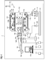
- FIG. 4 shows (including in particular the technical background) a (in a shielded room or Faraday cage F befindliches) imaging magnetic resonance apparatus MRT 101 with a hollow cylinder 102 with a tubular space 103 in which a patient couch 104 with a body such as an object to be examined (eg Patients) 105 (with or without local coil arrangement 106) can be moved in the direction of the arrow z in order to generate images of the patient 105 by means of an imaging method.
- a local coil arrangement 106 is arranged on the patient 105, with which MR images of a partial area of the body 105 in the FoV can be generated in a local area (also called field of view or FoV).
- Signals of the local coil arrangement 106 can be evaluated by an evaluation device (168, 115, 117, 119, 120, 121, etc.) of the MRT 101 that can be connected to the local coil arrangement 106 via coaxial cable or by radio (167) etc. (eg converted into images, stored or displayed).
- a strong magnet (often a cryomagnet 107) in a measuring booth with a tunnel-shaped opening 103 here generates a static strong main magnetic field B 0 , which is eg 0.2 Tesla to 3 Tesla or even more.
- a body 105 to be examined is mounted on a patient couch 104 in a viewing area FoV (also called "Field Of View” or "field of view”) approximately homogeneous region of the main magnetic field B0.
- An excitation of the nuclear spins of atomic nuclei of the body 105 via magnetic high-frequency excitation pulses B1 (x, y, z, t) via a here as (eg multi-part 108a, 108b, 108c) body coil 108 very simplified illustrated high-frequency antenna (and / or if necessary, a local coil arrangement) are irradiated.
- High-frequency excitation pulses are generated, for example, by a pulse generation unit 109 which is controlled by a pulse sequence control unit 110. After being amplified by a high-frequency amplifier 111, they are sent to the high-frequency antenna 108.
- the high-frequency system shown here is only indicated schematically. It is also possible that more than one pulse generating unit 109, more than one high-frequency amplifier 111 and a plurality of high-frequency antennas 108 a, b, c are used in a magnetic resonance apparatus 101.
- the magnetic resonance device 101 has gradient coils 112x, 112y, 112z with which magnetic gradient fields B G (x, y, z, t) for selective slice excitation and for spatial coding of the measured signal are radiated during a measurement.
- the gradient coils 112x, 112y, 112z become is controlled by a gradient coil control unit 114 (and possibly via amplifiers Vx, Vy, Vz) which, like the pulse generation unit 109, is connected to the pulse sequence control unit 110.
- Signals emitted by the excited nuclear spins are received by the body coil 108 and / or at least one local coil arrangement 106, amplified by associated high-frequency preamplifiers 116 and further processed and digitized by a receiving unit 117.
- the recorded measurement data are digitized and stored as complex numerical values in a k-space matrix. From the k-space matrix occupied with values, a corresponding MR image can be reconstructed by means of a multi-dimensional Fourier transformation.
- the correct signal transmission is controlled by an upstream transceiver 118.
- An image processing unit 119 generates from the measurement data an image that is displayed to a user via an operating console 120 and / or stored in a memory unit 121.
- a central computer unit 122 controls the individual system components.
- a switching matrix (sometimes called RCCS) is installed between receiving antennas and receiver, for example. This routes the currently active receive channels (usually those that are currently in the field of view of the magnet) to the existing receivers. This makes it possible to connect more coil elements than receivers are present, since in a full-body coverage only the coils must be read, which are located in the FoV or in the homogeneity volume of the magnet.
- a local coil arrangement 106 is generally referred to, for example, an antenna system, which may consist of one or as an array coil of a plurality of antenna elements (esp. Coil elements), for example. These individual antenna elements are designed, for example, as loop antennas (loops), butterfly, flex coils or saddle coils.
- a local coil arrangement comprises, for example, coil elements, a preamplifier, further electronics (standing wave barriers, etc.), a housing, supports and usually a cable with plug, by means of which it is connected to the MRT system.
- a receiver 168 mounted on the system filters and digitizes a signal received by a local coil 106, for example by radio etc., and transmits the data of a digital signal processing device which usually derives an image or a spectrum from the data obtained by a measurement and for example for subsequent diagnosis by the user provides him and / or storage.
- FIG. 1-4 show some details of exemplary embodiments of the invention.
- unwanted patient movement during image acquisition can cause severe image artifacts.
- Such unwanted motion artifacts can also be caused by respiration in the chest or abdominal area. Therefore, it may be useful to detect the patient's breathing and to synchronize the (MRI) image acquisition with the respiration cycle. This can be particularly helpful for magnetic resonance imaging (MRI) because imaging (MRI) can take several minutes and not every patient can hold their breath for so long.
- MRI magnetic resonance imaging
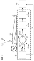
- Fig. 1 shows an embodiment of the invention with a placement here one or alternatively a plurality of RF resonators (resonant circuits) HF-Res in the vicinity of the patient 105 in the chest region BrB and / or abdominal region BaB.
- the RF resonator HF-Res (and / or the motion sensor AS with evaluation electronics) can be integrated into the patient couch 104 of a magnetic resonance tomography apparatus 101, for example.
- an RF signal from an RF generator (RF-Si-Srs) for example, via a coupling coil Cpl-In (or capacitive with eg a coupling capacitor or with other coupling) coupled.
- the RF signal generated in the HF generator RF-Si-Srs and coupled into the RF resonator HF-Res is coupled out again from the HF resonator (inductively or capacitively with, for example, a coupling capacitor or with a different coupling). out) and with the eg narrow-band RF detector (RF-Filt and / or HF-Dtect) filtered and detected.
- the eg narrow-band RF detector RF-Filt and / or HF-Dtect
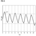
- WW Properties (WW, in this case in particular quality) of the RF resonator are influenced here by the respiration of the patient and thereby also changes the transmission (S21) of the RF signal via the RF resonator (ie the difference S21diff between S21-e in the patient who has inhaled compared to S21-a in the patient who has exhaled).
- This arrangement allows a measurement of the transmission losses of the RF resonator HF-Res, as in Fig. 1 is shown.
- the RF resonator HF-Res is constructed here so that the induced electromagnetic field RF-Si of the RF resonator HF-Res enters the body of the patient 105 so that an interaction WW between the RF resonator HF-Res and the body of the Patient 105 is enabled.
- a body movement AB (as well as a breathing movement or a displacement of the anatomy within the body, which could not be visible to the outside) then causes a change in the loaded quality of the RF resonator HF-Res.
- breathing movements AB of the patient 105 may be considered as in Fig. 3 shown temporal changes S21-diff of transmission S21-e-S21-a (before and after inhalation) over time t [s] are measured.
- the resonance frequency of the RF resonator HF-Res differs from the MR frequency of the magnetic resonance tomography device 101, so that little or as far as possible no mutual interference between the motion sensor or respiratory sensor AS and MR imaging arises can.
- the RF resonator HF-Res behaves e.g. as an inductive or capacitive sensor and not (or hardly) like an MRI imaging antenna (106) because of the inductive (or capacitive) near field. This minimizes radiated RF energy.
- Embodiments of the invention may be sensitive to respiration because the measured transmission losses of an RF resonator HF-Res depend on the air-tissue distribution;
- the muscle tissue can have large RF losses compared to the inhaled air.
- a transmission measurement does not require a directional coupler such as a measurement of the reflection factor and may be less sensitive to mismatches in a measurement path.
- Transmittance measurements according to the invention are feasible in a wide dynamic range and may be less ambiguous (zero crossing and sign change) than a measurement of the reflection factor.
- An HF resonator HF-Res can work similarly to an inductive sensor with negligible radiation, insofar as only the near field is necessary for the function.
- Embodiments of the invention may have a negligible impact on the SAR balance (as opposed to MR navigators) insofar as the used RF signals may have low power (eg, 1mW).
- a motion sensor AS can be integrated in a patient couch 104.
- the body distance can always be the same and in comparison with other methods, no new visible wiring will be necessary.
- the distance between a movement sensor AS and a patient 105 can be very constant in a motion sensor AS integrated in a patient couch 104, in particular in comparison to the alternative of placing the sensor above the patient behind the bore cover.
- Fig. 1 For example, an RF filter RF-Filt and an RF detector HF-Detect for detecting an RF signal are generally shown.
Landscapes
- Physics & Mathematics (AREA)
- Health & Medical Sciences (AREA)
- Life Sciences & Earth Sciences (AREA)
- Engineering & Computer Science (AREA)
- Condensed Matter Physics & Semiconductors (AREA)
- General Physics & Mathematics (AREA)
- Nuclear Medicine, Radiotherapy & Molecular Imaging (AREA)
- General Health & Medical Sciences (AREA)
- Radiology & Medical Imaging (AREA)
- High Energy & Nuclear Physics (AREA)
- Biophysics (AREA)
- Signal Processing (AREA)
- Physiology (AREA)
- Veterinary Medicine (AREA)
- Molecular Biology (AREA)
- Public Health (AREA)
- Pathology (AREA)
- Biomedical Technology (AREA)
- Heart & Thoracic Surgery (AREA)
- Medical Informatics (AREA)
- Animal Behavior & Ethology (AREA)
- Surgery (AREA)
- Vascular Medicine (AREA)
- Oral & Maxillofacial Surgery (AREA)
- Dentistry (AREA)
- Cardiology (AREA)
- Power Engineering (AREA)
- Pulmonology (AREA)
- Magnetic Resonance Imaging Apparatus (AREA)
Applications Claiming Priority (1)
| Application Number | Priority Date | Filing Date | Title |
|---|---|---|---|
| DE102015200510.0A DE102015200510A1 (de) | 2015-01-15 | 2015-01-15 | Bewegungssensor |
Publications (1)
| Publication Number | Publication Date |
|---|---|
| EP3045929A1 true EP3045929A1 (fr) | 2016-07-20 |
Family
ID=54936789
Family Applications (1)
| Application Number | Title | Priority Date | Filing Date |
|---|---|---|---|
| EP15199836.6A Withdrawn EP3045929A1 (fr) | 2015-01-15 | 2015-12-14 | Detecteur pour détecter des mouvements d'un patient dans un système d'imagerie |
Country Status (5)
| Country | Link |
|---|---|
| US (1) | US20160209486A1 (fr) |
| EP (1) | EP3045929A1 (fr) |
| JP (1) | JP2016131880A (fr) |
| CN (1) | CN105796104A (fr) |
| DE (1) | DE102015200510A1 (fr) |
Families Citing this family (7)
| Publication number | Priority date | Publication date | Assignee | Title |
|---|---|---|---|---|
| US10264200B2 (en) * | 2016-12-23 | 2019-04-16 | Omnivision Technologies, Inc. | Random sampling for horizontal noise reduction |
| EP3486672A1 (fr) * | 2017-11-16 | 2019-05-22 | Koninklijke Philips N.V. | Système d'imagerie par résonance magnétique doté de détection de mouvement rf |
| AU2019405138A1 (en) | 2018-12-19 | 2021-06-17 | Hyperfine Operations, Inc. | System and methods for grounding patients during magnetic resonance imaging |
| US12226201B2 (en) * | 2019-08-26 | 2025-02-18 | GE Precision Healthcare LLC | MRI system comprising patient motion sensor and signal processing method |
| US11419516B2 (en) * | 2019-08-26 | 2022-08-23 | GE Precision Healthcare LLC | MRI system comprising patient motion sensor |
| EP4575540A3 (fr) * | 2019-10-08 | 2025-09-03 | Hyperfine Operations, Inc. | Système et procédés de détection d'interférence électromagnétique chez des patients pendant une imagerie par résonance magnétique |
| WO2021081191A1 (fr) * | 2019-10-25 | 2021-04-29 | Hyperfine Research, Inc. | Systèmes et procédés de détection de mouvement de patient pendant une imagerie par résonance magnétique |
Citations (8)
| Publication number | Priority date | Publication date | Assignee | Title |
|---|---|---|---|---|
| EP0186238A2 (fr) * | 1984-12-21 | 1986-07-02 | Philips Patentverwaltung GmbH | Procédé de production d'un signal de déplacement et tomographe de spins nucléaires pour un tel procédé |
| DE4238831A1 (de) * | 1992-11-17 | 1994-05-19 | Siemens Ag | Hochfrequenzeinrichtung einer Anlage zur Kernspintomographie mit einer Oberflächenspule |
| US5575287A (en) * | 1993-01-25 | 1996-11-19 | Fonar Corporation | Inductively coupled RF coils for magnetic resonance studies |
| US6023166A (en) * | 1997-11-19 | 2000-02-08 | Fonar Corporation | MRI antenna |
| WO2011033422A1 (fr) * | 2009-09-17 | 2011-03-24 | Koninklijke Philips Electronics N.V. | Système d'imagerie par résonance magnétique comprenant des capteurs physiologiques |
| DE102009052412A1 (de) | 2009-10-02 | 2011-04-07 | Universität Duisburg-Essen | Meßsystem zur Erfassung der Lage eines sich bewegenden Organs |
| WO2013190451A1 (fr) * | 2012-06-21 | 2013-12-27 | Koninklijke Philips N.V. | Système d'examen par résonance magnétique à détection de mouvement |
| DE102014209488A1 (de) | 2014-05-20 | 2015-11-26 | Siemens Aktiengesellschaft | Verfahren zur Vermessung des Atemvorgangs eines Patienten während einer Magnetresonanzuntersuchung, Messanordnung und Magnetresonanzeinrichtung |
Family Cites Families (6)
| Publication number | Priority date | Publication date | Assignee | Title |
|---|---|---|---|---|
| JP2010522009A (ja) * | 2007-03-20 | 2010-07-01 | コーニンクレッカ フィリップス エレクトロニクス エヌ ヴィ | 磁気共鳴撮像システム及び方法 |
| DE102009019896A1 (de) * | 2009-05-04 | 2010-11-18 | Siemens Aktiengesellschaft | Vorrichtung zur Erfassung von Herzbewegungen in einem diagnostischen Magnetresonanzgerät |
| DE102009048150A1 (de) * | 2009-10-02 | 2011-04-07 | Siemens Aktiengesellschaft | Beschleuniger und Verfahren zur Ansteuerung eines Beschleunigers |
| EP2578148A1 (fr) * | 2011-10-04 | 2013-04-10 | Koninklijke Philips Electronics N.V. | Système d'imagerie médicale doté d'une détection des mouvements |
| JP2013228226A (ja) * | 2012-04-24 | 2013-11-07 | Toshiba Corp | Pet−mri装置 |
| CN104248436A (zh) | 2013-06-26 | 2014-12-31 | 西门子公司 | 采集呼吸周期 |
-
2015
- 2015-01-15 DE DE102015200510.0A patent/DE102015200510A1/de not_active Withdrawn
- 2015-12-14 EP EP15199836.6A patent/EP3045929A1/fr not_active Withdrawn
-
2016
- 2016-01-12 JP JP2016003376A patent/JP2016131880A/ja active Pending
- 2016-01-14 US US14/995,408 patent/US20160209486A1/en not_active Abandoned
- 2016-01-14 CN CN201610023557.6A patent/CN105796104A/zh active Pending
Patent Citations (8)
| Publication number | Priority date | Publication date | Assignee | Title |
|---|---|---|---|---|
| EP0186238A2 (fr) * | 1984-12-21 | 1986-07-02 | Philips Patentverwaltung GmbH | Procédé de production d'un signal de déplacement et tomographe de spins nucléaires pour un tel procédé |
| DE4238831A1 (de) * | 1992-11-17 | 1994-05-19 | Siemens Ag | Hochfrequenzeinrichtung einer Anlage zur Kernspintomographie mit einer Oberflächenspule |
| US5575287A (en) * | 1993-01-25 | 1996-11-19 | Fonar Corporation | Inductively coupled RF coils for magnetic resonance studies |
| US6023166A (en) * | 1997-11-19 | 2000-02-08 | Fonar Corporation | MRI antenna |
| WO2011033422A1 (fr) * | 2009-09-17 | 2011-03-24 | Koninklijke Philips Electronics N.V. | Système d'imagerie par résonance magnétique comprenant des capteurs physiologiques |
| DE102009052412A1 (de) | 2009-10-02 | 2011-04-07 | Universität Duisburg-Essen | Meßsystem zur Erfassung der Lage eines sich bewegenden Organs |
| WO2013190451A1 (fr) * | 2012-06-21 | 2013-12-27 | Koninklijke Philips N.V. | Système d'examen par résonance magnétique à détection de mouvement |
| DE102014209488A1 (de) | 2014-05-20 | 2015-11-26 | Siemens Aktiengesellschaft | Verfahren zur Vermessung des Atemvorgangs eines Patienten während einer Magnetresonanzuntersuchung, Messanordnung und Magnetresonanzeinrichtung |
Non-Patent Citations (1)
| Title |
|---|
| BUIKMAN; HELZEL; RÖSCHMANN, THE COIL AS A SENSITIVE MOTION DETECTOR FOR MRI-MAGNETIC-RESONANCE-IMAGING, vol. 6, no. 3, 1988 |
Also Published As
| Publication number | Publication date |
|---|---|
| US20160209486A1 (en) | 2016-07-21 |
| JP2016131880A (ja) | 2016-07-25 |
| DE102015200510A1 (de) | 2016-07-21 |
| CN105796104A (zh) | 2016-07-27 |
Similar Documents
| Publication | Publication Date | Title |
|---|---|---|
| DE102012211147B4 (de) | Automatische Verstimmung nicht angeschlossener Sende-Empfangsspulen für MRI | |
| EP3045929A1 (fr) | Detecteur pour détecter des mouvements d'un patient dans un système d'imagerie | |
| DE102012207722B3 (de) | MR- Antenne mit Kompensation für variablen Abstand zum Schirm | |
| DE102012206066A1 (de) | Erkennung ungesteckter Lokalspulen in einem Kernspintomographen | |
| DE102010004514A1 (de) | Dynamische Nachführung der HF-Justage bei parallelem Senden | |
| DE102012215004A1 (de) | Erkennung der statischen Position von Sende-/Empfangsspulen eines Magnetresonanztomographen mit Hilfe von elektronisch lesbaren Etiketten | |
| DE102012200600A1 (de) | MRT- Lokalspulenpositions-Erkennung in einem MRT-System | |
| DE102011079564B4 (de) | MRT Lokalspule | |
| DE102010004515A1 (de) | Wirbelsäulenspulenanordnung (spine coil array) für MRI Anwendungen mit verbesserten Bildgebungsmöglichkeiten für dedizierte Körperregionen | |
| DE102012215007A1 (de) | Erkennung der Position von Sende-/Empfangsspulen eines Magnetresonanztomographen mit Hilfe von in Bewegung gelesenen Etiketten | |
| DE102013217555B3 (de) | Kombinierte Shim- und HF-Spulenelemente | |
| DE102012204527B4 (de) | Mehrlagiges Kissen zur optimalen Anpassung an Anatomie und zur Suszeptibilitäts- Anpassung | |
| DE102012208325A1 (de) | Automatische Positionierung und Adaption in einem Justierungs-Verfahren für eine Shim- Feld- Karte basierend auf AutoAlign- und AutoCoverage | |
| DE102014210657A1 (de) | Achsen-verschiebbare Lokalspule | |
| DE102012215006A1 (de) | Erkennung von Sende-/Empfangsspulen eines Magnetresonanztomographen mit Hilfe von elektronisch lesbaren Etiketten | |
| DE102014207843B4 (de) | Knie-Spule | |
| DE102010004664B4 (de) | Flusssensor für Kühlwasser in einer Gradientenspule | |
| DE102014223878A1 (de) | Phasenüberwachung für mehrkanalige MR-Sendesysteme | |
| DE102009019896A1 (de) | Vorrichtung zur Erfassung von Herzbewegungen in einem diagnostischen Magnetresonanzgerät | |
| DE102013214130A1 (de) | Brustspule mit mechanischer Höhenverstellung | |
| DE102013217012B4 (de) | Lokal-SAR-Reduzierung für z.B. Patienten mit metallischen Implantaten | |
| DE102014215531B4 (de) | MRT und Verfahren zum Betrieb eines klinischen pTX-Systems | |
| DE102013213907A1 (de) | Automatische Lokalspulen-Isozentrierung | |
| DE102010063724B4 (de) | Lokalspule und Verfahren zum Verändern des Innendurchmessers einer Lokalspule | |
| DE102014202716A1 (de) | Verbesserung des lokalen SAR-Verhaltens von MRT-Sendespulen durch Verwendung orthogonaler Schleifenantennen |
Legal Events
| Date | Code | Title | Description |
|---|---|---|---|
| PUAI | Public reference made under article 153(3) epc to a published international application that has entered the european phase |
Free format text: ORIGINAL CODE: 0009012 |
|
| AK | Designated contracting states |
Kind code of ref document: A1 Designated state(s): AL AT BE BG CH CY CZ DE DK EE ES FI FR GB GR HR HU IE IS IT LI LT LU LV MC MK MT NL NO PL PT RO RS SE SI SK SM TR |
|
| AX | Request for extension of the european patent |
Extension state: BA ME |
|
| STAA | Information on the status of an ep patent application or granted ep patent |
Free format text: STATUS: THE APPLICATION IS DEEMED TO BE WITHDRAWN |
|
| 18D | Application deemed to be withdrawn |
Effective date: 20170121 |