EP3045930A1 - Testsystem für gegenseitige elektronische gis-induktoren und verfahren dafür - Google Patents
Testsystem für gegenseitige elektronische gis-induktoren und verfahren dafür Download PDFInfo
- Publication number
- EP3045930A1 EP3045930A1 EP14842552.3A EP14842552A EP3045930A1 EP 3045930 A1 EP3045930 A1 EP 3045930A1 EP 14842552 A EP14842552 A EP 14842552A EP 3045930 A1 EP3045930 A1 EP 3045930A1
- Authority
- EP
- European Patent Office
- Prior art keywords
- isolating switch
- voltage
- electronic instrument
- test system
- test
- Prior art date
- Legal status (The legal status is an assumption and is not a legal conclusion. Google has not performed a legal analysis and makes no representation as to the accuracy of the status listed.)
- Granted
Links
Images



Classifications
-
- G—PHYSICS
- G01—MEASURING; TESTING
- G01R—MEASURING ELECTRIC VARIABLES; MEASURING MAGNETIC VARIABLES
- G01R31/00—Arrangements for testing electric properties; Arrangements for locating electric faults; Arrangements for electrical testing characterised by what is being tested not provided for elsewhere
- G01R31/327—Testing of circuit interrupters, switches or circuit-breakers
- G01R31/3271—Testing of circuit interrupters, switches or circuit-breakers of high voltage or medium voltage devices
- G01R31/3272—Apparatus, systems or circuits therefor
- G01R31/3274—Details related to measuring, e.g. sensing, displaying or computing; Measuring of variables related to the contact pieces, e.g. wear, position or resistance
-
- G—PHYSICS
- G01—MEASURING; TESTING
- G01R—MEASURING ELECTRIC VARIABLES; MEASURING MAGNETIC VARIABLES
- G01R31/00—Arrangements for testing electric properties; Arrangements for locating electric faults; Arrangements for electrical testing characterised by what is being tested not provided for elsewhere
- G01R31/50—Testing of electric apparatus, lines, cables or components for short-circuits, continuity, leakage current or incorrect line connections
- G01R31/62—Testing of transformers
Definitions
- the present invention relates to a GIS electronic instrument transformer test system and a method thereof, and in particular to a GIS electronic instrument transformer test system based on opening-closing small capacity current of an isolating switch and a test method thereof.
- Electromagnetic interference is one of the important factors that affect the reliability and the stability of the electronic instrument transformers.
- the main reason why the electronic instrument transformers are interfered easily is that the equipment of the electronic instrument transformers is closer to a primary circuit, under the conditions of switch operation and system short circuit, the electronic instrument transformers are more vulnerable to interference by direct conduction and electromagnetic field coupling, and the layout, merging units and power supply modules thereof are liable to generate interference through electromagnetic radiation or ground potential rise.
- the intensity of the interference is far more than the current interference level regulated by the current electromagnetic compatibility standards, and this is also the main reason why the current electronic instrument transformers have passed electromagnetic compatibility tests but suffer electromagnetic protection faults on site.
- the objective of the present invention is to provide a GIS electronic instrument transformer test system based on opening-closing small capacity current of an isolating switch, so that various electromagnetic radiation of the system can be simulated to propose an electromagnetic compatibility test method meeting onsite electromagnetic protection requirements, in order to improve the protection performance of an electronic instrument transformer and reduce the fault rate of electromagnetic protection.
- the present invention adopts the following technical solutions:
- a second isolating switch is further arranged between said first to-be-tested electronic instrument transformer and said second to-be-tested electronic voltage transformer.
- the length of said GIS pipeline is adjustable
- a slide rail for expanding and contracting the GIS pipeline is arranged at a bottom of the power supply casing, and the slide rail can slide left and right.
- numerical values of small capacity current of opening-closing of the first and second isolating switches are 0.1-0.8A.
- the output current of the high voltage test transformer is 2A; and the first and second isolating switches are provided with electric operating mechanisms and AC 220V operating power supplies.
- a control cabinet is installed near the GIS pipeline, and the secondary converter and the merging unit are placed in the control cabinet.
- the primary transient current test system includes a primary transient current sensor
- the primary transient voltage test system includes a primary transient voltage sensor, a high speed collection card and a measurement upper computer
- the high speed collection card 3 respectively collects the outputs of the primary transient current sensor and the primary transient voltage sensor and transmits the outputs to the measurement upper computer in a data transmission mode.
- the primary transient voltage sensor is a hand hole type voltage sensor
- the hand hole type voltage sensor includes an induction electrode installed in a GIS hand hole, a hand hole cover plate and an insulating film located between the induction electrode and the hand hole cover plate, a layer of the insulating film is clamped between the induction electrode and the hand hole cover plate to form low voltage arm capacitance of the voltage divider, high voltage arm capacitance is formed between the induction electrode and a high voltage bus to constitute the capacitive voltage divider, so as to measure a transient overvoltage between the high voltage bus and a GIS housing;
- the primary transient current sensor adopts a hollow coil, and the hollow coil sleeves a current measurement site of the high voltage bus for measurement; and a shielding box is installed at a GIS pull opening, and the high speed collection card, a triggering system, an optical fiber control system and a power supply of the test system are placed in the shielding box.
- a test method of the GIS electronic instrument transformer test system based on the opening-closing small capacity current of the isolating switch includes the following steps:
- the method further includes the following steps:
- the GIS electronic instrument transformer test system based on the opening-closing small capacity current of the isolating switch in the present invention, when the isolating switch is opened and closed, a voltage value and a current valve of the high voltage bus in the GIS pipeline are tested to compare with the output of a product to be tested.
- 110KV, 220KV and 500KV test circuits for the opening-closing small capacity current of the isolating switch can be established in a lab, meanwhile, the electronic instrument transformer is serially connected to the test circuit to simulate load processes of opening-closing empty conducting wires and small capacity current of the isolating switch onsite, in order to generate similar onsite transient strong interference to check the electromagnetic protection performance of the electronic instrument transformer under the condition.
- the test platform can be applied to electromagnetic environments of 110KV, 220KV and 500KV voltage levels in power transmission and outage processes.
- An electromagnetic environment of a substation mainly includes an isolating switch and a strong electromagnetic interference phenomenon generated in the substation under circuit breaker operation, lightning, system short circuit and other conditions.
- a lightning impulse test carried out in a lab is used as a test method for checking the anti-electromagnetic interference ability of an electronic instrument transformer, but considering the energy of an artificial lightning impulse test and the entire test layout condition, the lightning impulse test carried out in the lab has relatively large difference with the real condition of discharging along a lightning conductor in the substation, and firstly, lightning current amplitude and energy simulated under artificial conditions are significantly weaker than those under actual conditions; and secondly, in the artificial test, the layout of test equipment is inconsistent with the actual conditions obviously. Therefore, the artificial lightning test cannot fully simulate actual onsite conditions, and thus the test result is not too good.
- An artificial ground test carried out in the lab also has similar problems, the biggest defect thereof is that the conditions of artificially simulated short circuit current have large difference with the actual conditions, and the amplitude and the duration thereof and the like are obviously weaker than those under the actual conditions, therefore the check of the anti-electromagnetic interference ability of the electronic instrument transformer under artificial ground test conditions are insufficient as well. If a 1: 1 true artificial ground test is carried out on the substation, better test conditions can be provided to check the electronic instrument transformer, but the danger of the test is large, and strong interference is generated on most weak current equipment in the substation. The test may cause unnecessary losses or retain hidden trouble to generate certain danger to the subsequent normal operation of the substation, and thus similar tests are scarcely carried out in a power system.
- the isolating switch interference source is a high-intensity interference source. If used in an electromagnetic compatibility test for checking the electronic instrument transformer, the isolating switch interference source can be used for checking the electromagnetic protection performance of the electronic instrument transformer to the uttermost.
- the isolating switch In a capacitor opening and closing process, the isolating switch generates an arc breakdown-extinguishment transient process for multiple times in a primary test circuit, pulse current, a transient overvoltage and a pulse electromagnetic field will be generated in the transient process for multiple times, numerical values of primary voltage and current are measured and recorded by standard voltage and standard current sensors in the primary circuit, an output value processed by a merging unit of the tested electronic instrument transformer is recorded at the same time, and the measured numerical values of the primary voltage and current waveforms are compared with the output properties of the tested electronic instrument transformer and the working state of the electronic instrument transformer in the entire test process is observed so as to judge the anti-electromagnetic interference ability of the tested electronic instrument transformer.
- a GIS electronic instrument transformer test system is introduced.
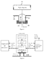
- Fig.1 to Fig.3 they are respectively an installation size diagram, a test circuit diagram and a test layout diagram of the 220KV GIS pipeline according to the present invention.
- the GIS electronic instrument transformer test system includes two BSG casings, a GIS pipeline is arranged between the two BSG casings, one casing is a power supply casing 105, the power supply casing is connected with a high voltage test transformer U1 and a capacitive voltage divider C1 used for protecting a power supply, which are connected in parallel each other, the capacitive voltage divider C1 is used for reducing a resonance effect caused by higher power supply impedance, the other casing is a load casing 106, the load casing is connected with a load capacitor C2, and since all GIS electronic instrument transformers belong to products with relatively small capacitance and based on the capacitive voltage division principle, the load capacitor C2 needs to be added to better simulate the actual conditions.
- the load capacitor C2 is conducive to stabilizing bus charging current, and the error is +/-10%.
- a first isolating switch DS1 is arranged in the GIS pipeline close to the power supply casing, and a first calibration primary transient test system 101, a first to-be-tested electronic instrument transformer 102, a second to-be-tested electronic voltage transformer 103 and a second calibration primary transient voltage test system 104 are arranged between the first isolating switch DS1 and the load casing.
- the first to-be-tested electronic instrument transformer 102 is close to the first isolating switch DS1
- the second to-be-tested electronic voltage transformer 103 is close to the load casing
- the first to-be-tested electronic instrument transformer 102 is an electronic current transformer ECT or an electronic current and voltage combined transformer ECVT
- the reason why the second to-be-tested electronic voltage transformer EVT is arranged is that the influence of a distance away from the isolating switch on the transient voltage is relatively large
- the second to-be-tested electronic voltage transformer is additionally arranged between the first to-be-tested electronic instrument transformer and the load casing.
- One end of a secondary converter 110 is connected with the to-be-tested electronic instrument transformers 102 and 103, the other end of the secondary converter is connected with a merging unit 111, the other end of the merging unit 111 is connected with a fault recorder 112, and the fault recorder 112 is used for connecting the output of the merging unit 111.
- the first calibration primary transient test system 101 is arranged near the first to-be-tested electronic instrument transformer 102 and is a primary transient current test system corresponding to the first to-be-tested electronic instrument transformer or a combination of primary transient voltage and current test systems.
- the second calibration primary transient voltage test system 104 is arranged near the second to-be-tested electronic voltage transformer 103 and is a primary transient voltage test system corresponding to the second to-be-tested electronic voltage transformer.
- the to-be-tested electronic instrument transformer can be located at different positions in the pipeline, and thus the transient voltage or current at different positions away from the first isolating switch DS1 can be simulated.
- the to-be-tested electronic instrument transformers 102 and 103 are located on a load side, namely located between the first isolating switch DS1 and the load casing, and only the distances away from the isolating switch are different, and thus the influence of the length of the pipeline on the transient voltage and the transient current on the load side can be researched.
- the length of the GIS pipeline is adjustable
- a slide rail for expanding and contracting the GIS pipeline is arranged at a bottom of the power supply casing 105 and can slide left and right, so that different GIS pipelines can be simulated, which is further conducive to searching the influence of lengths of the different GIS pipelines on the transient voltage and the transient current on the load side.
- the adjustable length of the GIS pipeline and the telescopic slide rail can be compatible to samples of electronic instrument transformers from different manufacture companies.
- an auxiliary second isolating switch DS2 is further arranged between the first to-be-tested electronic instrument transformer and the second to-be-tested electronic voltage transformer, in this way, the test ability of the current is expanded, and thus the test circuit can be used for researching transient parameters in the following two manners:
- the power supply is placed on the right side, the load is placed on the left side, the DS1 is normally closed, the DS2 is opened, the data tested by the two transient test systems are respectively transient voltage waveforms of the load side (between the isolating switch and the load) and the power supply side (between the isolating switch and the power supply), and thus the difference of the transient voltages of the load side and the power supply side can be researched.
- the positions of the to-be-tested electronic instrument transformers in the GIS pipeline are not fixed and the to-be-tested electronic instrument transformers can be located at different positions in the pipeline, so that the transient voltage or current at different positions away from the first isolating switch DS1 can be simulated.
- ES represents a ground switch
- DS represents an isolating switch
- EVT represents a test sample of an electronic voltage transformer
- ECT represents a test sample of an electronic current transformer
- ECVT represents a test sample of an electronic current and voltage combined transformer.
- One EVT can be connected to a position 2 and the ECT or the ECVT can be installed at a position 3 of the test platform at the same time.
- a primary transient voltage sensor is respectively placed at each of a position 1 and a position 4, and a primary transient current sensor is placed at the position 4.
- the first calibration primary transient current and voltage test system, the first to-be-tested electronic combined current and voltage transformer, the second isolating switch, the second to-be-tested electronic voltage transformer and the second calibration primary transient voltage test system are installed between the first isolating switch DS1 and the load casing in sequence.
- the to-be-tested electronic instrument transformers and the primary transient test systems can set the to-be-tested electronic instrument transformers and the primary transient test systems at different positions of the pipeline in different voltage levels, as long as the to-be-tested electronic current transformer or the to-be-tested electronic current and voltage combined transformer is arranged at the position close to the power supply casing, the to-be-tested electronic voltage transformer is additionally arranged near the load casing, and the corresponding calibration primary transient test systems are arranged respectively.
- the output current of the high voltage test transformer 101 is 2A; and the GIS first isolating switch DS1 and the GIS second isolating switch DS2 are provided with electric operating mechanisms and AC 220V operating power supplies.
- a control cabinet is installed near the GIS pipeline, the secondary converter 110 and the merging unit 110 of the to-be-tested electronic instrument transformer are placed in the control cabinet, the power supply of the control cabinet is DC 220KV, and the control cabinet is powered by a DC screen.
- the steady state voltage thereof changes, and the power supply change thereof should be not larger than +/-10% according to the requirements of GB1985-2004 "high voltage AC isolating switch and ground switch".
- a primary part, a secondary connection and the electronic merging unit of the tested electronic instrument transformer are completely assembled and connected according to actual use conditions, and the electronic instrument transformer is powered and operates according to normal working conditions in the test process.
- Opening-closing small capacity current of an isolating switch is used for testing the electromagnetic compatibility of an electronic instrument transformer, and the basic principle is to test the electromagnetic compatibility of the electronic instrument transformer under a condition of generating strong electromagnetic interference, therefore a strong electromagnetic interference condition parameter is one of the important parameters of the test.
- Main parameters in the process of the opening-closing small capacity current of the isolating switch include: voltage, current, an electric field, a magnetic field and housing potential rise. Wherein, the voltage and the current are the most important parameters, and thus measurement of the voltage and the current is the critical step for testing the immunity to interference of the electronic instrument transformer under the condition of the opening-closing small capacity current of the isolating switch.
- the first calibration primary transient current and voltage test system and the second calibration primary transient voltage test system are included, wherein the first calibration primary transient current and voltage test system 101 includes a primary transient current sensor, a primary transient voltage sensor, a high speed collection card 113 and a measurement upper computer 114, the high speed collection card 113 respectively collects the outputs of the primary transient current sensor and the primary transient voltage sensor and transmits the outputs to the measurement upper computer 114 in a data transmission mode, for example, photovoltaic conversion, to carry out subsequent data processing.
- a data transmission mode for example, photovoltaic conversion
- the second calibration primary transient voltage test system 104 includes a primary transient voltage sensor, and the high speed collection card 113 collects the output of the primary transient voltage sensor and transmits the output to the measurement upper computer 114 in the data transmission mode, for example, photovoltaic conversion, to carry out subsequent data processing.
- the high speed collection card 113 is powered by laser power supply, battery or solar power supply.
- the measurement upper computer can adopt any available calculating device, such as an industrial control computer, a notebook computer and a PC.
- the test system includes a corresponding standard sensor, and the high speed collection card 113 collects the output of the standard sensor and transmits the output to the measurement upper computer 114 in the data transmission mode, for example, photovoltaic conversion, to carry out subsequent data processing.
- a control cabinet is installed near the GIS pipeline, and a secondary converter and a merging unit of the to-be-tested electronic instrument transformer are placed in the control cabinet.
- the high speed collection card and a battery power supply module of the transient test system are placed in a shielding box on the outer wall of the GIS pipeline.
- a notebook computer upper computer and a fault recorder are placed in a personnel operating room.
- a transient electromagnetic process of an operation of the isolating switch is a very complex process, has the features of a wide bandwidth (50Hz to 100MHz) and a long duration (several seconds), and has higher requirements on the measurement frequency bands, the anti-interference performance and the length of recorded data of a pre-probe and a measurement system, and thus "professional measurement” is required in related standards.
- the calibration primary transient voltage sensor is a hand hole type voltage sensor.
- the hand hole type voltage sensor includes an induction electrode 202 installed in a GIS hand hole 205, a hand hole cover plate 204 and an insulating film 203 located between the induction electrode and the hand hole cover plate, wherein the insulating film can be a plastic film.
- a layer of the insulating film 203 is clamped between the induction electrode 202 and the hand hole cover plate 204 to form low voltage arm capacitance of a voltage divider, high voltage arm capacitance is formed between the induction electrode 202 and a high voltage bus 201 to constitute the capacitive voltage divider, so as to measure a transient overvoltage between the high voltage bus in GIS and a GIS housing.
- FIG.5 an installation structure diagram of a primary transient voltage sensor of a GIS pipeline is disclosed exemplarily.
- a shielding box 301 is independently installed at the outside of the hand hole 205, an oscilloscope type high speed collection card 113, a triggering system (not shown in the figure), an optical fiber control system (not shown in the figure) and a power supply of the test system are placed in the shielding box 301, and the shielding box 301 is directly installed on a pull opening of GIS to prevent the influence of radiated electromagnetic interference and conducted electromagnetic interference on the measurement system.
- the power supply includes a storage battery 302 and an inverter power supply 303.
- the GIS calibration primary transient current sensor adopts a hollow coil, and the hollow coil sleeves a current measurement site of the high voltage bus for measurement.
- Fig.6 it is an installation structure diagram of a primary transient current sensor of a GIS pipeline based on an embodiment of the present invention, the hollow coil outputs to the oscilloscope type high speed collection card 113 for measurement, similarly, the shielding box 301 is independently installed at the outside of the hand hole, the oscilloscope type high speed collection card 113, the triggering system (not shown in the figure), the optical fiber control system (not shown in the figure) and the power supply of the test system are placed in the shielding box 301, and the shielding box 301 is directly installed on a pull opening of GIS to prevent the influence of radiated electromagnetic interference and conducted electromagnetic interference on the measurement system.
- the power supply includes the storage battery 302 and the inverter power supply 303.
- high voltage arm capacitance can be determined according to determined voltage division ratio of a capacitive sensor and low voltage arm capacitance.
- a GIS structural size, a hand hole diameter, an electrode diameter and a thickness are given, and a hand hole depth is selected to obtain the required high voltage arm capacitance.
- coupling capacitance among multiple conductors can be calculated, and the designed size of the GIS hand hole is determined according to the necessary high voltage arm capacitance.
- the test method includes the following steps:
- the data tested by two transient voltage test systems are transient voltage waveforms of the load side (between the isolating switch and the load), and only the distances away from the isolating switch are different.
- the method further includes the following steps:
- test samples are not damaged; communication interruption, packet loss, quality change of the merging unit do not occur; and output abnormality of the merging unit is not allowed (single-point output of the output abnormality exceeds 100% of rated secondary output or the output of two continuous points exceeds 40% of the rated secondary output).
- the GIS electronic instrument transformer test system based on the opening-closing small capacity current of the isolating switch in the present invention, when the isolating switch is opened and closed, a voltage value and a current valve of the high voltage bus are tested to compare with the output of a product to be tested.
- the present invention is beneficial to solving the electromagnetic compatibility problem of the primary circuit and improving the electromagnetic compatibility protection measures. Meanwhile, a design of standard high frequency current and voltage sensors is further proposed.
- 110KV, 220KV and 500KV test circuits for the opening-closing small capacity current of the isolating switch can be established in a lab, meanwhile, the electronic instrument transformer is serially connected to the test circuit to simulate load processes of opening-closing empty conducting wires and small capacity current of the isolating switch onsite, in order to generate similar onsite transient strong interference to check the electromagnetic protection performance of the electronic instrument transformer under the condition.
- the test platform can be applied to electromagnetic environments in power transmission and outage processes of 110KV, 220KV and 500KV voltage levels.
Landscapes
- Engineering & Computer Science (AREA)
- Physics & Mathematics (AREA)
- General Physics & Mathematics (AREA)
- Theoretical Computer Science (AREA)
- Power Engineering (AREA)
- Testing Relating To Insulation (AREA)
- Testing Electric Properties And Detecting Electric Faults (AREA)
Applications Claiming Priority (2)
| Application Number | Priority Date | Filing Date | Title |
|---|---|---|---|
| CN201310407523.3A CN103487780B (zh) | 2013-09-09 | 2013-09-09 | 一种gis电子互感器测试系统及其方法 |
| PCT/CN2014/085982 WO2015032343A1 (zh) | 2013-09-09 | 2014-09-05 | 一种gis电子互感器测试系统及其方法 |
Publications (3)
| Publication Number | Publication Date |
|---|---|
| EP3045930A1 true EP3045930A1 (de) | 2016-07-20 |
| EP3045930A4 EP3045930A4 (de) | 2017-05-17 |
| EP3045930B1 EP3045930B1 (de) | 2018-05-16 |
Family
ID=49828150
Family Applications (1)
| Application Number | Title | Priority Date | Filing Date |
|---|---|---|---|
| EP14842552.3A Active EP3045930B1 (de) | 2013-09-09 | 2014-09-05 | Testsystem für gegenseitige elektronische gis-induktoren und verfahren dafür |
Country Status (4)
| Country | Link |
|---|---|
| EP (1) | EP3045930B1 (de) |
| CN (1) | CN103487780B (de) |
| CA (1) | CA2927519A1 (de) |
| WO (1) | WO2015032343A1 (de) |
Cited By (5)
| Publication number | Priority date | Publication date | Assignee | Title |
|---|---|---|---|---|
| CN106646320A (zh) * | 2016-10-09 | 2017-05-10 | 国网江苏省电力公司电力科学研究院 | 基于站内联合测量的电子式电流互感器异常辨识方法 |
| CN110888098A (zh) * | 2018-09-07 | 2020-03-17 | 中国电力科学研究院有限公司 | 一种电子式互感器的敏感部件的测试方法 |
| CN111273167A (zh) * | 2018-12-05 | 2020-06-12 | 西安高压电器研究院有限责任公司 | 一种隔离开关小感性电流开合试验电路 |
| CN112710978A (zh) * | 2020-11-30 | 2021-04-27 | 国网北京市电力公司 | 抗直流互感器的检测系统 |
| CN113625215A (zh) * | 2021-10-12 | 2021-11-09 | 国网江西省电力有限公司电力科学研究院 | 基于分段测试的电压互感器异常校准方法及装置 |
Families Citing this family (45)
| Publication number | Priority date | Publication date | Assignee | Title |
|---|---|---|---|---|
| CN103487780B (zh) * | 2013-09-09 | 2016-03-23 | 国家电网公司 | 一种gis电子互感器测试系统及其方法 |
| CN103969537B (zh) * | 2014-06-04 | 2017-08-25 | 贵州电力试验研究院 | 模拟量、数字量混合采集的互感器干扰源测试系统及方法 |
| CN104155626B (zh) * | 2014-08-15 | 2017-03-08 | 国家电网公司 | 一种检测电压互感器抵御地电位升高能力的系统 |
| CN104597425B (zh) * | 2015-01-21 | 2019-06-14 | 国家电网公司 | 一种适用于gis电子式互感器带电考核平台 |
| CN106443144A (zh) * | 2015-08-11 | 2017-02-22 | 中国电力科学研究院 | 一种特高压gis用分布式暂态过电压监测系统 |
| CN105137135B (zh) * | 2015-08-13 | 2018-04-17 | 国家电网公司 | 一种隔离开关模拟电磁骚扰源 |
| CN105353332B (zh) * | 2015-10-29 | 2023-11-14 | 中国电力科学研究院 | 一种电子式互感器长期带电性能考核方法及系统 |
| CN105301400A (zh) * | 2015-11-10 | 2016-02-03 | 中国电力科学研究院 | 一种特高压交流设备运行工况模拟系统 |
| CN106168658B (zh) * | 2016-08-31 | 2023-06-02 | 贵州电网有限责任公司 | 一种减小电压互感器二次压降的装置及方法 |
| CN106526435B (zh) * | 2016-10-17 | 2023-04-18 | 国网安徽省电力公司电力科学研究院 | 有源电子式电压互感器用电压转换器冲击测试装置及方法 |
| CN106680549A (zh) * | 2016-12-29 | 2017-05-17 | 国家电网公司 | 一种gis暂态模拟电磁骚扰源 |
| CN107271945B (zh) * | 2017-06-26 | 2020-05-12 | 国家电网公司 | 一种系统级电子式互感器电磁兼容试验系统及方法 |
| CN107490719A (zh) * | 2017-08-09 | 2017-12-19 | 国网山东省电力公司经济技术研究院 | Gis内基于罗氏线圈原理的电子式互感器 |
| CN107728096B (zh) * | 2017-09-28 | 2024-03-22 | 山东泰开互感器有限公司 | 一种电容式电压互感器试验系统 |
| CN107907848A (zh) * | 2017-10-27 | 2018-04-13 | 国网浙江省电力公司杭州供电公司 | 用于电子式互感器的检测方法 |
| CN108051769A (zh) * | 2017-12-12 | 2018-05-18 | 中国西电电气股份有限公司 | 一种电容式电压互感器暂态响应试验装置及试验方法 |
| CN108089082B (zh) * | 2018-01-16 | 2023-11-24 | 中国南方电网有限责任公司超高压输电公司曲靖局 | 高压直流中性母线避雷器性能在线监测系统及方法 |
| DE102018204076A1 (de) * | 2018-03-16 | 2019-09-19 | Siemens Aktiengesellschaft | Vorrichtung aufweisend einen Messwandler |
| CN109814060A (zh) * | 2019-01-03 | 2019-05-28 | 广西电网有限责任公司贵港供电局 | 多台高压电流互感器的检定系统及其方法 |
| CN110441575B (zh) * | 2019-05-28 | 2022-09-27 | 中国电力科学研究院有限公司 | 一种共箱型气体绝缘金属封闭开关设备gis电子式电压互感器 |
| CN110261808B (zh) * | 2019-06-10 | 2024-04-16 | 国网湖南省电力有限公司 | 一种车载gis式表源装置 |
| CN110161445B (zh) * | 2019-06-11 | 2024-03-08 | 沈阳仪表科学研究院有限公司 | 汽车电流传感器自动测试装置 |
| CN111650440B (zh) * | 2020-05-29 | 2025-01-21 | 国网上海市电力公司 | 一种gis回路电阻测量装置及方法 |
| CN111693926A (zh) * | 2020-07-20 | 2020-09-22 | 内蒙古电力(集团)有限责任公司内蒙古电力科学研究院分公司 | 一种电压互感器校验系统 |
| CN112051478B (zh) * | 2020-09-09 | 2025-07-22 | 国网电力科学研究院武汉南瑞有限责任公司 | 一种全自动高压电流互感器多功能测试装置 |
| CN114384830B (zh) * | 2020-10-20 | 2024-07-23 | 中国电力科学研究院有限公司 | 一种用于智能电网采集单元的电磁干扰确定方法及系统 |
| CN112485745A (zh) * | 2020-11-17 | 2021-03-12 | 广东电网有限责任公司计量中心 | 一种自带隔离开关的仿真平台 |
| CN112485717B (zh) * | 2020-12-05 | 2025-03-25 | 辽宁东科电力有限公司 | 配电真型试验负载模拟装置及方法 |
| CN112731210B (zh) * | 2020-12-09 | 2021-12-17 | 江苏核电有限公司 | 一种不拆高压侧gis的主变压器电气预防性试验方法 |
| CN112816930A (zh) * | 2020-12-31 | 2021-05-18 | 国家电网有限公司 | 一种用于确定电子式互感器辐射抗扰度的试验方法及系统 |
| CN113484592B (zh) * | 2021-04-25 | 2023-04-28 | 南方电网科学研究院有限责任公司 | 一种直流输电测量系统及其测量延时的测试方法 |
| CN113189386A (zh) * | 2021-05-11 | 2021-07-30 | 国网山东省电力公司泰安供电公司 | Gis快速暂态过电压光学在线监测系统 |
| CN113311373A (zh) * | 2021-06-24 | 2021-08-27 | 广东电网有限责任公司 | 一种直流电压互感器校验仪的校准方法及校准装置 |
| CN113466685B (zh) * | 2021-06-30 | 2024-05-14 | 国网陕西省电力有限公司电力科学研究院 | 一种微缩型gis电磁骚扰模拟试验装置及方法 |
| CN114019323A (zh) * | 2021-11-01 | 2022-02-08 | 国网陕西省电力公司电力科学研究院 | 一种同频同相交流耐压试验控制系统及方法 |
| CN113985271B (zh) * | 2021-11-04 | 2024-06-11 | 中铁武汉电气化局集团有限公司 | 地铁gis高压开关柜系统检测装置及方法 |
| CN114062752A (zh) * | 2021-11-18 | 2022-02-18 | 浙江天正电气股份有限公司 | 互感器处理方法和互感器与计量芯的一致性实现方法 |
| CN114389371A (zh) * | 2021-12-03 | 2022-04-22 | 中宝电气有限公司 | 一种电容式高压自取电电源和测量一体装置 |
| CN115308587A (zh) * | 2022-08-04 | 2022-11-08 | 德丰电创科技股份有限公司 | 一种器具开关测试方法及器具测试装置 |
| CN115308474A (zh) * | 2022-08-30 | 2022-11-08 | 国网新疆电力有限公司电力科学研究院 | 一种空载母线电流确定方法及应用其的母线分合控制方法 |
| CN116223957A (zh) * | 2023-03-15 | 2023-06-06 | 国网新疆电力有限公司电力科学研究院 | 一种故障分析检测系统及故障分析检测方法 |
| CN118226242B (zh) * | 2024-03-25 | 2024-12-31 | 国网江苏省电力有限公司南京供电分公司 | 隔离开关位置双确认方法、装置、电子设备及存储介质 |
| CN119087210B (zh) * | 2024-11-06 | 2025-04-01 | 上海万控柜架有限公司 | 一种配电柜断路器在线监测装置 |
| CN119511174B (zh) * | 2024-11-15 | 2025-07-04 | 中国电子技术标准化研究院 | 一种用于校准高功率大电流参数的测试系统及方法 |
| CN120490943B (zh) * | 2025-05-08 | 2025-12-23 | 国网湖北省电力有限公司荆州供电公司 | 一种用于电力互感器一体化试验的智能接口矩阵 |
Family Cites Families (9)
| Publication number | Priority date | Publication date | Assignee | Title |
|---|---|---|---|---|
| JPH0879965A (ja) * | 1994-09-05 | 1996-03-22 | Nissin Electric Co Ltd | ガス絶縁開閉装置の事故点標定方法 |
| CN101504432A (zh) * | 2009-01-24 | 2009-08-12 | 国网电力科学研究院 | 变电站暂态电磁场测量方法 |
| CN102087347B (zh) * | 2009-12-08 | 2013-05-29 | 张建 | 一种电流互感器的带电测试方法及其应用 |
| CN101881813B (zh) * | 2010-06-17 | 2013-12-04 | 国网电力科学研究院 | 模拟gis变电站中产生特快速瞬态过电压的方法及试验回路 |
| CN102043139B (zh) * | 2010-12-16 | 2013-03-27 | 中国人民解放军空军工程大学 | 电流互感器校验装置及采用该装置校验电流互感器的方法 |
| CN102565647B (zh) * | 2012-02-14 | 2015-04-29 | 重庆市电力公司电力科学研究院 | Gis耐压测试系统 |
| CN103257293B (zh) * | 2013-04-27 | 2015-09-02 | 国家电网公司 | 一种输电线路雷电电磁暂态动模实验系统 |
| CN103487780B (zh) * | 2013-09-09 | 2016-03-23 | 国家电网公司 | 一种gis电子互感器测试系统及其方法 |
| CN203502582U (zh) * | 2013-09-09 | 2014-03-26 | 国家电网公司 | 基于隔离开关分合容性小电流的gis电子互感器测试系统 |
-
2013
- 2013-09-09 CN CN201310407523.3A patent/CN103487780B/zh active Active
-
2014
- 2014-09-05 EP EP14842552.3A patent/EP3045930B1/de active Active
- 2014-09-05 CA CA2927519A patent/CA2927519A1/en not_active Abandoned
- 2014-09-05 WO PCT/CN2014/085982 patent/WO2015032343A1/zh not_active Ceased
Non-Patent Citations (1)
| Title |
|---|
| See references of WO2015032343A1 * |
Cited By (8)
| Publication number | Priority date | Publication date | Assignee | Title |
|---|---|---|---|---|
| CN106646320A (zh) * | 2016-10-09 | 2017-05-10 | 国网江苏省电力公司电力科学研究院 | 基于站内联合测量的电子式电流互感器异常辨识方法 |
| CN106646320B (zh) * | 2016-10-09 | 2019-06-11 | 国网江苏省电力公司电力科学研究院 | 基于站内联合测量的电子式电流互感器异常辨识方法 |
| CN110888098A (zh) * | 2018-09-07 | 2020-03-17 | 中国电力科学研究院有限公司 | 一种电子式互感器的敏感部件的测试方法 |
| CN111273167A (zh) * | 2018-12-05 | 2020-06-12 | 西安高压电器研究院有限责任公司 | 一种隔离开关小感性电流开合试验电路 |
| CN111273167B (zh) * | 2018-12-05 | 2022-06-03 | 西安高压电器研究院股份有限公司 | 一种隔离开关小感性电流开合试验电路 |
| CN112710978A (zh) * | 2020-11-30 | 2021-04-27 | 国网北京市电力公司 | 抗直流互感器的检测系统 |
| CN113625215A (zh) * | 2021-10-12 | 2021-11-09 | 国网江西省电力有限公司电力科学研究院 | 基于分段测试的电压互感器异常校准方法及装置 |
| CN113625215B (zh) * | 2021-10-12 | 2021-12-31 | 国网江西省电力有限公司电力科学研究院 | 基于分段测试的电压互感器异常校准方法及装置 |
Also Published As
| Publication number | Publication date |
|---|---|
| EP3045930A4 (de) | 2017-05-17 |
| CN103487780B (zh) | 2016-03-23 |
| EP3045930B1 (de) | 2018-05-16 |
| CA2927519A1 (en) | 2015-03-12 |
| CN103487780A (zh) | 2014-01-01 |
| WO2015032343A1 (zh) | 2015-03-12 |
Similar Documents
| Publication | Publication Date | Title |
|---|---|---|
| EP3045930B1 (de) | Testsystem für gegenseitige elektronische gis-induktoren und verfahren dafür | |
| CN103487679B (zh) | 一种ais电子互感器测试系统及其方法 | |
| CN103091609B (zh) | 一种gis局部放电在线监测装置性能检测系统及其方法 | |
| Cataliotti et al. | Oil-filled MV/LV power-transformer behavior in narrow-band power-line communication systems | |
| CN202854255U (zh) | 一种电容式电压互感器测试装置 | |
| CN101762799B (zh) | 一种电压互感器在线精度检测系统 | |
| CN103616574B (zh) | 一种电动汽车储能并网逆变器防孤岛检测系统及检测方法 | |
| CN100580464C (zh) | 发电厂、变电站大型接地网检测方法及其检测系统 | |
| CN203502582U (zh) | 基于隔离开关分合容性小电流的gis电子互感器测试系统 | |
| CN106094571B (zh) | 多功能防窃电仿真实验平台 | |
| Schöttke et al. | Transfer characteristic of a MV/LV transformer in the frequency range between 2 kHz and 150 kHz | |
| CN101504432A (zh) | 变电站暂态电磁场测量方法 | |
| CN203502581U (zh) | 基于隔离开关分合容性小电流的ais电子互感器测试系统 | |
| CN203396866U (zh) | 一种电动汽车储能并网逆变器防孤岛检测系统 | |
| CN204359883U (zh) | 一种变压器用多功能测试仪 | |
| CN116008856A (zh) | 基于频域分析的避雷器带电检测方法及装置 | |
| CN105353332A (zh) | 一种电子式互感器长期带电性能考核方法及系统 | |
| CN204177954U (zh) | 一种35kV高压电能计量装置整体误差检定系统 | |
| CN203324432U (zh) | 一种新型的高压容性电气设备绝缘在线监测系统 | |
| Yang et al. | Improving the polarisation and depolarisation current measuring method to avoid ground wire interference | |
| CN205176250U (zh) | 电子式互感器长期带电性能考核二次及一次接线系统 | |
| CN203535206U (zh) | Gis局部放电仿真系统 | |
| CN106772190A (zh) | 一种vfto条件下电子式电压互感器的测试比对方法及装置 | |
| Hailong et al. | Research on detection system for 10kV distribution switcher of both Primary and secondary technology | |
| Maslowski et al. | Surge current distribution in the lightning protection system of a test house equppied in electrical and electronic appliances |
Legal Events
| Date | Code | Title | Description |
|---|---|---|---|
| PUAI | Public reference made under article 153(3) epc to a published international application that has entered the european phase |
Free format text: ORIGINAL CODE: 0009012 |
|
| 17P | Request for examination filed |
Effective date: 20160407 |
|
| AK | Designated contracting states |
Kind code of ref document: A1 Designated state(s): AL AT BE BG CH CY CZ DE DK EE ES FI FR GB GR HR HU IE IS IT LI LT LU LV MC MK MT NL NO PL PT RO RS SE SI SK SM TR |
|
| AX | Request for extension of the european patent |
Extension state: BA ME |
|
| DAX | Request for extension of the european patent (deleted) | ||
| A4 | Supplementary search report drawn up and despatched |
Effective date: 20170418 |
|
| RIC1 | Information provided on ipc code assigned before grant |
Ipc: G01R 31/327 20060101ALI20170410BHEP Ipc: G01R 31/06 20060101ALI20170410BHEP Ipc: G01R 35/02 20060101AFI20170410BHEP |
|
| GRAP | Despatch of communication of intention to grant a patent |
Free format text: ORIGINAL CODE: EPIDOSNIGR1 |
|
| INTG | Intention to grant announced |
Effective date: 20171219 |
|
| RIN1 | Information on inventor provided before grant (corrected) |
Inventor name: HUANG, HUA Inventor name: LIU, XIANG Inventor name: WAN, GANG Inventor name: WANG, YINGYING Inventor name: DENG, XIAOPIN Inventor name: LIU, BIN Inventor name: WU, WENLIANG Inventor name: WANG, XIAOZHOU Inventor name: TONG, YUE Inventor name: LIU, YONG Inventor name: FENG, XIANGXIANG Inventor name: HU, BEI Inventor name: XIONG, JUNJUN Inventor name: WANG, YAN Inventor name: YANG, FAN Inventor name: GUO, KEQIN Inventor name: CHEN, PENG Inventor name: ZHANG, QIN Inventor name: DAI, JING Inventor name: YE, GUOXIONG |
|
| GRAS | Grant fee paid |
Free format text: ORIGINAL CODE: EPIDOSNIGR3 |
|
| GRAA | (expected) grant |
Free format text: ORIGINAL CODE: 0009210 |
|
| AK | Designated contracting states |
Kind code of ref document: B1 Designated state(s): AL AT BE BG CH CY CZ DE DK EE ES FI FR GB GR HR HU IE IS IT LI LT LU LV MC MK MT NL NO PL PT RO RS SE SI SK SM TR |
|
| REG | Reference to a national code |
Ref country code: GB Ref legal event code: FG4D |
|
| REG | Reference to a national code |
Ref country code: CH Ref legal event code: EP |
|
| REG | Reference to a national code |
Ref country code: IE Ref legal event code: FG4D |
|
| REG | Reference to a national code |
Ref country code: DE Ref legal event code: R096 Ref document number: 602014025701 Country of ref document: DE |
|
| REG | Reference to a national code |
Ref country code: AT Ref legal event code: REF Ref document number: 1000070 Country of ref document: AT Kind code of ref document: T Effective date: 20180615 |
|
| REG | Reference to a national code |
Ref country code: NL Ref legal event code: FP |
|
| REG | Reference to a national code |
Ref country code: LT Ref legal event code: MG4D |
|
| PG25 | Lapsed in a contracting state [announced via postgrant information from national office to epo] |
Ref country code: LT Free format text: LAPSE BECAUSE OF FAILURE TO SUBMIT A TRANSLATION OF THE DESCRIPTION OR TO PAY THE FEE WITHIN THE PRESCRIBED TIME-LIMIT Effective date: 20180516 Ref country code: ES Free format text: LAPSE BECAUSE OF FAILURE TO SUBMIT A TRANSLATION OF THE DESCRIPTION OR TO PAY THE FEE WITHIN THE PRESCRIBED TIME-LIMIT Effective date: 20180516 Ref country code: BG Free format text: LAPSE BECAUSE OF FAILURE TO SUBMIT A TRANSLATION OF THE DESCRIPTION OR TO PAY THE FEE WITHIN THE PRESCRIBED TIME-LIMIT Effective date: 20180816 Ref country code: FI Free format text: LAPSE BECAUSE OF FAILURE TO SUBMIT A TRANSLATION OF THE DESCRIPTION OR TO PAY THE FEE WITHIN THE PRESCRIBED TIME-LIMIT Effective date: 20180516 Ref country code: NO Free format text: LAPSE BECAUSE OF FAILURE TO SUBMIT A TRANSLATION OF THE DESCRIPTION OR TO PAY THE FEE WITHIN THE PRESCRIBED TIME-LIMIT Effective date: 20180816 Ref country code: SE Free format text: LAPSE BECAUSE OF FAILURE TO SUBMIT A TRANSLATION OF THE DESCRIPTION OR TO PAY THE FEE WITHIN THE PRESCRIBED TIME-LIMIT Effective date: 20180516 |
|
| REG | Reference to a national code |
Ref country code: CH Ref legal event code: NV Representative=s name: ICB INGENIEURS CONSEILS EN BREVETS SA, CH |
|
| PG25 | Lapsed in a contracting state [announced via postgrant information from national office to epo] |
Ref country code: GR Free format text: LAPSE BECAUSE OF FAILURE TO SUBMIT A TRANSLATION OF THE DESCRIPTION OR TO PAY THE FEE WITHIN THE PRESCRIBED TIME-LIMIT Effective date: 20180817 Ref country code: LV Free format text: LAPSE BECAUSE OF FAILURE TO SUBMIT A TRANSLATION OF THE DESCRIPTION OR TO PAY THE FEE WITHIN THE PRESCRIBED TIME-LIMIT Effective date: 20180516 Ref country code: RS Free format text: LAPSE BECAUSE OF FAILURE TO SUBMIT A TRANSLATION OF THE DESCRIPTION OR TO PAY THE FEE WITHIN THE PRESCRIBED TIME-LIMIT Effective date: 20180516 Ref country code: HR Free format text: LAPSE BECAUSE OF FAILURE TO SUBMIT A TRANSLATION OF THE DESCRIPTION OR TO PAY THE FEE WITHIN THE PRESCRIBED TIME-LIMIT Effective date: 20180516 |
|
| REG | Reference to a national code |
Ref country code: AT Ref legal event code: MK05 Ref document number: 1000070 Country of ref document: AT Kind code of ref document: T Effective date: 20180516 |
|
| PG25 | Lapsed in a contracting state [announced via postgrant information from national office to epo] |
Ref country code: CZ Free format text: LAPSE BECAUSE OF FAILURE TO SUBMIT A TRANSLATION OF THE DESCRIPTION OR TO PAY THE FEE WITHIN THE PRESCRIBED TIME-LIMIT Effective date: 20180516 Ref country code: PL Free format text: LAPSE BECAUSE OF FAILURE TO SUBMIT A TRANSLATION OF THE DESCRIPTION OR TO PAY THE FEE WITHIN THE PRESCRIBED TIME-LIMIT Effective date: 20180516 Ref country code: SK Free format text: LAPSE BECAUSE OF FAILURE TO SUBMIT A TRANSLATION OF THE DESCRIPTION OR TO PAY THE FEE WITHIN THE PRESCRIBED TIME-LIMIT Effective date: 20180516 Ref country code: RO Free format text: LAPSE BECAUSE OF FAILURE TO SUBMIT A TRANSLATION OF THE DESCRIPTION OR TO PAY THE FEE WITHIN THE PRESCRIBED TIME-LIMIT Effective date: 20180516 Ref country code: DK Free format text: LAPSE BECAUSE OF FAILURE TO SUBMIT A TRANSLATION OF THE DESCRIPTION OR TO PAY THE FEE WITHIN THE PRESCRIBED TIME-LIMIT Effective date: 20180516 Ref country code: EE Free format text: LAPSE BECAUSE OF FAILURE TO SUBMIT A TRANSLATION OF THE DESCRIPTION OR TO PAY THE FEE WITHIN THE PRESCRIBED TIME-LIMIT Effective date: 20180516 Ref country code: AT Free format text: LAPSE BECAUSE OF FAILURE TO SUBMIT A TRANSLATION OF THE DESCRIPTION OR TO PAY THE FEE WITHIN THE PRESCRIBED TIME-LIMIT Effective date: 20180516 |
|
| REG | Reference to a national code |
Ref country code: DE Ref legal event code: R097 Ref document number: 602014025701 Country of ref document: DE |
|
| PG25 | Lapsed in a contracting state [announced via postgrant information from national office to epo] |
Ref country code: SM Free format text: LAPSE BECAUSE OF FAILURE TO SUBMIT A TRANSLATION OF THE DESCRIPTION OR TO PAY THE FEE WITHIN THE PRESCRIBED TIME-LIMIT Effective date: 20180516 Ref country code: IT Free format text: LAPSE BECAUSE OF FAILURE TO SUBMIT A TRANSLATION OF THE DESCRIPTION OR TO PAY THE FEE WITHIN THE PRESCRIBED TIME-LIMIT Effective date: 20180516 |
|
| PLBE | No opposition filed within time limit |
Free format text: ORIGINAL CODE: 0009261 |
|
| STAA | Information on the status of an ep patent application or granted ep patent |
Free format text: STATUS: NO OPPOSITION FILED WITHIN TIME LIMIT |
|
| REG | Reference to a national code |
Ref country code: DE Ref legal event code: R119 Ref document number: 602014025701 Country of ref document: DE |
|
| 26N | No opposition filed |
Effective date: 20190219 |
|
| PG25 | Lapsed in a contracting state [announced via postgrant information from national office to epo] |
Ref country code: MC Free format text: LAPSE BECAUSE OF FAILURE TO SUBMIT A TRANSLATION OF THE DESCRIPTION OR TO PAY THE FEE WITHIN THE PRESCRIBED TIME-LIMIT Effective date: 20180516 |
|
| GBPC | Gb: european patent ceased through non-payment of renewal fee |
Effective date: 20180905 |
|
| PG25 | Lapsed in a contracting state [announced via postgrant information from national office to epo] |
Ref country code: SI Free format text: LAPSE BECAUSE OF FAILURE TO SUBMIT A TRANSLATION OF THE DESCRIPTION OR TO PAY THE FEE WITHIN THE PRESCRIBED TIME-LIMIT Effective date: 20180516 |
|
| REG | Reference to a national code |
Ref country code: BE Ref legal event code: MM Effective date: 20180930 |
|
| REG | Reference to a national code |
Ref country code: IE Ref legal event code: MM4A |
|
| PG25 | Lapsed in a contracting state [announced via postgrant information from national office to epo] |
Ref country code: LU Free format text: LAPSE BECAUSE OF NON-PAYMENT OF DUE FEES Effective date: 20180905 |
|
| PG25 | Lapsed in a contracting state [announced via postgrant information from national office to epo] |
Ref country code: DE Free format text: LAPSE BECAUSE OF NON-PAYMENT OF DUE FEES Effective date: 20190402 Ref country code: IE Free format text: LAPSE BECAUSE OF NON-PAYMENT OF DUE FEES Effective date: 20180905 |
|
| PG25 | Lapsed in a contracting state [announced via postgrant information from national office to epo] |
Ref country code: BE Free format text: LAPSE BECAUSE OF NON-PAYMENT OF DUE FEES Effective date: 20180930 Ref country code: FR Free format text: LAPSE BECAUSE OF NON-PAYMENT OF DUE FEES Effective date: 20180930 |
|
| PG25 | Lapsed in a contracting state [announced via postgrant information from national office to epo] |
Ref country code: GB Free format text: LAPSE BECAUSE OF NON-PAYMENT OF DUE FEES Effective date: 20180905 |
|
| PG25 | Lapsed in a contracting state [announced via postgrant information from national office to epo] |
Ref country code: AL Free format text: LAPSE BECAUSE OF FAILURE TO SUBMIT A TRANSLATION OF THE DESCRIPTION OR TO PAY THE FEE WITHIN THE PRESCRIBED TIME-LIMIT Effective date: 20180516 |
|
| PG25 | Lapsed in a contracting state [announced via postgrant information from national office to epo] |
Ref country code: MT Free format text: LAPSE BECAUSE OF NON-PAYMENT OF DUE FEES Effective date: 20180905 |
|
| PG25 | Lapsed in a contracting state [announced via postgrant information from national office to epo] |
Ref country code: TR Free format text: LAPSE BECAUSE OF FAILURE TO SUBMIT A TRANSLATION OF THE DESCRIPTION OR TO PAY THE FEE WITHIN THE PRESCRIBED TIME-LIMIT Effective date: 20180516 |
|
| PG25 | Lapsed in a contracting state [announced via postgrant information from national office to epo] |
Ref country code: PT Free format text: LAPSE BECAUSE OF FAILURE TO SUBMIT A TRANSLATION OF THE DESCRIPTION OR TO PAY THE FEE WITHIN THE PRESCRIBED TIME-LIMIT Effective date: 20180516 |
|
| PG25 | Lapsed in a contracting state [announced via postgrant information from national office to epo] |
Ref country code: CY Free format text: LAPSE BECAUSE OF FAILURE TO SUBMIT A TRANSLATION OF THE DESCRIPTION OR TO PAY THE FEE WITHIN THE PRESCRIBED TIME-LIMIT Effective date: 20180516 Ref country code: MK Free format text: LAPSE BECAUSE OF NON-PAYMENT OF DUE FEES Effective date: 20180516 Ref country code: HU Free format text: LAPSE BECAUSE OF FAILURE TO SUBMIT A TRANSLATION OF THE DESCRIPTION OR TO PAY THE FEE WITHIN THE PRESCRIBED TIME-LIMIT; INVALID AB INITIO Effective date: 20140905 |
|
| PG25 | Lapsed in a contracting state [announced via postgrant information from national office to epo] |
Ref country code: IS Free format text: LAPSE BECAUSE OF FAILURE TO SUBMIT A TRANSLATION OF THE DESCRIPTION OR TO PAY THE FEE WITHIN THE PRESCRIBED TIME-LIMIT Effective date: 20180916 |
|
| REG | Reference to a national code |
Ref country code: CH Ref legal event code: U11 Free format text: ST27 STATUS EVENT CODE: U-0-0-U10-U11 (AS PROVIDED BY THE NATIONAL OFFICE) Effective date: 20251001 |
|
| PGFP | Annual fee paid to national office [announced via postgrant information from national office to epo] |
Ref country code: NL Payment date: 20250929 Year of fee payment: 12 |
|
| PGFP | Annual fee paid to national office [announced via postgrant information from national office to epo] |
Ref country code: CH Payment date: 20251001 Year of fee payment: 12 |
|
| REG | Reference to a national code |
Ref country code: CH Ref legal event code: R17 Free format text: ST27 STATUS EVENT CODE: U-0-0-R10-R17 (AS PROVIDED BY THE NATIONAL OFFICE) Effective date: 20260210 |