EP3045950A1 - Dispositif d'eclairage - Google Patents
Dispositif d'eclairage Download PDFInfo
- Publication number
- EP3045950A1 EP3045950A1 EP15191222.7A EP15191222A EP3045950A1 EP 3045950 A1 EP3045950 A1 EP 3045950A1 EP 15191222 A EP15191222 A EP 15191222A EP 3045950 A1 EP3045950 A1 EP 3045950A1
- Authority
- EP
- European Patent Office
- Prior art keywords
- primary light
- light beam
- lighting device
- target component
- focusing optics
- Prior art date
- Legal status (The legal status is an assumption and is not a legal conclusion. Google has not performed a legal analysis and makes no representation as to the accuracy of the status listed.)
- Withdrawn
Links
- 238000005286 illumination Methods 0.000 title abstract description 8
- 230000003287 optical effect Effects 0.000 claims abstract description 29
- 238000006073 displacement reaction Methods 0.000 claims abstract description 10
- OAICVXFJPJFONN-UHFFFAOYSA-N Phosphorus Chemical compound [P] OAICVXFJPJFONN-UHFFFAOYSA-N 0.000 claims description 29
- 239000000203 mixture Substances 0.000 claims description 10
- 230000003595 spectral effect Effects 0.000 claims description 7
- 238000000034 method Methods 0.000 claims description 4
- 230000000694 effects Effects 0.000 abstract description 4
- 238000006243 chemical reaction Methods 0.000 description 6
- 238000007493 shaping process Methods 0.000 description 4
- 239000004065 semiconductor Substances 0.000 description 3
- 239000003365 glass fiber Substances 0.000 description 2
- 239000011248 coating agent Substances 0.000 description 1
- 238000000576 coating method Methods 0.000 description 1
- 239000003086 colorant Substances 0.000 description 1
- 230000001419 dependent effect Effects 0.000 description 1
- 238000005516 engineering process Methods 0.000 description 1
- 238000012423 maintenance Methods 0.000 description 1
- 238000001228 spectrum Methods 0.000 description 1
Images
Classifications
-
- G—PHYSICS
- G02—OPTICS
- G02B—OPTICAL ELEMENTS, SYSTEMS OR APPARATUS
- G02B19/00—Condensers, e.g. light collectors or similar non-imaging optics
- G02B19/0033—Condensers, e.g. light collectors or similar non-imaging optics characterised by the use
- G02B19/0047—Condensers, e.g. light collectors or similar non-imaging optics characterised by the use for use with a light source
- G02B19/0061—Condensers, e.g. light collectors or similar non-imaging optics characterised by the use for use with a light source the light source comprising a LED
- G02B19/0066—Condensers, e.g. light collectors or similar non-imaging optics characterised by the use for use with a light source the light source comprising a LED in the form of an LED array
-
- G—PHYSICS
- G02—OPTICS
- G02B—OPTICAL ELEMENTS, SYSTEMS OR APPARATUS
- G02B19/00—Condensers, e.g. light collectors or similar non-imaging optics
- G02B19/0004—Condensers, e.g. light collectors or similar non-imaging optics characterised by the optical means employed
- G02B19/0009—Condensers, e.g. light collectors or similar non-imaging optics characterised by the optical means employed having refractive surfaces only
- G02B19/0014—Condensers, e.g. light collectors or similar non-imaging optics characterised by the optical means employed having refractive surfaces only at least one surface having optical power
-
- G—PHYSICS
- G02—OPTICS
- G02B—OPTICAL ELEMENTS, SYSTEMS OR APPARATUS
- G02B19/00—Condensers, e.g. light collectors or similar non-imaging optics
- G02B19/0033—Condensers, e.g. light collectors or similar non-imaging optics characterised by the use
- G02B19/0047—Condensers, e.g. light collectors or similar non-imaging optics characterised by the use for use with a light source
- G02B19/0052—Condensers, e.g. light collectors or similar non-imaging optics characterised by the use for use with a light source the light source comprising a laser diode
- G02B19/0057—Condensers, e.g. light collectors or similar non-imaging optics characterised by the use for use with a light source the light source comprising a laser diode in the form of a laser diode array, e.g. laser diode bar
-
- G—PHYSICS
- G02—OPTICS
- G02B—OPTICAL ELEMENTS, SYSTEMS OR APPARATUS
- G02B27/00—Optical systems or apparatus not provided for by any of the groups G02B1/00 - G02B26/00, G02B30/00
- G02B27/09—Beam shaping, e.g. changing the cross-sectional area, not otherwise provided for
- G02B27/0911—Anamorphotic systems
-
- G—PHYSICS
- G02—OPTICS
- G02B—OPTICAL ELEMENTS, SYSTEMS OR APPARATUS
- G02B27/00—Optical systems or apparatus not provided for by any of the groups G02B1/00 - G02B26/00, G02B30/00
- G02B27/09—Beam shaping, e.g. changing the cross-sectional area, not otherwise provided for
- G02B27/0938—Using specific optical elements
- G02B27/095—Refractive optical elements
- G02B27/0955—Lenses
- G02B27/0966—Cylindrical lenses
Definitions
- the invention relates to a lighting device, comprising at least one primary light beam unit for emitting a primary light beam having an elongate beam cross section, a focusing optical unit downstream of the primary light beam unit, focusing the primary light beam and an optical target component downstream of the focusing optics, to which the primary light beam impinges.
- the invention is applicable, for example, to headlights, e.g. for vehicles or effect lighting, on image projectors and / or on endoscopes.
- a primary light beam unit with a large number of e.g. matrix-like semiconductor light sources such as LED chips or laser diodes known.
- a primary light beam emitted by a single semiconductor light source is first collimated, then a total beam composed of the collimated individual light beams is adjusted in diameter with the aid of an optical telescope, then the entire beam is processed with beam shaping optics and irradiated onto a phosphor in a final step.
- the beam shaping is technically complicated if a homogeneous pumped light profile with uniform power density (for example as so-called "top-hat profile”) is desired on the phosphor.
- Laser bars or "laser bars” are known in which a plurality of emitters are arranged in series next to each other on a single chip. Several of these bars can be combined horizontally or vertically to form so-called laser stacks or "laser stacks".
- An asymmetric cross-sectional shape of a light beam emitted by a laser bar in the near field (typically 1 ⁇ m x 10 mm) and in the far field (with a spread angle of typically 35 ° x 10 ° Full angle) can be collimated and symmetrized by suitable micro-optics.
- an illumination device comprising at least one primary light beam unit for emitting a primary light beam with an oblong beam cross section, one of the primary light beam unit downstream, the primary light beam focusing optics (hereinafter referred to as "focusing optics" without limitation of generality) and one of Focusing optics downstream optical target component, which is incident on the primary light beam, wherein a distance of the target component to the focusing optics is adjustable.
- the light spot of the primary light generated on the target component can be spread and, in particular, its size and / or its aspect ratio can be easily varied.
- the luminance distribution of the luminous spot generated on the target component by the at least one primary light beam unit is changed.
- the luminance distribution of the luminous spot can be made more homogeneous by deliberately shifting the target component out of the focus of the focusing optics. It is also a lighting device with a small number of optical components in a small space available, which can also be produced inexpensively and makes low demands on an adjustment.
- the lighting device may be, for example, a module, a lamp or a lamp.
- the lighting device may in particular be a headlight or a part thereof.
- the headlight may e.g. for vehicle lighting (for example as a headlight), for effect lighting (for example as a stage headlight), for image projection (for example as a standalone portable image projector or as an integrated image projector in a smartphone or similar) and / or for a medical field (for example as an endoscope).
- a primary-light beam unit may, in particular, be understood as meaning a component of the lighting device which radiates primary light of a uniform spectral composition, in particular of the same wavelength. If the primary light beam unit has a plurality of individual light sources, in particular semiconductor light sources such as LEDs or laser diodes, these can in particular emit light with the same spectral composition, eg blue light. In particular, the primary light beam unit may emit blue light having a wavelength in a range of about 440 nm to about 465 nm. However, the primary light beam unit may, for example, also have only an elongate emission surface, for example an OLED.
- the beam cross section of the primary light emitted by the primary light beam unit has a substantially greater width than height.
- an elongate beam cross section may be understood to mean a beam cross section having an aspect ratio of a width to a height of at least 2: 1, in particular of at least 10: 1, in particular of at least 100: 1, in particular of at least 1000: 1, in particular of at least 5,000: 1, in particular of at least 10,000: 1, in particular of at least 15,000: 1, in particular of at least 20,000: 1.
- the beam cross section in particular may not exceed an aspect ratio of 20,000: 1, in particular of 15,000: 1.
- the beam cross-section may in particular have a rectangular or an oval shape. He may in particular correspond to a "top hat profile”.
- the focusing optical system focusing the primary light beam causes the primary light beam - except for the beam portion running on the optical axis - to run angled behind the focusing optics relative to the optical axis, so that the primary light beam has the smallest extent at its focal point or focal spot and increases with increasing distance from it Focus has a correspondingly larger beam cross-section.
- the focusing optics may be integral or multi-part (e.g., with two or more optically series-connected optical elements).
- the focusing optics may have at least one micro-optic, e.g. a microlens array.
- the area where the primary light beam can impinge on the target component and illuminate it accordingly may also be referred to below as the "primary light impingement area” or just simply as the “impingement area”.
- the shape of the impact area is basically not limited and may for example be flat and / or curved.
- the location or orientation of the impact area is basically not limited and may, for example, perpendicular and / or obliquely be aligned with the incident primary light beam and / or to an optical axis of the focusing optics.
- an edge of the light spot may be defined by an intensity of the primary light beam impinging on the impact area of at least 5% of the maximum intensity of the primary light at the spot, ie the spot comprises all areas on the landing area that are at least 5% of the maximum intensity of the spot Have light spots.
- the edge of the luminous spot comprises at least 10%, in particular at least 15%, in particular at least 20%, in particular at least 30%, in particular at least 40%, in particular at least 50%, in particular at least 60%, in particular at least 70%, in particular at least 80%, in particular at least 85%, in particular at least 90%, in particular at least 95%, in particular at least 98%, of the maximum intensity of the primary light is defined.
- the target component along the optical axis of the focusing optics is displaced, the displacement direction thus coincides with the optical axis.
- the optical axis may pass through the target component.
- the focusing optics is set up to change an aspect ratio of a primary light beam radiated by the at least one primary light beam unit, ie to selectively increase and / or decrease it.
- an aspect ratio of a primary light beam radiated by the at least one primary light beam unit ie to selectively increase and / or decrease it.
- usually desired aspect ratios of a luminous spot on the impact area of the target component can be better approximated and / or a more uniform intensity distribution of the luminous spot can be achieved.
- the aspect ratio of the light distribution can be changed in particular by focusing or defocusing.
- the target component comprises or is at least one beam-forming transmitted-light optical element (or "transmitted light"), e.g. at least one lens, at least one diffuser and / or at least one collimator.
- transmitted-light optical element e.g. at least one lens, at least one diffuser and / or at least one collimator.
- the target component has at least one reflector. This allows a particularly diverse shaping of the light beam.
- the reflector is a Mikroaptaktor, z.
- a micromirror scanner or a surface light modulator As a micromirror scanner or a surface light modulator. This makes it possible to produce a particularly varied light emission pattern, including an easily dynamically changeable light emission pattern.
- the target component is a light guide or has a light guide, e.g. a glass fiber or a light guide rod.
- the light spot is thereby directed onto a light irradiation surface of the light guide serving as an impact area, e.g. on a front side of a glass fiber or a light guide rod.
- This embodiment can be applied in particular to endoscopes as lighting devices, in particular with medical or industrial application.
- the light guide may direct the light into it by total internal reflection and / or by means of an outer reflective coating.
- the target component in the region of a light spot to be generated by the at least one primary light beam unit comprises at least one phosphor (ie, one or more phosphors), in particular in an entire region of the luminous spot.
- a variable area of the phosphor can be irradiated, which causes a correspondingly large light emission surface of the phosphor.
- a lighting device may also be referred to or viewed as a LARP ("Laser Activated Remote Phosphor") device.
- Phosphor is suitable for at least partially converting or converting incident primary light into secondary light of different wavelengths. If there are a plurality of phosphors, these can generate secondary light of mutually different wavelengths.
- the wavelength of the secondary light may be longer (so-called “down conversion") or shorter (so-called “up conversion”) than the wavelength of the primary light.
- blue primary light may be converted to green, yellow, orange, or red secondary light by means of a phosphor.
- a mixture of secondary light and unconverted primary light is emitted by the phosphor, which can serve as useful light.
- white useful light may be generated from a mixture of blue, unconverted primary light and yellow secondary light.
- a degree of conversion depends, for example, on a thickness and / or a phosphor concentration.
- secondary light components of different spectral composition can be generated from the primary light, for example yellow and red secondary light.
- the red secondary light may be used, for example, to give the useful light a warmer hue, for example so-called "warm white”.
- at least one phosphor may be suitable for converting secondary light again wavelength-wise, eg, green secondary light into red Secondary light.
- the at least one phosphor may be present as a self-contained, self-supporting phosphor body or as a phosphor layer. If it is present as a layer (or layer), it may in particular be arranged on a surface of the target component facing the primary light beam.
- the at least one phosphor may in principle be present in a transmissive arrangement or in a reflective arrangement.
- a phosphor layer is mounted on a light incident surface of a light guide serving as an impact area or having the impact area.
- the light entry surface may in particular be circular, oval or rotationally symmetrical polygonal, e.g. square, be.
- the target component has a plurality of impingement areas, which can be introduced alternately into the primary light beam of the at least one primary light beam unit.
- the target component may be rotatable and, for example, have a plurality of impact areas, which can be turned into the primary light beam by a respective angular adjustment of the target component and rotated out of the primary light beam again.
- This embodiment can be advantageously used in particular for effect lighting (eg a stage headlight or the like).
- one or more impingement areas can be alternately "switched on” and "switched off".
- the plurality of impingement areas may have different optical functions, eg have different phosphors, serve as a diffuser or as an aperture, etc.
- the fact that the lighting device has at least one primary light beam unit comprises in particular that the lighting device has a plurality of primary light beam units. From these primary light beam units, respective primary light beams are radiated.
- the focusing optics is particularly adapted to focus the primary light beams on the same focal spot or focal point.
- the primary light beams e.g., depending on their distance from the focusing optics, and thus typically also from the focal spot
- the (“total") spot on the landing area may correspond to at least one combination of the ("single") spots of the individual primary light beam units. It is a further development that the impact area of the target component is displaceable in a region or section in the direction of displacement in which all individual spots of light overlap.
- the total spot may also be understood as meaning a content of a frame (e.g., rectangular) wrapped around the individual spots. The sides of the frame then determine the aspect ratio of the overall spot.
- the lighting device has a plurality of primary light beam units that can be activated and deactivated individually or in groups. This allows an even more varied adjustment of the overall light spot.
- the illumination device has a plurality of primary light beam units which emit primary light beams of the same spectral composition, for example light of the same color, for example blue light. This allows a generation of a particular uniform or homogeneous light spot and thus also Lichtabstrahlmuster the lighting device.
- the illumination device has a plurality of primary light beam units, of which at least two primary light beam units emit primary light beams of different spectral composition, in particular different color.
- at least one laser bar may emit blue primary light
- at least one other laser bar may emit red, orange, yellow or green primary light, etc.
- the at least one primary light beam unit has a plurality of individual light sources arranged in a straight row, which can be activated and deactivated individually or in groups. This allows an even more varied variation of the light emission pattern which can be emitted by the illumination device, in particular a local color variation.
- the at least one primary light beam unit has at least one laser bar. It may in particular have a plurality of laser bars which are arranged parallel to one another, in particular in a common plane.
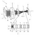
- the single figure shows in a view obliquely from the rear components of a lighting device 1.
- the lighting device 1 has a plurality (here: five) primary light beam units in the form of mutually parallel laser bars 2a to 2e arranged in a plane.
- the laser bars 2a to 2e shown here by way of example horizontally each have a plurality of light sources in the form of (for example nineteen) laser diodes (not shown) which are arranged equidistantly in the longitudinal direction and have primary light of e.g. radiate blue color, here in a direction parallel to a z-direction of the main emission.
- the primary light emitted by the laser diodes forms a primary light beam Pa, Pe with an oblong beam cross section for each of the laser bars 2a to 2e.
- the primary light beams Pa, Pe each have a very high aspect ratio of width (in x-direction) to height (in y-direction).
- the laser bars 2a to 2e and thus also the associated five primary light beams Pa to Pe are equidistant in a vertical direction.
- the laser bars 2a to 2e may only be switched on or off in combination or may be activated or deactivated, in another variant they may also be activated or deactivated individually or in groups.
- the laser bars 2a to 2e are followed by a two-part focusing optics 3, 4, namely a spherical convex plane lens 3 for focusing the primary light beams Pa to Pe in the direction of an optical axis z of the lens 3, which coincides with the z direction.
- the lens 3 is followed by a plano-cylindrical convex lens 4 which, in particular, reduces the width of the primary light beams Pa to Pe.
- the optical axes z of the lenses 3 and 4 are in particular identical and may eg be at a height of the middle laser bar 2c.
- a more than two-part focusing optics can be used (not shown).
- a three-part focusing optics may be used in which, in addition to the lenses 3, 4, in front of each of the laser bars 2a to 2e, there is a respective cylindrical lens (not shown).
- the cylindrical lens may be a FAC ("fast axis collimation") lens for collimating the so-called "fast axis”.
- the optical axis z furthermore passes through a target component 5 connected downstream of the focusing optics 3, 4, of which only an exemplary planar, rectangular and perpendicular to the optical axis z aligned impact region 6 is shown.
- the impact area 6 represents that contiguous area of the target component 5 on which the primary light beams Pa to Pe can impinge.
- the impact area 6 may, for example, have a size of 2 mm ⁇ 1 mm.
- the impact area 6 is displaceable with the target component 5 along the optical axis z as a displacement direction by a predetermined length along a displacement portion L. Its distance along the optical axis z to the focusing optics 3, 4 is thus adjustable. This can be achieved, for example, by means of an electromotive or actuator adjustment drive (not shown), which shifts the target component accordingly.
- a focal point or focal spot of the focusing optics 3, 4 lies in the displacement section L, in particular in the middle of the displacement section L.
- the single spots Fa to Fe of the respective primary light beams Pa to Pe generated on the impact area 6 at different positions S1 to S5 of the displacement section L are shown in a partial image A in a highly schematized manner next to one another.
- the single spots Fa to Fe correspond to the local beam cross section of the associated primary light beams Pa to Pe.
- the middle position S3 corresponds to the location of the focal spot of the focusing optics 3, 4.
- an overall spot F is also drawn, which is defined as a content of a rectangular frame around the individual spots Fa to Fe.
- the total light spot F fills or corresponds to the entire impact area 6.
- the individual luminous spots Fa to Fe are slightly spaced from one another. If the impact area 6 is displaced in the direction S3 towards the next position S5 spaced farther from the focusing optics 3, 4, the individual luminous spots Fa to Fe overlap so that a total luminous spot F obtains a larger aspect ratio and thus becomes narrower. By contrast, the width (in the x-direction) and height (in the y-direction) of the individual light spots Fa to Fe are influenced only slightly. At the position S3 - which corresponds to the focal spot - fall all single light spots Fa to Fe on each other. At the position S4, the individual spots Fa to Fe are again spread apart and are again slightly spaced apart at the position S5. By shifting the target component 5 and thus also the impact area 6, an aspect ratio of the total luminous spot F can thus be varied considerably in a simple manner.
- the impact area 6 can basically be moved stepwise or continuously.
- the beam path of the primary light beams Pa to Pe behind the impingement region 6 is shown as if the impingement region 6 does not shape or deflect the primary light rays Pa to Pe until they strike an imaginary or actually existing image plane B.
- the target component 5 will usually cause beam shaping and / or beam deflection.
- the target component 5 may have at least one transmitted-light optical element, e.g. be at least a lens, a collimator or a diffuser.
- a transmitted light element it may be formed as a light guide, e.g. for endoscopic applications.
- the target component 5 may comprise at least one reflector, for example a micro-mirror actuator.
- the impact area 6 may also be arranged obliquely to the optical axis z.
- the impingement region 6 may in particular comprise phosphor, e.g. be coated with a phosphor layer 7 or a phosphor plate which is applied to the target component 5.
- the target component 5 may alternatively be formed as a self-supporting phosphor body.
- the phosphor layer 7 is shown here in a transmissive arrangement in which the primary light beams Pa to Pe impinge on a first flat side, but the at least partially wavelength-converted useful light is radiated from the second flat side facing away from it.
- the blue primary light rays Pa to Pe impinging on the phosphor layer 7 are partially converted into yellow secondary light, so that the useful light emitted in the direction of the image plane B corresponds to a blue-yellow or white mixture.
- the phosphor layer 7 may also have further phosphors, e.g. blue-red converting phosphor to give the useful light an additional red component to produce a "warm-white" color impression.
- an additional color component of the useful light may also be generated by a primary light beam Pa, Pe, which has an optical spectrum which does not excite the phosphor layer 7 and therefore passes spectrally unchanged through the phosphor layer 7, eg a red or a green primary light beam Pa, Pe.
- the phosphor layer 7 acts as a diffuser for these colors.
- this lighting device 1 is intended to be used with or for use with an image projector, it is particularly advantageous if the aspect ratio of the overall light spot F is adjustable at least approximately in the range of 16: 9 or 4: 3.
- the impact area 6 may be one of a plurality of impact areas of the target component 5, which can be introduced alternately into the primary light beams Pa to Pe.
- the target component 5 may, for example, be a wheel rotatable parallel to the optical axis z, on which a plurality of impingement areas are circumferentially separated from one another on an annular sector, e.g. such as a color wheel, wherein the impact areas can remain in the beam path of the primary light beams Pa to Pe in particular for any time.
- the impact areas can then be selected by adjusting a rotation angle of the target component about its axis of rotation.
- a number may include exactly the specified number as well as a usual tolerance range, as long as this is not explicitly excluded.
Landscapes
- Physics & Mathematics (AREA)
- General Physics & Mathematics (AREA)
- Optics & Photonics (AREA)
- Non-Portable Lighting Devices Or Systems Thereof (AREA)
Applications Claiming Priority (1)
| Application Number | Priority Date | Filing Date | Title |
|---|---|---|---|
| DE102015200736.7A DE102015200736A1 (de) | 2015-01-19 | 2015-01-19 | Beleuchtungsvorrichtung |
Publications (1)
| Publication Number | Publication Date |
|---|---|
| EP3045950A1 true EP3045950A1 (fr) | 2016-07-20 |
Family
ID=54365986
Family Applications (1)
| Application Number | Title | Priority Date | Filing Date |
|---|---|---|---|
| EP15191222.7A Withdrawn EP3045950A1 (fr) | 2015-01-19 | 2015-10-23 | Dispositif d'eclairage |
Country Status (2)
| Country | Link |
|---|---|
| EP (1) | EP3045950A1 (fr) |
| DE (1) | DE102015200736A1 (fr) |
Families Citing this family (1)
| Publication number | Priority date | Publication date | Assignee | Title |
|---|---|---|---|---|
| DE102017121480B4 (de) * | 2017-09-15 | 2024-04-18 | OSRAM Opto Semiconductors Gesellschaft mit beschränkter Haftung | Lichtemittierendes Halbleiterbauteil |
Citations (5)
| Publication number | Priority date | Publication date | Assignee | Title |
|---|---|---|---|---|
| US6044096A (en) * | 1997-11-03 | 2000-03-28 | Sdl, Inc. | Packaged laser diode array system and method with reduced asymmetry |
| US20040067016A1 (en) * | 2002-10-07 | 2004-04-08 | Anikitchev Serguei G. | Method and apparatus for coupling radiation from a stack of diode-laser bars into a single-core optical fiber |
| WO2007078456A1 (fr) * | 2005-12-15 | 2007-07-12 | Mind Melters, Inc. | Système et procédé pour générer une lumière laser intense depuis des matrices à diodes laser |
| US20120113996A1 (en) * | 2010-11-09 | 2012-05-10 | Coherent, Inc. | Line-projection apparatus for arrays of diode-laser bar stacks |
| US20120300178A1 (en) * | 2011-05-25 | 2012-11-29 | Panasonic Corporation | Lighting Device and Projection-Type Display Apparatus Including Lighting Device |
-
2015
- 2015-01-19 DE DE102015200736.7A patent/DE102015200736A1/de not_active Withdrawn
- 2015-10-23 EP EP15191222.7A patent/EP3045950A1/fr not_active Withdrawn
Patent Citations (5)
| Publication number | Priority date | Publication date | Assignee | Title |
|---|---|---|---|---|
| US6044096A (en) * | 1997-11-03 | 2000-03-28 | Sdl, Inc. | Packaged laser diode array system and method with reduced asymmetry |
| US20040067016A1 (en) * | 2002-10-07 | 2004-04-08 | Anikitchev Serguei G. | Method and apparatus for coupling radiation from a stack of diode-laser bars into a single-core optical fiber |
| WO2007078456A1 (fr) * | 2005-12-15 | 2007-07-12 | Mind Melters, Inc. | Système et procédé pour générer une lumière laser intense depuis des matrices à diodes laser |
| US20120113996A1 (en) * | 2010-11-09 | 2012-05-10 | Coherent, Inc. | Line-projection apparatus for arrays of diode-laser bar stacks |
| US20120300178A1 (en) * | 2011-05-25 | 2012-11-29 | Panasonic Corporation | Lighting Device and Projection-Type Display Apparatus Including Lighting Device |
Also Published As
| Publication number | Publication date |
|---|---|
| DE102015200736A1 (de) | 2016-07-21 |
Similar Documents
| Publication | Publication Date | Title |
|---|---|---|
| DE102014202090B4 (de) | Beleuchtungsvorrichtung mit einer Wellenlängenkonversionsanordnung | |
| AT505107B1 (de) | Mikrolinsenarray, optisches modul und scheinwerfer | |
| EP3108174B1 (fr) | Dispositif d'éclairage équipé d'un moyen de conversion | |
| DE102012220570B4 (de) | Projektionsanordnung | |
| DE102015208171B4 (de) | Bestrahlungsvorrichtung mit Strahlungseinheit | |
| DE102012219387B4 (de) | Beleuchtungsvorrichtung mit Pumplichtquelle und Leuchtstoffanordnung und Verfahren zum Betreiben einer solchen Beleuchtungsvorrichtung | |
| EP2288843B1 (fr) | Lampe de lecture ou spot | |
| EP3168527B1 (fr) | Module d'éclairage pour un phare de véhicule automobile et phare de véhicule automobile comprenant un tel module | |
| DE102013208549B4 (de) | Leuchtstoffrad und Beleuchtungsvorrichtung mit diesem Leuchtstoffrad und einer Pumplichtquelle | |
| WO2013178415A1 (fr) | Lentille à couche de réflexion réfléchissant vers l'intérieur | |
| DE102014217521A1 (de) | Beleuchtungsvorrichtung zur variablen Beleuchtung | |
| DE102014110599A1 (de) | Beleuchtungsvorrichtung für Fahrzeuge | |
| DE102016213380A1 (de) | Optisches element und beleuchtungsvorrichtung | |
| WO2014165890A1 (fr) | Unité d'éclairage pour projecteur de véhicule | |
| EP2901072B1 (fr) | Module d'éclairage annulaire | |
| DE102014221668B4 (de) | Beleuchtungsvorrichtung | |
| DE102016206950A1 (de) | Lichtmodul zum Bereitstellen von Licht hoher Leuchtdichte und Beleuchtungsvorrichtung mit diesem Lichtmodul | |
| EP3186675A1 (fr) | Dispositif d'éclairage équipé d'un ensemble de conversion de longueur d'onde | |
| DE102016103717A1 (de) | Pixellichtquelle | |
| DE102017213103A1 (de) | Beleuchtungssystem und scheinwerfer | |
| EP3086025A1 (fr) | Unite de rayonnement pour une lampe chirurgicale | |
| EP3045950A1 (fr) | Dispositif d'eclairage | |
| DE102017222632B4 (de) | Beleuchtungsvorrichtung | |
| WO2013092078A1 (fr) | Système de projection comprenant plusieurs éléments luminescents | |
| DE102016223227A1 (de) | Beleuchtungsvorrichtung |
Legal Events
| Date | Code | Title | Description |
|---|---|---|---|
| PUAI | Public reference made under article 153(3) epc to a published international application that has entered the european phase |
Free format text: ORIGINAL CODE: 0009012 |
|
| AK | Designated contracting states |
Kind code of ref document: A1 Designated state(s): AL AT BE BG CH CY CZ DE DK EE ES FI FR GB GR HR HU IE IS IT LI LT LU LV MC MK MT NL NO PL PT RO RS SE SI SK SM TR |
|
| AX | Request for extension of the european patent |
Extension state: BA ME |
|
| STAA | Information on the status of an ep patent application or granted ep patent |
Free format text: STATUS: THE APPLICATION IS DEEMED TO BE WITHDRAWN |
|
| 18D | Application deemed to be withdrawn |
Effective date: 20170121 |