EP3046859B1 - Bras de mise électrique à la terre - Google Patents
Bras de mise électrique à la terre Download PDFInfo
- Publication number
- EP3046859B1 EP3046859B1 EP15811828.1A EP15811828A EP3046859B1 EP 3046859 B1 EP3046859 B1 EP 3046859B1 EP 15811828 A EP15811828 A EP 15811828A EP 3046859 B1 EP3046859 B1 EP 3046859B1
- Authority
- EP
- European Patent Office
- Prior art keywords
- main body
- grounding arm
- electrical grounding
- base frame
- leaf springs
- Prior art date
- Legal status (The legal status is an assumption and is not a legal conclusion. Google has not performed a legal analysis and makes no representation as to the accuracy of the status listed.)
- Not-in-force
Links
- 230000002093 peripheral effect Effects 0.000 claims description 9
- 239000012530 fluid Substances 0.000 claims description 3
- 238000005452 bending Methods 0.000 description 9
- 230000003068 static effect Effects 0.000 description 8
- 229910001220 stainless steel Inorganic materials 0.000 description 7
- 239000010935 stainless steel Substances 0.000 description 7
- 230000005611 electricity Effects 0.000 description 6
- 230000000712 assembly Effects 0.000 description 4
- 238000000429 assembly Methods 0.000 description 4
- 230000008878 coupling Effects 0.000 description 4
- 238000010168 coupling process Methods 0.000 description 4
- 238000005859 coupling reaction Methods 0.000 description 4
- 239000002184 metal Substances 0.000 description 4
- 230000037361 pathway Effects 0.000 description 3
- 239000000463 material Substances 0.000 description 2
- 238000000034 method Methods 0.000 description 2
- 229910000831 Steel Inorganic materials 0.000 description 1
- 238000009825 accumulation Methods 0.000 description 1
- 239000004020 conductor Substances 0.000 description 1
- 238000007599 discharging Methods 0.000 description 1
- 230000003670 easy-to-clean Effects 0.000 description 1
- 230000000694 effects Effects 0.000 description 1
- 230000002708 enhancing effect Effects 0.000 description 1
- 230000007613 environmental effect Effects 0.000 description 1
- 239000007788 liquid Substances 0.000 description 1
- 238000012423 maintenance Methods 0.000 description 1
- 230000000737 periodic effect Effects 0.000 description 1
- 230000002028 premature Effects 0.000 description 1
- 238000005096 rolling process Methods 0.000 description 1
- 239000010959 steel Substances 0.000 description 1
- 238000003466 welding Methods 0.000 description 1
Images

Classifications
-
- H—ELECTRICITY
- H05—ELECTRIC TECHNIQUES NOT OTHERWISE PROVIDED FOR
- H05F—STATIC ELECTRICITY; NATURALLY-OCCURRING ELECTRICITY
- H05F1/00—Preventing the formation of electrostatic charges
-
- H—ELECTRICITY
- H05—ELECTRIC TECHNIQUES NOT OTHERWISE PROVIDED FOR
- H05F—STATIC ELECTRICITY; NATURALLY-OCCURRING ELECTRICITY
- H05F3/00—Carrying-off electrostatic charges
- H05F3/02—Carrying-off electrostatic charges by means of earthing connections
Definitions
- the present invention relates to a vibratory conveyor comprising a base frame, a reciprocally movable conveyor bed, a multiplicity of leaf springs and an electrical grounding arm.
- Vibratory conveyors have been used for decades in various industrial applications.
- vibratory conveyors include a base frame, and a vibratory conveyor bed which is mounted in spaced relation relative to the base frame, and which further reciprocates in a given pattern in order to move a product, or objects of interest along a given course of travel for further processing.
- static electricity may build up in either the base frame, or the vibratory conveyor, and which must be dissipated in order to avoid an accidental discharge of the static electricity. It is well known that these electrical discharges of static electricity may cause damage to the vibratory conveyor; electrical devices in the area of the vibratory conveyor, or potentially can ignite combustible materials in the region of the electrical discharge.
- this electrical coupling has, heretofore, been achieved by a stainless steel braided cable which had crimped end connections which allowed the stainless steel cable or strap to be secured to the vibratory conveyor, and to the underlying base frame.
- this stainless steel braided cable typically was electrically connected by way of the fasteners which had been employed to secure a plurality of supporting, flexible leaf springs to the base frame, and conveyor bed. These flexible leaf springs supported the movement of the vibratory conveyor in spaced relation relative to the base frame.
- sheet metal straps were used, and which were fabricated in a manner so as to allow the stainless steel straps to be secured in the same manner as the earlier employed steel braided cable, to the leaf springs which support the vibratory conveyor bed. Again, this metal strap was still subjected to the same vibratory force experienced by the conveyor bed, and consequently a bending failure occurred in the stainless steel strap at the point where the metal strap was secured by fasteners to the conveyor bed. Further, a rolling configuration made from a strap of stainless steel was attempted.
- An electrical grounding arm is the subject matter of the present invention.
- US 5,054,605 A describes a conveyor system for conveying items including a carrier for such items to be moved between at least two spaced-apart stations and a first guide track extending between the spaced apart stations.
- a flexible drive tape having a leading edge and a trailing edge is reciprocably mounted within the first guide track for moving the carrier between the spaced-apart stations, wherein the flexible drive tape is attached to the carrier adjacent the leading edge by a plurality of connectors. At least one of the connectors allows controlled relative movement between the tape and the carrier.
- US 2014/097065 A1 describes an excited frame vibratory conveyor which includes a base frame, a motor mount made integral and with the base frame, a pair of vibratory motors mounted on the motor mount, and an electrical circuit for energizing the pair of vibratory motors in a fashion which reduces movement of the base frame in a vertical direction.
- a first aspect of the present invention relates to a vibratory conveyor according to claim 1.
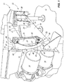
- a vibratory conveyor 11 of traditional design is illustrated.
- the vibratory conveyor is positioned in spaced relation relative to an underlying supporting surface 12.
- the vibratory conveyor includes an elongated base frame 13 which is mounted in spaced relation relative to the supporting surface 12.
- the base frame 13 further mounts a drive assembly 14 of traditional design.
- the drive assembly when energized, imparts energy or force into the base frame 13, and which is subsequently transmitted to a reciprocally movable conveyor bed which is disposed in spaced relation relative thereto.
- the conveyor bed will be discussed in detail, below.
- the vibratory conveyor 11, as discussed, above, includes a reciprocally movable conveyor bed, which is generally indicated by the numeral 20.
- the conveyor bed 20 has a bottom surface 21, and which is positioned in spaced relation relative to the base frame 13.
- the base frame, and conveyor bed, 13 and 20, respectively constitute first and second, spaced objects which cooperate together, and wherein at least one of the first or second spaced objects moves, one relative to the other.
- the drive assembly 14 imparts energy or force into the base frame which is subsequently transmitted to the conveyor bed 20, so as to facilitate a reciprocal motion of the conveyor bed 20 relative to the base frame 13.
- the respective mounting fixtures 23, have a base plate 24, and which is affixed, as by welding or the like, to the respective base frame 13, or conveyor bed 20.
- the base plate 24, therefore, provides an electrical connection to these respective assemblies.
- a post 25 which is also formed of an electrically conductive material.
- the outwardly extending post has opposite sides 26.
- fastener apertures, which are generally indicated by the numeral 27, pass or extend through the outwardly extending post 25. This is seen in Fig. 2 .
- the vibratory conveyor 11 utilizes individual leaf springs 30 of traditional design, and which moveably support the conveyor bed 20 in spaced relation to the base frame 13.
- the respective leaf springs are well known, and have a main body 31 with opposite first and second ends 32 and 33 respectively.
- the respective leaf springs 31 extend upwardly from the base frame 13 to support the conveyor bed 20 in spaced relation relative thereto.
- fastener apertures 34 are formed in the opposite first and second ends 32 and 33 respectively.
- FIG. 1 A clamping plate 36, of traditional design, is provided, and which is operable to sandwich the respective first and second ends 32 and 33 of the individual leaf springs between the clamping plate 36, and the opposite sides 26 of the outwardly extending post 25.
- This fastening technique is well known in the art.
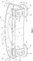
- the electrical grounding arm 10 as seen in Fig. 1 includes an elongated main body which is generally indicated by the numeral 40.
- the elongated main body is electrically conductive, and further has a first end 41, and an opposite second end 42.
- the main body has a length dimension, as measured between the opposite first and second ends 41 and 42, and which is greater than a length dimension of the respective individual leaf springs 30, as previously described.
- the main body 40 has a width dimension which is variable, but which is typically not greater than the width dimension of the multiplicity of leaf springs 30 as earlier described.
- the main body 40 further has an intermediate portion 43, and which is located between the first and second ends 41 and 42.
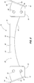
- the main body 40 has a width dimension which, on the one hand, diminishes when measured in a direction extending from the first and second ends respectively 41 and 42, and toward the intermediate portion 43; or, on the other hand, increases when measured from the intermediate portion 43, and in the direction of the first and second ends 41 and 42, respectively.
- the main body 40 has spaced, generally longitudinally extending peripheral edges 44, and which extend between the opposite first and second ends 41 and 42. Still further, the main body 40 has an exterior facing surface 45.
- the electrical grounding arm 10 has an exterior facing surface 45 which has a unique geometry such that no portion of the exterior facing surface of the electrical grounding arm has a region upon which a source of a fluid may pool, or collect, so as to create an unsanitary condition as may be the case when a vibratory conveyor of the current design 11 is employed in food processing applications.
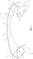
- the main body 40 has a geometry which includes a curvature in the main body 40, and which extends longitudinally relative thereto, and between the first and second ends 41 and 42 respectively. As illustrated in the drawings ( Fig.
- the longitudinally extending peripheral edges 44 include a first peripheral edge 46, which is substantially straight along a preponderance of its length; and a second peripheral edge 47, and which is spaced therefrom, and which has a predetermined curvature as seen in Figs. 2 and 5 .
- the geometry of the main body 40 provides other benefits as will be discussed in greater detail, below.
- the main body 40 of the electrical grounding arm 10 includes a pair of laterally extending arms that are generally indicated by the numeral 50, and which are individually mounted to, or made integral with, the first and second ends 41 and 42, thereof.
- the pair of laterally extending arms 50 include a first arm 51, which extends laterally outwardly from the first end 41; and a second arm 52 which extends laterally outwardly relative to the second end 42 of the main body 40.
- Each of the first and second arms 51 and 52 are formed of a first portion 53 which is made integral with, and extends outwardly relative to the opposite first and second ends 41 and 42 respectively.
- first and second arms 51 and 52 has a second portion 54, and which is made integral with the first portion 53, and which is positioned substantially perpendicular relative thereto.
- the second portion 54 has a given angular geometry relative to the first portion, and it further has a pair of fastening apertures 55 which are formed therethrough.
- a predetermined gap 56 is defined between the second portion 54, and the respective first and second ends 41 and 42 respectively.
- the second portion 54 is sandwiched, or otherwise clamped between the respective ends 32 and 33 of one of the leaf springs 30 as illustrated in the drawings, and one of the opposite sides 26, of the outwardly extending post 25, and which are made integral with a mounting fixture 23.
- the fastening apertures 55 are formed in a fashion so that they individually coaxially align with, and can receive therethrough the individual fasteners 34 which extend through the outwardly extending post 25. Again, the leaf springs, and the second portion 55 are held in place by the clamping plate 36. As will be recognized in this arrangement, the elongated main body 40 of the grounding arm 10 is clamped into a secure, electrically conductive relationship relative to the outwardly extending post 25 thereby securably electrically coupling the main body 40 in an orientation so as to effectively conduct electrical current between the vibratory conveyor bed 20, and the underlying and spaced base frame 13.
- the present electrical grounding arm 10 has a unique geometry which provides an effective means for the electrical grounding arm 10 to dissipate stress which is imparted to the main body 40 by the reciprocal motion of the conveyor bed 20.
- the motion of the conveyor bed 20, causes a corresponding motion to the individual leaf springs 30, and which support the conveyor bed 20 in spaced relation relative to the base frame 13.
- the bending stress imparted by the movement to the main body 40 is dissipated by the geometry of the main body 40 so as to inhibit any stress related damage from being imparted to the electrical grounding arm 10.
- the unique geometry features of the main body 40 include that it is curved. This is seen in Fig.
- the unique width dimensions of the main body that is, that the width of the main body 40 diminishes when measured from the opposite first and second ends 41 and 42 towards the intermediate portion 43 ( Fig. 5 ) is effective, to so some degree, to dissipate the stress imparted to the main body 40 by the reciprocal motion of the conveyor bed 20.
- the peripheral edges, 60, of the first and second ends of the respective leaf springs 32 and 33 are generally perpendicular relative to the longitudinal axis of the respective springs.
- the first portion 53 of the respective pair of laterally extending arms 50 is oriented in an angularly outwardly extending orientation relative to ends of the respective leaf springs 30.
- the second portion 54 is oriented in substantially parallel, juxtaposed relation relative to the first and second ends 32 and 33 of the respective leaf springs 30. It has been discovered that the geometry, as illustrated, and described herein, is effective in dissipating the bending stress imparted by the reciprocal motion of the conveyor bed 20 to the main body 40 thereby enhancing the longevity of the grounding arm's operational lifetime, and preventing the grounding arm from breaking electrical contact between the conveyor bed 20 and the base frame 13.
- the present invention includes, or is directed to, an electrical grounding arm 10 which has an elongated, electrically conductive main body 40.
- the main body 40 has opposite first and second ends 41 and 42, and which are respectively electrically coupled to a first and second spaced object, here indicated by the numerals 13 and 20, respectively, and which movably cooperate, together.
- the main body 40 of the electrical grounding arm 10 has a predetermined geometry, and wherein the motion of one of the first or second objects 13 and 20, respectively, imparts motion to the electrical grounding arm 10.
- the motion of the electrical grounding arm 10 imparts stress to the main body 40 thereof.
- the geometry of the main body 40 of the electrical grounding arm 10 dissipates the stress imparted to the main body 40 so as to inhibit stress related damage from being imparted to the electrical grounding arm 10.
- past attempts to electrically couple two moving objects together has resulted in failure of the electrical coupling due to the bending forces imparted on the electrical pathway coupling the two objects together.
- the main body 40 of the electrical grounding arm 10 has an exterior facing surface 45.
- the geometry of the main body 40 of the electrical grounding arm 10 has no exterior facing surfaces 45 upon which a source of a fluid may pool or collect so as to create an unsanitary condition. This feature is particularly important when a vibratory conveyor 11, such as illustrated in Fig. 1 is employed in food processing applications.
- the main body 40 of the electrical grounding arm 10 has an intermediate portion 43, and which is located between the first and second ends 41 and 42 thereof. Further, the main body 40 has opposite, longitudinally oriented peripheral edges 44. The main body 40 has a width dimension which increases when measured in a direction extending from the intermediate portion 43 of the main body 40 and in the direction of the first and second ends 41 and 42 thereof. As seen in the drawings, at least one of the opposite, longitudinally oriented peripheral edges 44 of the main body 40, has a predetermined curvature which is generally indicated by the numeral 47.
- the main body 40 of the electrical grounding arm 10 has a pair of laterally extending arms 50, and which are individually mounted to the first and second ends 41 and 42 thereof.
- the respective laterally extending arms have a first portion 53 which is made integral with the main body 40, and a second portion 54 which is made integral with the first portion 53.
- the first and second portions 53 and 54 are oriented in a perpendicular relationship, one relative to the other.
- the first object comprises a base frame 13 for a vibratory conveyor 11
- the second object comprises a reciprocally movable conveyor bed 20, and which is held in spaced relation relative to the base frame 13 by a multiplicity of leaf springs 30, and which extend in a given direction outwardly from the base frame 30, and which further support the conveyor bed 20 for movement relative to the base frame 13.
- the respective leaf springs 30 are mounted to each of the base frame 13, and conveyor bed 20 by electrically conductive mounting fixtures 23.
- the second portion 54 of the laterally extending arms 50 are located between at least one of the leaf springs 30, and one of the underlying mounting fixtures 23, and which is located on, and electrically coupled to either the base frame 13, or the conveyor bed 20.
- the electrical grounding arm 10 is electrically coupled, as by clamping, to the base frame 30, and the conveyor bed 20.
- the geometry of the electrical grounding arm 10 is such that the intermediate portion 43 of the main body 40 is located in predetermined spaced relation relative to the underlying leaf springs 30.
- the present invention 10 provides a convenient means whereby spaced objects, here shown as a base frame 13, and a conveyor bed 20, and which is reciprocally movable relative thereto, may be electrically coupled together in a predetermined way so as to provide a dissipation of a static electrical charge in a manner not possible heretofore.
- the present invention is robust; resists bending and other stress related damage which might be imparted to same by the continued reciprocal movement of the conveyor bed; and further, has a geometry which is easy to clean and prevents the accumulation of liquids and other materials which might pool or collect on the exterior facing surface 45 so as to create an unsanitary and unsafe environment.
Landscapes
- Jigging Conveyors (AREA)
- Apparatus For Radiation Diagnosis (AREA)
Claims (6)
- Convoyeur vibratoire (11) comportant un cadre de base (13), un lit convoyeur (20) mobile alternativement, une multiplicité de ressorts à lames (30) et un bras (10) de mise à la terre électrique, le bras (10) de mise à la terre comprenant :
un corps principal (40) allongé, électriquement conducteur ayant des première et seconde extrémités opposées (41, 42) et qui sont respectivement couplées électriquement à un premier et un second objet espacés qui coopèrent ensemble, et dans lequel au moins l'un des premier ou second objets espacés se déplace par rapport à l'autre objet, et dans lequel le premier objet comporte le cadre de base (13) du convoyeur vibratoire (11), et le second objet comporte le lit convoyeur (20) mobile alternativement, et qui est maintenu dans une relation espacée relativement au cadre de base (13) par la multiplicité de ressorts à lames (30) qui s'étendent dans une direction déterminée à l'extérieur par rapport au cadre de base (13), et qui supporte le lit convoyeur (20) pour un déplacement par rapport au cadre de base (13), et dans lequel la multiplicité de ressorts à lames (30) est montée à chacun des cadres de base (13), et du lit convoyeur (20) par des fixations de montages (23) électriquement conductrices, et dans lequel le corps principal (40) du bras de mise à la terre électrique (10) a une géométrie prédéterminée, et le corps principal (40) du bras de mise à la terre électrique (10) comporte une surface extérieure de contact (45), et la géométrie du corps principal (40) du bras de mise à la terre électrique (10) ne comporte aucune surface de contact extérieure sur laquelle une source de fluide puisse s'écouler, ou être collectée de manière à créer des conditions insalubres, et dans lequel le corps principal (40) du bras de mise à la terre électrique (10) a une portion intermédiaire (43) qui est disposée entre la première et la seconde extrémités (41, 42), et opposés, longitudinalement orientés à la périphérie des bords (44), et dans lequel le corps principal (40) a une dimension de largeur et dans lequel la dimension de largeur du corps principal (40) augmente lorsqu'elle est mesurée dans une direction qui s'étend de la portion intermédiaire (43) du corps principal (40), et dans la direction de leurs première et seconde extrémités (41, 42), et dans lequel au moins un des bords périphériques (44) orientés longitudinalement opposés, du corps principal (40) a une courbure prédéterminée, et le corps principal (40) comporte des bras s'entendant latéralement qui sont individuellement montés à leur première et secondes extrémité (41, 42), et qui comportent une première portion (53) qui est rendue intégrale avec le corps principal (40), et une seconde portion (54) qui est rendue intégrale avec la première portion (53), et dans lequel la première et la seconde portions (53, 54) sont orientées dans une relation perpendiculaire, l'une par rapport à l'autre, et dans lequel la seconde portion (54) des bras s'étendant latéralement est localisée entre au moins un des ressorts à lames (30), et l'une des fixations de montages (23) sous-jacente, qui est montée sur, et électriquement couplée avec le cadre de base (40) et le lit convoyeur (20), de manière à coupler électriquement le cadre de base (40) et le lit convoyeur (20) ensemble, et dans lequel le déplacement de l'un des premiers ou seconds objets confère un mouvement au bras de mise à la terre électrique (10), qui est électriquement couplé avec chacun des premier et second objets espacés, et dans lequel le déplacement du bras de mise à la terre électrique (10) confère une tension sur le corps principal (40) de celui-ci, et dans lequel la géométrie du corps principal (40) du bras de mise à la terre électrique (10) dissipe la contrainte imposée au corps principal (40) de manière à éviter tout endommagement relatif à la contrainte conférée au bras de mise à la terre électrique (10). - Convoyeur vibratoire (11) selon la revendication 1, et dans lequel les bras s'étendant latéralement du bras de mise à la terre électrique (10) positionnent la portion intermédiaire (43) du corps principal (40) dans une relation d'espacement prédéterminé relativement aux ressorts à lame (30).
- Convoyeur vibratoire (11) selon la revendication 1, et dans lequel la multiplicité de ressorts à lames (30) s'étend vers le haut par rapport au cadre de base (13), et dans lequel les première et seconde extrémités (41, 42) du corps principal (40) du bras de mise à la terre électrique (10) sont respectivement, électriquement connectés aux fixations de montages (23) individuelles disposées sur le cadre de base (40), et le lit convoyeur (20), et dans lequel la dimension de largeur du corps principal (40) diminue lorsqu'elle est mesurée depuis les première et secondes extrémités opposées (41, 42), et dans la direction de la portion intermédiaire (43) du corps principal (40), et dans lequel le corps principal (40) comporte une portion disposée centralement et incurvée, et individuelle, localisée à distance, et des bras s'étendant latéralement, et qui sont disposés aux première et seconde extrémités opposées (41, 42) du corps principal (40), et dans lequel la première portion (53) des bras respectifs s'étendant latéralement est réalisé intégralement avec la portion incurvée du corps principal (40), et la seconde portion (54) est électriquement connectée à l'un des premier ou second objets espacés, et dans lequel la première et la seconde portions des bras s'étendant latéralement sont perpendiculaires l'une par rapport à l'autre.
- Convoyeur vibratoire (11) selon la revendication 3, et dans lequel les ressorts à lames respectifs (30) ont tous une dimension de longueur prédéterminée, et le bras de mise à la terre électrique (10) a une dimension de longueur supérieure à la dimension de longueur des ressorts à lame respectifs (30).
- Convoyeur vibratoire (11) selon la revendication 4, et dans lequel les ressorts à lames respectifs (30) ont chacun une dimension de largeur prédéterminée et uniforme et dans lequel la dimension de largeur maximale du corps principal (40) du bras de mise à la terre électrique (10) est égale à la dimension de largeur des ressorts à lames respectifs (30).
- Convoyeur vibratoire (11) selon la revendication 5, et dans lequel chacune des fixations de montages (23), a un poste (25) s'étendant vers l'extérieur ayant des côtés opposés (26), et dans lequel les ressorts à lames (30) individuels sont montés chacun sur les côtés opposés (26) du poste (25) s'étendant vers l'extérieur, et dans lequel la seconde portion (54) de chacun des bras s'étendant latéralement est pris en sandwich entre au moins un des ressorts à lames (30), et le poste (25) sous-jacent s'étendant vers l'extérieur de la fixation de montage (23) auquel le ressort à lames (30) disposé au-dessus est attaché, de manière à réaliser une connexion électrique entre le bras de mise à la terre électrique (10) et la fixation de montage (23).
Applications Claiming Priority (2)
| Application Number | Priority Date | Filing Date | Title |
|---|---|---|---|
| US14/312,387 US9408283B2 (en) | 2014-06-23 | 2014-06-23 | Electrical grounding arm |
| PCT/US2015/030720 WO2015199831A1 (fr) | 2014-06-23 | 2015-05-14 | Bras de mise électrique à la terre |
Publications (3)
| Publication Number | Publication Date |
|---|---|
| EP3046859A1 EP3046859A1 (fr) | 2016-07-27 |
| EP3046859A4 EP3046859A4 (fr) | 2017-05-17 |
| EP3046859B1 true EP3046859B1 (fr) | 2018-06-27 |
Family
ID=54871018
Family Applications (1)
| Application Number | Title | Priority Date | Filing Date |
|---|---|---|---|
| EP15811828.1A Not-in-force EP3046859B1 (fr) | 2014-06-23 | 2015-05-14 | Bras de mise électrique à la terre |
Country Status (6)
| Country | Link |
|---|---|
| US (1) | US9408283B2 (fr) |
| EP (1) | EP3046859B1 (fr) |
| AU (1) | AU2015280664B2 (fr) |
| CA (1) | CA2928427C (fr) |
| MX (1) | MX2016005016A (fr) |
| WO (1) | WO2015199831A1 (fr) |
Families Citing this family (3)
| Publication number | Priority date | Publication date | Assignee | Title |
|---|---|---|---|---|
| US11089810B2 (en) | 2018-04-26 | 2021-08-17 | Vibratory Solutions, Llc | Vibratory batter application |
| US11142409B1 (en) | 2020-04-27 | 2021-10-12 | Vibratory Solutions, Llc | Conveyor system with orientation of conveyed food products |
| CN115954690B (zh) * | 2023-03-13 | 2023-05-23 | 江天科技有限公司 | 一种接地架的接地结构 |
Family Cites Families (9)
| Publication number | Priority date | Publication date | Assignee | Title |
|---|---|---|---|---|
| US5054605A (en) | 1990-03-29 | 1991-10-08 | Bavis Edward F | Flexible drive conveyor system |
| US6286658B1 (en) | 1999-08-12 | 2001-09-11 | Key Technology, Inc. | Vibratory conveyor |
| US7136271B2 (en) | 2003-03-17 | 2006-11-14 | Illinois Tool Works Inc | Static charge neutralizing assembly for use on rollers and shafts |
| US6921064B2 (en) | 2003-12-22 | 2005-07-26 | Xerox Corporation | Metering blade suspension system |
| CA2726464C (fr) | 2008-06-25 | 2015-03-31 | Brunes, Per | Convoyeur vibrant |
| US9533770B2 (en) * | 2011-03-16 | 2017-01-03 | Airbus Operations Limited | Aircraft bonding network |
| US8517168B2 (en) | 2011-06-20 | 2013-08-27 | Key Technology, Inc. | Spring for a vibratory conveyor |
| US9688419B2 (en) * | 2012-06-08 | 2017-06-27 | The Boeing Company | Composite tubes for a fluid transport system |
| US8733540B2 (en) | 2012-10-10 | 2014-05-27 | Key Technology, Inc. | Excited frame vibratory conveyor |
-
2014
- 2014-06-23 US US14/312,387 patent/US9408283B2/en active Active
-
2015
- 2015-05-14 CA CA2928427A patent/CA2928427C/fr not_active Expired - Fee Related
- 2015-05-14 AU AU2015280664A patent/AU2015280664B2/en not_active Ceased
- 2015-05-14 MX MX2016005016A patent/MX2016005016A/es unknown
- 2015-05-14 WO PCT/US2015/030720 patent/WO2015199831A1/fr not_active Ceased
- 2015-05-14 EP EP15811828.1A patent/EP3046859B1/fr not_active Not-in-force
Non-Patent Citations (1)
| Title |
|---|
| None * |
Also Published As
| Publication number | Publication date |
|---|---|
| CA2928427A1 (fr) | 2015-12-30 |
| EP3046859A1 (fr) | 2016-07-27 |
| CA2928427C (fr) | 2016-11-15 |
| MX2016005016A (es) | 2016-06-24 |
| US20150373820A1 (en) | 2015-12-24 |
| US9408283B2 (en) | 2016-08-02 |
| WO2015199831A1 (fr) | 2015-12-30 |
| AU2015280664B2 (en) | 2019-02-28 |
| EP3046859A4 (fr) | 2017-05-17 |
Similar Documents
| Publication | Publication Date | Title |
|---|---|---|
| EP3046859B1 (fr) | Bras de mise électrique à la terre | |
| CA2871032C (fr) | Unite d'entrainement a chaine | |
| EP2386505A1 (fr) | Courroie transporteuse | |
| CN103056877B (zh) | 机械手 | |
| AU2015280664A1 (en) | Electrical grounding arm | |
| JP6286750B2 (ja) | コンベヤチェーンリンク、コンベヤチェーン、コンベヤチェーン用の駆動ホイール、及びそのような駆動ホイールを備えるシステム | |
| US11018469B2 (en) | Current collector and conductor line system | |
| AU2017269248A1 (en) | Roller system having spaced apart external rotor motor | |
| US20160081236A1 (en) | Conductive clip | |
| WO2013122863A1 (fr) | Ensemble frotteur segmenté | |
| US20160340128A1 (en) | Conveyor belt scraper | |
| US9166389B2 (en) | Assembly comprising a raceway and a branching device, and associated branching device | |
| KR20150094237A (ko) | 급전 레일의 신축흡수장치 | |
| US9415941B2 (en) | Vibration generating assembly | |
| WO2015193907A1 (fr) | Élément flexible pour un système de transport | |
| EP1388919A2 (fr) | Dispositif de support pour câble ruban | |
| US10053304B2 (en) | Holder | |
| EP4061752A1 (fr) | Transporteur, système de transport et procédé de fabrication de transporteur | |
| CN207840870U (zh) | 一种工件加工装置 | |
| CN219788389U (zh) | 制动装置、机器人关节及机器人 | |
| CN105691283A (zh) | 一种用于物流货物箱的压紧固定结构及其运行方法 | |
| WO2000078648A1 (fr) | Ensemble de calage des essieux d'un transporteur a rouleaux mecanises | |
| CN203789000U (zh) | 一种用于滑轨式刀削面机器人的联排削面刀头 | |
| CN214921504U (zh) | 激光切割机的防碰撞装置 | |
| EP2338812A1 (fr) | Système de support pour courroies de transport de marchandises |
Legal Events
| Date | Code | Title | Description |
|---|---|---|---|
| PUAI | Public reference made under article 153(3) epc to a published international application that has entered the european phase |
Free format text: ORIGINAL CODE: 0009012 |
|
| 17P | Request for examination filed |
Effective date: 20160420 |
|
| AK | Designated contracting states |
Kind code of ref document: A1 Designated state(s): AL AT BE BG CH CY CZ DE DK EE ES FI FR GB GR HR HU IE IS IT LI LT LU LV MC MK MT NL NO PL PT RO RS SE SI SK SM TR |
|
| AX | Request for extension of the european patent |
Extension state: BA ME |
|
| A4 | Supplementary search report drawn up and despatched |
Effective date: 20170421 |
|
| RIC1 | Information provided on ipc code assigned before grant |
Ipc: B65G 27/26 20060101AFI20170413BHEP Ipc: H05F 3/02 20060101ALI20170413BHEP |
|
| DAV | Request for validation of the european patent (deleted) | ||
| DAX | Request for extension of the european patent (deleted) | ||
| GRAP | Despatch of communication of intention to grant a patent |
Free format text: ORIGINAL CODE: EPIDOSNIGR1 |
|
| STAA | Information on the status of an ep patent application or granted ep patent |
Free format text: STATUS: GRANT OF PATENT IS INTENDED |
|
| RIC1 | Information provided on ipc code assigned before grant |
Ipc: B65G 27/26 20060101AFI20171212BHEP Ipc: H05F 3/02 20060101ALI20171212BHEP |
|
| INTG | Intention to grant announced |
Effective date: 20180117 |
|
| GRAS | Grant fee paid |
Free format text: ORIGINAL CODE: EPIDOSNIGR3 |
|
| GRAA | (expected) grant |
Free format text: ORIGINAL CODE: 0009210 |
|
| STAA | Information on the status of an ep patent application or granted ep patent |
Free format text: STATUS: THE PATENT HAS BEEN GRANTED |
|
| AK | Designated contracting states |
Kind code of ref document: B1 Designated state(s): AL AT BE BG CH CY CZ DE DK EE ES FI FR GB GR HR HU IE IS IT LI LT LU LV MC MK MT NL NO PL PT RO RS SE SI SK SM TR |
|
| REG | Reference to a national code |
Ref country code: GB Ref legal event code: FG4D |
|
| REG | Reference to a national code |
Ref country code: AT Ref legal event code: REF Ref document number: 1012109 Country of ref document: AT Kind code of ref document: T Effective date: 20180715 |
|
| REG | Reference to a national code |
Ref country code: IE Ref legal event code: FG4D |
|
| REG | Reference to a national code |
Ref country code: DE Ref legal event code: R096 Ref document number: 602015012848 Country of ref document: DE |
|
| REG | Reference to a national code |
Ref country code: NL Ref legal event code: FP |
|
| PG25 | Lapsed in a contracting state [announced via postgrant information from national office to epo] |
Ref country code: SE Free format text: LAPSE BECAUSE OF FAILURE TO SUBMIT A TRANSLATION OF THE DESCRIPTION OR TO PAY THE FEE WITHIN THE PRESCRIBED TIME-LIMIT Effective date: 20180627 Ref country code: BG Free format text: LAPSE BECAUSE OF FAILURE TO SUBMIT A TRANSLATION OF THE DESCRIPTION OR TO PAY THE FEE WITHIN THE PRESCRIBED TIME-LIMIT Effective date: 20180927 Ref country code: FI Free format text: LAPSE BECAUSE OF FAILURE TO SUBMIT A TRANSLATION OF THE DESCRIPTION OR TO PAY THE FEE WITHIN THE PRESCRIBED TIME-LIMIT Effective date: 20180627 Ref country code: NO Free format text: LAPSE BECAUSE OF FAILURE TO SUBMIT A TRANSLATION OF THE DESCRIPTION OR TO PAY THE FEE WITHIN THE PRESCRIBED TIME-LIMIT Effective date: 20180927 Ref country code: LT Free format text: LAPSE BECAUSE OF FAILURE TO SUBMIT A TRANSLATION OF THE DESCRIPTION OR TO PAY THE FEE WITHIN THE PRESCRIBED TIME-LIMIT Effective date: 20180627 |
|
| REG | Reference to a national code |
Ref country code: LT Ref legal event code: MG4D |
|
| PG25 | Lapsed in a contracting state [announced via postgrant information from national office to epo] |
Ref country code: GR Free format text: LAPSE BECAUSE OF FAILURE TO SUBMIT A TRANSLATION OF THE DESCRIPTION OR TO PAY THE FEE WITHIN THE PRESCRIBED TIME-LIMIT Effective date: 20180928 Ref country code: LV Free format text: LAPSE BECAUSE OF FAILURE TO SUBMIT A TRANSLATION OF THE DESCRIPTION OR TO PAY THE FEE WITHIN THE PRESCRIBED TIME-LIMIT Effective date: 20180627 Ref country code: HR Free format text: LAPSE BECAUSE OF FAILURE TO SUBMIT A TRANSLATION OF THE DESCRIPTION OR TO PAY THE FEE WITHIN THE PRESCRIBED TIME-LIMIT Effective date: 20180627 Ref country code: RS Free format text: LAPSE BECAUSE OF FAILURE TO SUBMIT A TRANSLATION OF THE DESCRIPTION OR TO PAY THE FEE WITHIN THE PRESCRIBED TIME-LIMIT Effective date: 20180627 |
|
| REG | Reference to a national code |
Ref country code: AT Ref legal event code: MK05 Ref document number: 1012109 Country of ref document: AT Kind code of ref document: T Effective date: 20180627 |
|
| PG25 | Lapsed in a contracting state [announced via postgrant information from national office to epo] |
Ref country code: CZ Free format text: LAPSE BECAUSE OF FAILURE TO SUBMIT A TRANSLATION OF THE DESCRIPTION OR TO PAY THE FEE WITHIN THE PRESCRIBED TIME-LIMIT Effective date: 20180627 Ref country code: RO Free format text: LAPSE BECAUSE OF FAILURE TO SUBMIT A TRANSLATION OF THE DESCRIPTION OR TO PAY THE FEE WITHIN THE PRESCRIBED TIME-LIMIT Effective date: 20180627 Ref country code: AT Free format text: LAPSE BECAUSE OF FAILURE TO SUBMIT A TRANSLATION OF THE DESCRIPTION OR TO PAY THE FEE WITHIN THE PRESCRIBED TIME-LIMIT Effective date: 20180627 Ref country code: PL Free format text: LAPSE BECAUSE OF FAILURE TO SUBMIT A TRANSLATION OF THE DESCRIPTION OR TO PAY THE FEE WITHIN THE PRESCRIBED TIME-LIMIT Effective date: 20180627 Ref country code: EE Free format text: LAPSE BECAUSE OF FAILURE TO SUBMIT A TRANSLATION OF THE DESCRIPTION OR TO PAY THE FEE WITHIN THE PRESCRIBED TIME-LIMIT Effective date: 20180627 Ref country code: IS Free format text: LAPSE BECAUSE OF FAILURE TO SUBMIT A TRANSLATION OF THE DESCRIPTION OR TO PAY THE FEE WITHIN THE PRESCRIBED TIME-LIMIT Effective date: 20181027 Ref country code: SK Free format text: LAPSE BECAUSE OF FAILURE TO SUBMIT A TRANSLATION OF THE DESCRIPTION OR TO PAY THE FEE WITHIN THE PRESCRIBED TIME-LIMIT Effective date: 20180627 |
|
| PG25 | Lapsed in a contracting state [announced via postgrant information from national office to epo] |
Ref country code: IT Free format text: LAPSE BECAUSE OF FAILURE TO SUBMIT A TRANSLATION OF THE DESCRIPTION OR TO PAY THE FEE WITHIN THE PRESCRIBED TIME-LIMIT Effective date: 20180627 Ref country code: SM Free format text: LAPSE BECAUSE OF FAILURE TO SUBMIT A TRANSLATION OF THE DESCRIPTION OR TO PAY THE FEE WITHIN THE PRESCRIBED TIME-LIMIT Effective date: 20180627 Ref country code: ES Free format text: LAPSE BECAUSE OF FAILURE TO SUBMIT A TRANSLATION OF THE DESCRIPTION OR TO PAY THE FEE WITHIN THE PRESCRIBED TIME-LIMIT Effective date: 20180627 |
|
| REG | Reference to a national code |
Ref country code: DE Ref legal event code: R097 Ref document number: 602015012848 Country of ref document: DE |
|
| PLBE | No opposition filed within time limit |
Free format text: ORIGINAL CODE: 0009261 |
|
| STAA | Information on the status of an ep patent application or granted ep patent |
Free format text: STATUS: NO OPPOSITION FILED WITHIN TIME LIMIT |
|
| PG25 | Lapsed in a contracting state [announced via postgrant information from national office to epo] |
Ref country code: DK Free format text: LAPSE BECAUSE OF FAILURE TO SUBMIT A TRANSLATION OF THE DESCRIPTION OR TO PAY THE FEE WITHIN THE PRESCRIBED TIME-LIMIT Effective date: 20180627 |
|
| 26N | No opposition filed |
Effective date: 20190328 |
|
| PGFP | Annual fee paid to national office [announced via postgrant information from national office to epo] |
Ref country code: NL Payment date: 20190521 Year of fee payment: 5 |
|
| PGFP | Annual fee paid to national office [announced via postgrant information from national office to epo] |
Ref country code: DE Payment date: 20190529 Year of fee payment: 5 |
|
| PG25 | Lapsed in a contracting state [announced via postgrant information from national office to epo] |
Ref country code: SI Free format text: LAPSE BECAUSE OF FAILURE TO SUBMIT A TRANSLATION OF THE DESCRIPTION OR TO PAY THE FEE WITHIN THE PRESCRIBED TIME-LIMIT Effective date: 20180627 |
|
| PGFP | Annual fee paid to national office [announced via postgrant information from national office to epo] |
Ref country code: BE Payment date: 20190521 Year of fee payment: 5 Ref country code: FR Payment date: 20190410 Year of fee payment: 5 |
|
| PGFP | Annual fee paid to national office [announced via postgrant information from national office to epo] |
Ref country code: GB Payment date: 20190528 Year of fee payment: 5 |
|
| PG25 | Lapsed in a contracting state [announced via postgrant information from national office to epo] |
Ref country code: AL Free format text: LAPSE BECAUSE OF FAILURE TO SUBMIT A TRANSLATION OF THE DESCRIPTION OR TO PAY THE FEE WITHIN THE PRESCRIBED TIME-LIMIT Effective date: 20180627 |
|
| REG | Reference to a national code |
Ref country code: CH Ref legal event code: PL |
|
| PG25 | Lapsed in a contracting state [announced via postgrant information from national office to epo] |
Ref country code: MC Free format text: LAPSE BECAUSE OF FAILURE TO SUBMIT A TRANSLATION OF THE DESCRIPTION OR TO PAY THE FEE WITHIN THE PRESCRIBED TIME-LIMIT Effective date: 20180627 Ref country code: LI Free format text: LAPSE BECAUSE OF NON-PAYMENT OF DUE FEES Effective date: 20190531 Ref country code: CH Free format text: LAPSE BECAUSE OF NON-PAYMENT OF DUE FEES Effective date: 20190531 |
|
| PG25 | Lapsed in a contracting state [announced via postgrant information from national office to epo] |
Ref country code: LU Free format text: LAPSE BECAUSE OF NON-PAYMENT OF DUE FEES Effective date: 20190514 |
|
| PG25 | Lapsed in a contracting state [announced via postgrant information from national office to epo] |
Ref country code: TR Free format text: LAPSE BECAUSE OF FAILURE TO SUBMIT A TRANSLATION OF THE DESCRIPTION OR TO PAY THE FEE WITHIN THE PRESCRIBED TIME-LIMIT Effective date: 20180627 |
|
| PG25 | Lapsed in a contracting state [announced via postgrant information from national office to epo] |
Ref country code: IE Free format text: LAPSE BECAUSE OF NON-PAYMENT OF DUE FEES Effective date: 20190514 |
|
| PG25 | Lapsed in a contracting state [announced via postgrant information from national office to epo] |
Ref country code: PT Free format text: LAPSE BECAUSE OF FAILURE TO SUBMIT A TRANSLATION OF THE DESCRIPTION OR TO PAY THE FEE WITHIN THE PRESCRIBED TIME-LIMIT Effective date: 20181029 |
|
| REG | Reference to a national code |
Ref country code: DE Ref legal event code: R119 Ref document number: 602015012848 Country of ref document: DE |
|
| REG | Reference to a national code |
Ref country code: NL Ref legal event code: MM Effective date: 20200601 |
|
| PG25 | Lapsed in a contracting state [announced via postgrant information from national office to epo] |
Ref country code: NL Free format text: LAPSE BECAUSE OF NON-PAYMENT OF DUE FEES Effective date: 20200601 |
|
| REG | Reference to a national code |
Ref country code: BE Ref legal event code: MM Effective date: 20200531 |
|
| GBPC | Gb: european patent ceased through non-payment of renewal fee |
Effective date: 20200514 |
|
| PG25 | Lapsed in a contracting state [announced via postgrant information from national office to epo] |
Ref country code: FR Free format text: LAPSE BECAUSE OF NON-PAYMENT OF DUE FEES Effective date: 20200531 Ref country code: GB Free format text: LAPSE BECAUSE OF NON-PAYMENT OF DUE FEES Effective date: 20200514 |
|
| PG25 | Lapsed in a contracting state [announced via postgrant information from national office to epo] |
Ref country code: BE Free format text: LAPSE BECAUSE OF NON-PAYMENT OF DUE FEES Effective date: 20200531 Ref country code: CY Free format text: LAPSE BECAUSE OF FAILURE TO SUBMIT A TRANSLATION OF THE DESCRIPTION OR TO PAY THE FEE WITHIN THE PRESCRIBED TIME-LIMIT Effective date: 20180627 Ref country code: DE Free format text: LAPSE BECAUSE OF NON-PAYMENT OF DUE FEES Effective date: 20201201 |
|
| PG25 | Lapsed in a contracting state [announced via postgrant information from national office to epo] |
Ref country code: HU Free format text: LAPSE BECAUSE OF FAILURE TO SUBMIT A TRANSLATION OF THE DESCRIPTION OR TO PAY THE FEE WITHIN THE PRESCRIBED TIME-LIMIT; INVALID AB INITIO Effective date: 20150514 Ref country code: MT Free format text: LAPSE BECAUSE OF FAILURE TO SUBMIT A TRANSLATION OF THE DESCRIPTION OR TO PAY THE FEE WITHIN THE PRESCRIBED TIME-LIMIT Effective date: 20180627 |
|
| PG25 | Lapsed in a contracting state [announced via postgrant information from national office to epo] |
Ref country code: MK Free format text: LAPSE BECAUSE OF FAILURE TO SUBMIT A TRANSLATION OF THE DESCRIPTION OR TO PAY THE FEE WITHIN THE PRESCRIBED TIME-LIMIT Effective date: 20180627 |