EP3046860B1 - Übertragungsplatte zum beladen eines laderaums - Google Patents
Übertragungsplatte zum beladen eines laderaums Download PDFInfo
- Publication number
- EP3046860B1 EP3046860B1 EP14846154.4A EP14846154A EP3046860B1 EP 3046860 B1 EP3046860 B1 EP 3046860B1 EP 14846154 A EP14846154 A EP 14846154A EP 3046860 B1 EP3046860 B1 EP 3046860B1
- Authority
- EP
- European Patent Office
- Prior art keywords
- transfer plate
- cargo space
- leaf spring
- positioning means
- load
- Prior art date
- Legal status (The legal status is an assumption and is not a legal conclusion. Google has not performed a legal analysis and makes no representation as to the accuracy of the status listed.)
- Active
Links
Images


Classifications
-
- B—PERFORMING OPERATIONS; TRANSPORTING
- B65—CONVEYING; PACKING; STORING; HANDLING THIN OR FILAMENTARY MATERIAL
- B65G—TRANSPORT OR STORAGE DEVICES, e.g. CONVEYORS FOR LOADING OR TIPPING, SHOP CONVEYOR SYSTEMS OR PNEUMATIC TUBE CONVEYORS
- B65G67/00—Loading or unloading vehicles
- B65G67/02—Loading or unloading land vehicles
-
- B—PERFORMING OPERATIONS; TRANSPORTING
- B65—CONVEYING; PACKING; STORING; HANDLING THIN OR FILAMENTARY MATERIAL
- B65G—TRANSPORT OR STORAGE DEVICES, e.g. CONVEYORS FOR LOADING OR TIPPING, SHOP CONVEYOR SYSTEMS OR PNEUMATIC TUBE CONVEYORS
- B65G67/00—Loading or unloading vehicles
- B65G67/02—Loading or unloading land vehicles
- B65G67/04—Loading land vehicles
- B65G67/20—Loading covered vehicles
-
- B—PERFORMING OPERATIONS; TRANSPORTING
- B65—CONVEYING; PACKING; STORING; HANDLING THIN OR FILAMENTARY MATERIAL
- B65G—TRANSPORT OR STORAGE DEVICES, e.g. CONVEYORS FOR LOADING OR TIPPING, SHOP CONVEYOR SYSTEMS OR PNEUMATIC TUBE CONVEYORS
- B65G69/00—Auxiliary measures taken, or devices used, in connection with loading or unloading
- B65G69/22—Horizontal loading or unloading platforms
Definitions
- the present invention relates to a transfer plate for loading a cargo space, which transfer plate is intended to be moved, together with a load of load units, into the cargo space, and out of the cargo space, while the load of the load units remain in the cargo space, and which transfer plate includes flexible slippery plastic that withstands both pushing and pulling.
- WO publication number 2005080132 discloses a method and apparatus for loading products to be transported into a cargo space.
- a transfer plate is utilized, on top of which the load is first of all formed.
- the load, together with the transfer plate is pushed into the cargo space, after which the transfer plate is pulled out from under the load.
- the load is supported.
- the products are first loaded on a transfer plate, which is outside the cargo space and is to be pushed into the cargo space.
- the products are transferred to the cargo space by pushing the transfer plate inside over the base of the cargo space.
- the products are supported from the open side and the transfer space is pulled out from between the base of the cargo space and the products.
- a frame and a transfer plate on it to be moved there is a frame and a transfer plate on it to be moved.
- the apparatus also includes transfer means for moving the transfer plate and products inside the cargo space and for pulling the transfer plate out from between the base of the cargo space and the products.
- WO publication 2007071831 discloses an application of a transfer plate for loading different pallets into a cargo space. Rolling elements are located on at least part of the length of the transfer plate, so that the pallets can be pushed by a conveyor system backwards on top of the transfer plate.
- the transfer plate can be pulled from under the pallets, while the pallets are in the cargo space, without problems of friction.
- WO01/58789A1 discloses a conveyor which conveys palletized articles to a loading dock.
- a bogie movable along rails between different docks, supports an independently movable carriage, which may roll out of the bogie once it reaches the dock.
- the carriage then loads with a forklift provided on the carriage, the articles into a semi-trailer located at the loading dock.
- the carriage is provided with a linkage pivotally installed on its main frame, the linkage carrying four wheels which protrude laterally beyond all other elements of the carriage.
- the linkage links the guide wheels into a common pivotal displacement, the wheels remaining symmetrical relative to the frame.
- a piston biases the wheels towards an outer position, and the wheels are forcibly pivotable, against the bias, towards an inner position.
- the bogie is provided with fixed lateral railings, and with pivotable gates whose outer free end portions abut against the inner side walls of the semi-trailer
- US4522556 discloses a transfer plate according to the pre
- the invention is intended to create a new type of transfer plate, which is suitable for loading many kinds of cargo space.
- the characterizing features of the present invention are stated in the accompanying Claims.
- the transfer plate according to the invention surprisingly includes means for controlling the transfer plate.
- the transfer plate together with its load can thus be safely pushed into the cargo space without any risk of damage.
- loading automation can be increased, even though the properties of the cargo spaces differ from one another.
- Figure 1 shows an apparatus applying the transfer plate according to the invention.
- the pallets 11 containing loading units 10 are brought by a roller track 13 forming a transfer conveyor 12 to the loading area, in which there are two filling devices 14 and two transfer plates 15 with transfer means 16.
- the second transfer plate 15 can be being filled already.
- several filling devices can be arranged in the loading area.
- a rotation device 19 for rotating pallets 11 is fitted in connection with the intermediate conveyor 17. The pallet can then be rotated in the final stage.
- the intermediate conveyor 17 consists of a transfer device 20, which moves on guides from the transfer conveyor 12 to one or other of the filling devices 14.
- the load unit 10 is pushed from the pallets 11 by a buffer beam 22.
- the load units can also be placed in the filling devices by, for example, a robot or manipulator.
- the load can be formed from the side of the transfer means, for example, by a fork-lift truck, or from above by, for example, a crane.
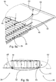
- FIGS 2 and 3 show the transfer plate 15 according to the invention, which is utilized when loading a cargo space.
- the transfer plate is intended to be moved, together with load units, into the cargo space and out of the cargo space while the load units remain in the cargo space.
- rolling elements 23 are arranged on part of the length of the transfer plate 15, on its surface of the side with the load units 10, in order to permit movement between the transfer plate 15 and the load units 10.
- the formation of the load is thus facilitated and the stresses acting on the transfer plate are clearly less than those known. Also the stresses of the load units and other apparatus are less than before.
- the transfer plate 15 includes a flexible slippery plastic 36 that withstands both pushing and pulling.
- the surface of the slippery plastic facing the base of the cargo space is smooth and the plastic material slides over the base. The transfer plate is pushed from its rear edge, but the slippery plastic is sufficiently flexible to conform to the shapes of the base of the cargo space.
- the rolling elements 23 are freely rotating rollers 24, from which roller rails 25 are formed in the longitudinal direction of the transfer plate 15.
- the roller rails can be only a few or closely next to each other.
- a ramp is arranged from the rolling elements 23 to the cargo space. With the aid of the ramp, even sliding of the load units into the cargo space is achieved, without large drops when the transfer plate is pulled out from under the load units.
- a functional ramp 26 is formed of plastic wedges 27, arranged as continuations of the roller rails 25.
- three plastic strips 28, in the edges of which there are in addition bevels 29, are bolted on top of the transfer plate 15, in order to form a ramp 26.
- the same reference numbers are used for functionally similar components.
- the transfer plate 15 is mainly of plastic, being formed of slippery plastic 36, so that it slides easily along the base of the cargo space.
- the surface of the transfer plate opposite to that with the rolling elements is essentially smooth.
- the thin slippery plastic of the transfer plate conforms to unevennesses in the cargo space and even permits uneven bases in cargo spaces.
- the weight of the load is distributed evenly over the area of the cargo space and there can even be large openings in the cargo space.
- the plastic transfer plate, more specifically the slippery plastic slides without catching on different kinds of base.
- the floor of the cargo space can then be, for example, of steel, wood, plywood, or aluminium.
- the good sliding properties can also cause problems. For some reason, when pushing the transfer plate in it can also slide in a lateral direction. Then the transfer plate, the load unit, or even the pallet can strike the walls of the cargo space, which can even lead to serious damage. For example, the cargo space may be tilted, so that the transfer plate together with the load slides to the side by the force of gravity. Of course, the aim is always to set both the transfer means and the cargo space as evenly and horizontally as possible.
- the transfer plate 15 is thus intended to be moved, together with the load units 10, into the cargo space 18 and out of the cargo space, while the load units 10 remain in the cargo space 18.
- the transfer plate 15 includes positioning means 10 for positioning the transfer plate 15 relative to the cargo space 18. Damage can then be avoided, as the transfer plate will remain in the middle of the cargo space without striking anything. This also facilitates automation of the loading.
- the positioning means 30 are arranged to form part of the transfer plate 15.
- the transfer plate can then be used to load different kinds of cargo space, without making changes in the cargo spaces or the loading equipment.
- the positioning means 30 preferably consist of spring elements 31.
- the positioning means 30 are then self-operating, making separate operating and control devices unnecessary.
- the power of the spring elements is sufficient to position the transfer plate with its load.
- separate control means with sensors are unnecessary.
- the term positioning refers mainly to centring the transfer plate in such a way that contact with the walls of the cargo space are avoided. Only the spring elements strike the wall, if the transfer plate moves away from the centre line.
- the positioning means 30, in this case the spring elements 31, are attached to the transfer plate 15, preferably to the front part of it.
- the positioning means thus move along with the transfer plate.
- the spring elements located in the front part react first and provide a good steering effect where it is needed.
- the term front part refers to the tip of the transfer plate, which is the first to enter the cargo space.
- the said spring elements 31 are arranged in such a way that, in the lateral direction, sufficient force is achieved using the spring elements, without leading to structural damage.
- a centring effect is achieved already with even a small force.
- a lateral correction movement is caused when the transfer plate moves, so that the question is of kinetic friction.
- sufficient steering can be achieved with even a small force.
- the force required can be as little as less than 700 N.
- the force required for centring is surprisingly small, compared to the load.
- a wall of the cargo space will withstand the force in question without breaking and the spring element evens out the loading over a longer distance. Point and impact loadings are then avoided.
- the spring elements 31 consist of a convexly curved leaf spring 32.
- the convex portion 33 of the leaf spring 32 is arranged to protrude from the rest of the leaf spring 32 ( Figure 4 ).
- the naturally convex portion is smoothly shaped and does not then catch on the walls 34 of the cargo space 18.
- the closer the transfer plate moves to the wall of the cargo space the greater the centring force of the leaf spring becomes.
- a batten strip on the lower edge of the wall 34 of the cargo space 18, which is intended to withstand, for example, impacts from pallets being moved by a fork-lift truck.
- the positioning means attached to the transfer plate are located precisely in the area of the strip, so that the wall avoids excess stresses.
- the leaf spring is lower than the thickness of the transfer plate, but larger than the thickness of the slippery plastic. More specifically, the leaf spring 32 is 40 - 60-mm wide.
- a sufficient convex portion is obtained by using a long enough leaf spring.
- the length of the leaf spring is preferably 500 - 2000 mm, more preferably 800 - 1500 mm.
- the convex portion is then more than 250 mm, so that it conforms smoothly to the walls of the cargo space. At the same time, the effect is sufficiently local without being point-like.
- the positioning means 30 preferably include a friction surface 38 to reduce the friction between the wall 34 of the cargo space 18 and the positioning means 30. Damage to the wall and the detrimental effect of friction forces to the operation of the transfer plate are thus avoided.
- a piece of slippery plastic can be attached to the convex portion of the leaf spring.
- the slippery piece is preferably detachable. A worn slippery piece can then be replaced with a new one.
- the material of the slippery piece can be selected according to the material of the wall.
- one end of the leaf spring 32 is attached floatingly to the transfer plate 15.
- the leaf spring is attached at only one end, movement of the other end being permitted.
- the length of the leaf spring to change due to deformations.
- the leaf spring 32 has two ends 39 and 40, one end 39 of which is attached floatingly to the transfer plate 15.
- the other end 40 of the leaf spring 32 is attached by a pivot 41 ( Figures 4 and 5b ).
- Soft operation is then achieved and at the same time excess stress in the transfer plate are avoided.
- the leaf spring can be of, for example, a fibre-reinforced plastic composite material, which is light and by means of which significant force can be achieved with even a small thickness of material.
- the leaf spring can also be of steel or some other metal.
- FIG. 4 shows a top view of the apparatus.
- the transfer means 16 is usually wider than the cargo space 18, but the transfer plate 15 is narrower than the cargo space 18.
- the leaf spring 32 is attached to the transfer plate at the farthest end of the transfer plate 15. Thus, when the shape of the leaf spring changes, its length can change freely.
- Figure 5a shows the formation of positioning means according to the invention.
- a loop 42 at one end 40 of the leaf spring 32.
- the end 40 in question is attached to the transfer plate by a bolt 43, when an operational pivot 41 is created.
- the attachment is arranged in such a way that the leaf spring can rotate relative to the bolt.
- the other end 39 of the leaf spring 32 is attached floatingly.
- there is a lug 44 at the end of the leaf spring 32 which leans to the transfer plate 15.
- there is an elongated hole in the lug 44 which is arranged in such a way as to allow movement between the lug 44 and the bolt 45.
- the slot is formed of angle iron, in which the elongated hole is formed, and which is attached to the end of the leaf spring.
- Figure 5a shows, in addition to the leaf spring 32, an edge strip 46, which for its part locks the rollers 24 in place.
- centring of the transfer plate is achieved without operating elements and changes in the cargo space. At the same time, damage can be avoided and automation increased. If necessary, the centring force can be altered by changing the spring element.
- a single-leaf leaf spring a multiple-leaf leaf spring can be used.
- a single-leaf leaf spring is simple, powerful, and durable, without detrimental protrusions.
Landscapes
- Engineering & Computer Science (AREA)
- Mechanical Engineering (AREA)
- Aviation & Aerospace Engineering (AREA)
- Reciprocating Conveyors (AREA)
- Loading Or Unloading Of Vehicles (AREA)
- Pallets (AREA)
Claims (8)
- Übertragungsplatte zum Beladen eines Laderaums, wobei die Übertragungsplatte (15) dazu vorgesehen ist, gemeinsam mit der Ladeeinheit (10) in den Laderaum (18) bewegt zu werden und aus dem Laderaum (18) herausbewegt zu werden, während die Ladeeinheit (10) im Laderaum (18) verbleibt, und wobei die Übertragungsplatte (15) gegen Schub- und Zugkräfte beständig ist, und wobei die Übertragungsplatte (15) eine Vorderkante an einer der Stirnseiten und eine gegenüberliegende Stirnseite umfasst, und über die Länge der Übertragungsplatte (15) zwei Längsseiten zwischen den Stirnseiten, dadurch gekennzeichnet, dass die Übertragungsplatte (15) elastischen, rutschigen Kunststoff (36) enthält, der dem Gleiten über den Boden des Laderaums (18) standhält, und dass die Übertragungsplatte (15) Positioniermittel (30) zur Positionierung der Übertragungsplatte (15) zum Laderaum (18) enthält, und die Positioniermittel (30) sind an der Vorderkante der Übertragungsplatte (15) befestigt, die so angeordnet ist, dass sie zuerst in den Laderaum (18) eingeführt wird, und die Positioniermittel (30) bestehen aus Federelementen (31), die an beiden Längsseiten der Übertragungsplatte (15) befestigt sind, und die Federelemente (31) bestehen aus einer konvex gewölbten Blattfeder (32), deren konvexer Abschnitt (33) so angeordnet ist, dass er vom übrigen Teil der Blattfeder (32) und von den Seiten der Übertragungsplatte (15) absteht, und die Blattfeder (32) hat zwei Seiten (39, 40), eine Seite (39) schwimmend gelagert an der Übertragungsplatte (15) befestigt, während die andere Seite (40) an der Übertragungsplatte (15) befestigt ist.
- Übertragungsplatte nach Anspruch 1, dadurch gekennzeichnet, dass die Positioniermittel (30) selbständig funktionieren.
- Übertragungsplatte nach Anspruch 1 oder 2, dadurch gekennzeichnet, dass die Positioniermittel (30) eine Reibungsfläche (38) zur Reduzierung der Reibung zwischen der zum Laderaum (18) gehörenden Wand (34) und den Positioniermitteln (30) umfassen.
- Übertragungsplatte nach einem der Ansprüche 1 - 3, dadurch gekennzeichnet, dass die andere Seite (40) der Blattfeder (32) über einen Drehpunkt (41) an der Übertragungsplatte (15) befestigt ist.
- Übertragungsplatte nach einem der Ansprüche 1 - 4, dadurch gekennzeichnet, dass die Blattfeder (32) eine Einzelfeder hat.
- Übertragungsplatte nach einem der Ansprüche 1 - 5, dadurch gekennzeichnet, dass die Länge der Blattfeder (32) 500 - 2000 mm beträgt, vorzugsweise 800 - 1500 mm.
- Übertragungsplatte nach einem der Ansprüche 1 - 6, dadurch gekennzeichnet, dass die Breite der Blattfeder (32) 40 - 60 mm beträgt.
- Übertragungsplatte nach einem der Ansprüche 1 - 7, dadurch gekennzeichnet, dass die Blattfeder (32) aus einem faserverstärkten Kunststoffverbundmaterial besteht.
Priority Applications (2)
| Application Number | Priority Date | Filing Date | Title |
|---|---|---|---|
| SI201431885T SI3046860T1 (sl) | 2013-09-17 | 2014-09-16 | Prenašalna plošča za natovarjanje tovornega prostora |
| PL14846154T PL3046860T3 (pl) | 2013-09-17 | 2014-09-16 | Płyta transportowa do załadunku przestrzeni ładunkowej |
Applications Claiming Priority (2)
| Application Number | Priority Date | Filing Date | Title |
|---|---|---|---|
| FI20135931 | 2013-09-17 | ||
| PCT/FI2014/050706 WO2015040275A1 (en) | 2013-09-17 | 2014-09-16 | Transfer plate for loading a cargo space |
Publications (3)
| Publication Number | Publication Date |
|---|---|
| EP3046860A1 EP3046860A1 (de) | 2016-07-27 |
| EP3046860A4 EP3046860A4 (de) | 2017-05-10 |
| EP3046860B1 true EP3046860B1 (de) | 2021-07-07 |
Family
ID=52688286
Family Applications (1)
| Application Number | Title | Priority Date | Filing Date |
|---|---|---|---|
| EP14846154.4A Active EP3046860B1 (de) | 2013-09-17 | 2014-09-16 | Übertragungsplatte zum beladen eines laderaums |
Country Status (10)
| Country | Link |
|---|---|
| US (1) | US10099872B2 (de) |
| EP (1) | EP3046860B1 (de) |
| JP (1) | JP6474820B2 (de) |
| CN (1) | CN105555687B (de) |
| ES (1) | ES2891500T3 (de) |
| LT (1) | LT3046860T (de) |
| PL (1) | PL3046860T3 (de) |
| PT (1) | PT3046860T (de) |
| SI (1) | SI3046860T1 (de) |
| WO (1) | WO2015040275A1 (de) |
Cited By (1)
| Publication number | Priority date | Publication date | Assignee | Title |
|---|---|---|---|---|
| WO2026037985A1 (en) * | 2024-08-15 | 2026-02-19 | Actiw Oy | Transfer device and system for loading a load space |
Families Citing this family (5)
| Publication number | Priority date | Publication date | Assignee | Title |
|---|---|---|---|---|
| FI127495B (fi) * | 2016-02-16 | 2018-07-31 | Actiw Oy | Siirtoväline ja kuormansiirtolaite |
| FI128153B (fi) | 2018-06-29 | 2019-11-15 | Actiw Oy | Lastauskehikko, laitteisto ja menetelmä tuotteiden lastaamiseksi |
| TWI656078B (zh) * | 2018-08-01 | 2019-04-11 | 台朔重工股份有限公司 | 自動裝貨設備及貨物的裝貨方法 |
| DE202019106718U1 (de) * | 2019-10-25 | 2019-12-16 | Trapo Ag | Verladesystem zum Beladen und Entladen von Lkw |
| WO2026042034A1 (en) | 2024-08-21 | 2026-02-26 | Antomation Pte. Ltd. | Cargo conveyor unit |
Family Cites Families (17)
| Publication number | Priority date | Publication date | Assignee | Title |
|---|---|---|---|---|
| US4522556A (en) * | 1982-09-29 | 1985-06-11 | Star Textile Research, Inc. | Method and device for packaging and shipping high-loft batting |
| JPH0873046A (ja) * | 1994-09-01 | 1996-03-19 | Advance Engineers:Kk | 荷物積載機の構造と積載の方法 |
| JP2885699B2 (ja) * | 1996-06-14 | 1999-04-26 | 埼玉日本電気株式会社 | 低挿抜力コネクタ構造 |
| JPH1069944A (ja) * | 1996-08-28 | 1998-03-10 | Smk Corp | カーバッテリープラグ |
| US6368042B1 (en) | 1999-02-11 | 2002-04-09 | Gestion Laforest Inc. | Vehicle loading and unloading system |
| AU7484500A (en) * | 1999-09-14 | 2001-04-17 | William Hagenzieker | Cargo-transfer apparatus and method |
| FI118212B (fi) | 2004-02-19 | 2007-08-31 | Naaraharju Oy | Järjestely ja menetelmä kuormankäsittelyssä |
| US7819708B2 (en) * | 2005-11-21 | 2010-10-26 | Fci Americas Technology, Inc. | Receptacle contact for improved mating characteristics |
| US8251634B2 (en) * | 2005-12-22 | 2012-08-28 | Actiw Oy | Transfer plate and method for loading a cargo space |
| FI20055695A0 (fi) * | 2005-12-22 | 2005-12-22 | Naaraharju Oy | Siirtolevy ja menetelmä kuormatilan lastaamiseksi |
| EP2450299B1 (de) * | 2006-01-12 | 2014-06-18 | Heinz Buse | Logistiksystem |
| US7354274B2 (en) * | 2006-02-07 | 2008-04-08 | Fci Americas Technology, Inc. | Connector assembly for interconnecting printed circuit boards |
| JP4795321B2 (ja) * | 2007-09-28 | 2011-10-19 | オムニヨシダ株式会社 | 荷送込み装置 |
| EP2473415A4 (de) * | 2009-08-04 | 2013-04-10 | Maurice Baker Pty Ltd | Mobile palette mit verschlussmechanismus für einen container |
| WO2012074376A1 (en) * | 2010-12-03 | 2012-06-07 | Ancra Systems Bv | Loading and/or unloading apparatus for a commercial motor vehicle |
| DE102010063310A1 (de) * | 2010-12-16 | 2012-06-21 | Heinz Buse | Plattform zur Verwendung in einem Logistiksystem |
| WO2013008211A1 (en) * | 2011-07-14 | 2013-01-17 | Nortje Gerhard Peter | Container tilting apparatus and method |
-
2014
- 2014-09-16 US US14/910,821 patent/US10099872B2/en active Active
- 2014-09-16 CN CN201480050914.7A patent/CN105555687B/zh active Active
- 2014-09-16 WO PCT/FI2014/050706 patent/WO2015040275A1/en not_active Ceased
- 2014-09-16 ES ES14846154T patent/ES2891500T3/es active Active
- 2014-09-16 JP JP2016542345A patent/JP6474820B2/ja active Active
- 2014-09-16 SI SI201431885T patent/SI3046860T1/sl unknown
- 2014-09-16 PT PT14846154T patent/PT3046860T/pt unknown
- 2014-09-16 LT LTEPPCT/FI2014/050706T patent/LT3046860T/lt unknown
- 2014-09-16 EP EP14846154.4A patent/EP3046860B1/de active Active
- 2014-09-16 PL PL14846154T patent/PL3046860T3/pl unknown
Non-Patent Citations (1)
| Title |
|---|
| None * |
Cited By (1)
| Publication number | Priority date | Publication date | Assignee | Title |
|---|---|---|---|---|
| WO2026037985A1 (en) * | 2024-08-15 | 2026-02-19 | Actiw Oy | Transfer device and system for loading a load space |
Also Published As
| Publication number | Publication date |
|---|---|
| CN105555687B (zh) | 2017-08-29 |
| HK1223078A1 (zh) | 2017-07-21 |
| PT3046860T (pt) | 2021-10-12 |
| LT3046860T (lt) | 2021-10-11 |
| JP2016536229A (ja) | 2016-11-24 |
| PL3046860T3 (pl) | 2022-01-17 |
| ES2891500T3 (es) | 2022-01-28 |
| SI3046860T1 (sl) | 2021-11-30 |
| US20160194165A1 (en) | 2016-07-07 |
| JP6474820B2 (ja) | 2019-02-27 |
| WO2015040275A1 (en) | 2015-03-26 |
| EP3046860A1 (de) | 2016-07-27 |
| EP3046860A4 (de) | 2017-05-10 |
| US10099872B2 (en) | 2018-10-16 |
| CN105555687A (zh) | 2016-05-04 |
Similar Documents
| Publication | Publication Date | Title |
|---|---|---|
| US10099872B2 (en) | Transfer plate for loading a cargo space | |
| EP2046668B1 (de) | Fördereinrichtung zum depalettieren von auf einem warenträger gestapelter waren | |
| EP2794439B1 (de) | Entpalettiersystem und entnahmeeinheit | |
| US9534842B1 (en) | Kiln cart pusher | |
| US8465249B2 (en) | Method and apparatus for stacking sheet materials | |
| EP1963217B1 (de) | Transferplatte und verfahren zum laden eines frachtraums | |
| WO2017171701A1 (en) | Apparatus and method for moving a workpiece | |
| EP2559606B1 (de) | System zum Transport von Komponenten in einer Fabrikanlage | |
| EP1369361B1 (de) | Verfahren und vorrichtung zur übertragung von in geordneten; einen prismatischen raum einnehmenden paketen angeordneten güterstapeln | |
| WO2010089150A1 (de) | Entladestation zum automatisierten trennen eines gebindes von einem ladehilfsmittel | |
| DE102006047864A1 (de) | Fördereinrichtung zum Quertransport langgestreckter Werkstücke | |
| DE202018106944U1 (de) | Passiv betätigte Fördertechnikbrücke | |
| CN216945126U (zh) | 一种工字轮输送线防卡料装置 | |
| CN101341084B (zh) | 给货位装料的传送板和方法 | |
| HK1223078B (en) | Transfer plate for loading a cargo space | |
| WO2008139037A1 (en) | Transfer beam | |
| KR101889613B1 (ko) | 골판지 손상방지구조를 갖는 골판지 적재대 | |
| KR100758450B1 (ko) | 언로더 트롤리의 스토퍼 충돌방지장치 | |
| DE102019127353B3 (de) | Auslage und Verfahren zum Ablegen von Bogen in einer Auslage einer bogenverarbeitenden Maschine | |
| DE102017129463A1 (de) | Verfahren zum Handhaben und Kommissionieren von im Verbund stehenden Packstücken | |
| WO2023233077A1 (en) | Apparatus for loading a cargo space | |
| CN118770922A (zh) | 一种预制构件转运托架及其使用方法 | |
| CN121651027A (zh) | 一种电力物资仓储装卸设备 | |
| CN117246705A (zh) | 一种重型货物转运装置及转运方法 | |
| WO2023237255A1 (de) | Stapeleinschub mit tragrollen und einer spitze, auslage, bogenverarbeitende maschine und verfahren zum stapelwechsel |
Legal Events
| Date | Code | Title | Description |
|---|---|---|---|
| PUAI | Public reference made under article 153(3) epc to a published international application that has entered the european phase |
Free format text: ORIGINAL CODE: 0009012 |
|
| 17P | Request for examination filed |
Effective date: 20160413 |
|
| AK | Designated contracting states |
Kind code of ref document: A1 Designated state(s): AL AT BE BG CH CY CZ DE DK EE ES FI FR GB GR HR HU IE IS IT LI LT LU LV MC MK MT NL NO PL PT RO RS SE SI SK SM TR |
|
| AX | Request for extension of the european patent |
Extension state: BA ME |
|
| A4 | Supplementary search report drawn up and despatched |
Effective date: 20170407 |
|
| RIC1 | Information provided on ipc code assigned before grant |
Ipc: B65G 67/20 20060101AFI20170403BHEP |
|
| STAA | Information on the status of an ep patent application or granted ep patent |
Free format text: STATUS: EXAMINATION IS IN PROGRESS |
|
| 17Q | First examination report despatched |
Effective date: 20180814 |
|
| GRAP | Despatch of communication of intention to grant a patent |
Free format text: ORIGINAL CODE: EPIDOSNIGR1 |
|
| STAA | Information on the status of an ep patent application or granted ep patent |
Free format text: STATUS: GRANT OF PATENT IS INTENDED |
|
| INTG | Intention to grant announced |
Effective date: 20210210 |
|
| GRAS | Grant fee paid |
Free format text: ORIGINAL CODE: EPIDOSNIGR3 |
|
| GRAA | (expected) grant |
Free format text: ORIGINAL CODE: 0009210 |
|
| STAA | Information on the status of an ep patent application or granted ep patent |
Free format text: STATUS: THE PATENT HAS BEEN GRANTED |
|
| AK | Designated contracting states |
Kind code of ref document: B1 Designated state(s): AL AT BE BG CH CY CZ DE DK EE ES FI FR GB GR HR HU IE IS IT LI LT LU LV MC MK MT NL NO PL PT RO RS SE SI SK SM TR |
|
| REG | Reference to a national code |
Ref country code: GB Ref legal event code: FG4D |
|
| RIN1 | Information on inventor provided before grant (corrected) |
Inventor name: AUVINEN, JANNE Inventor name: UTRIAINEN, OTTO |
|
| REG | Reference to a national code |
Ref country code: AT Ref legal event code: REF Ref document number: 1408415 Country of ref document: AT Kind code of ref document: T Effective date: 20210715 |
|
| REG | Reference to a national code |
Ref country code: DE Ref legal event code: R096 Ref document number: 602014078663 Country of ref document: DE |
|
| REG | Reference to a national code |
Ref country code: IE Ref legal event code: FG4D |
|
| REG | Reference to a national code |
Ref country code: FI Ref legal event code: FGE |
|
| REG | Reference to a national code |
Ref country code: PT Ref legal event code: SC4A Ref document number: 3046860 Country of ref document: PT Date of ref document: 20211012 Kind code of ref document: T Free format text: AVAILABILITY OF NATIONAL TRANSLATION Effective date: 20210930 |
|
| RAP4 | Party data changed (patent owner data changed or rights of a patent transferred) |
Owner name: ACTIW OY |
|
| REG | Reference to a national code |
Ref country code: SE Ref legal event code: TRGR |
|
| REG | Reference to a national code |
Ref country code: NL Ref legal event code: FP |
|
| REG | Reference to a national code |
Ref country code: EE Ref legal event code: FG4A Ref document number: E021367 Country of ref document: EE Effective date: 20211001 |
|
| REG | Reference to a national code |
Ref country code: SK Ref legal event code: T3 Ref document number: E 38313 Country of ref document: SK |
|
| REG | Reference to a national code |
Ref country code: AT Ref legal event code: MK05 Ref document number: 1408415 Country of ref document: AT Kind code of ref document: T Effective date: 20210707 |
|
| REG | Reference to a national code |
Ref country code: ES Ref legal event code: FG2A Ref document number: 2891500 Country of ref document: ES Kind code of ref document: T3 Effective date: 20220128 |
|
| PG25 | Lapsed in a contracting state [announced via postgrant information from national office to epo] |
Ref country code: BG Free format text: LAPSE BECAUSE OF FAILURE TO SUBMIT A TRANSLATION OF THE DESCRIPTION OR TO PAY THE FEE WITHIN THE PRESCRIBED TIME-LIMIT Effective date: 20211007 Ref country code: AT Free format text: LAPSE BECAUSE OF FAILURE TO SUBMIT A TRANSLATION OF THE DESCRIPTION OR TO PAY THE FEE WITHIN THE PRESCRIBED TIME-LIMIT Effective date: 20210707 Ref country code: NO Free format text: LAPSE BECAUSE OF FAILURE TO SUBMIT A TRANSLATION OF THE DESCRIPTION OR TO PAY THE FEE WITHIN THE PRESCRIBED TIME-LIMIT Effective date: 20211007 Ref country code: RS Free format text: LAPSE BECAUSE OF FAILURE TO SUBMIT A TRANSLATION OF THE DESCRIPTION OR TO PAY THE FEE WITHIN THE PRESCRIBED TIME-LIMIT Effective date: 20210707 Ref country code: HR Free format text: LAPSE BECAUSE OF FAILURE TO SUBMIT A TRANSLATION OF THE DESCRIPTION OR TO PAY THE FEE WITHIN THE PRESCRIBED TIME-LIMIT Effective date: 20210707 |
|
| PG25 | Lapsed in a contracting state [announced via postgrant information from national office to epo] |
Ref country code: GR Free format text: LAPSE BECAUSE OF FAILURE TO SUBMIT A TRANSLATION OF THE DESCRIPTION OR TO PAY THE FEE WITHIN THE PRESCRIBED TIME-LIMIT Effective date: 20211008 |
|
| REG | Reference to a national code |
Ref country code: DE Ref legal event code: R097 Ref document number: 602014078663 Country of ref document: DE |
|
| PG25 | Lapsed in a contracting state [announced via postgrant information from national office to epo] |
Ref country code: DK Free format text: LAPSE BECAUSE OF FAILURE TO SUBMIT A TRANSLATION OF THE DESCRIPTION OR TO PAY THE FEE WITHIN THE PRESCRIBED TIME-LIMIT Effective date: 20210707 |
|
| REG | Reference to a national code |
Ref country code: CH Ref legal event code: PL |
|
| PLBE | No opposition filed within time limit |
Free format text: ORIGINAL CODE: 0009261 |
|
| STAA | Information on the status of an ep patent application or granted ep patent |
Free format text: STATUS: NO OPPOSITION FILED WITHIN TIME LIMIT |
|
| PG25 | Lapsed in a contracting state [announced via postgrant information from national office to epo] |
Ref country code: SM Free format text: LAPSE BECAUSE OF FAILURE TO SUBMIT A TRANSLATION OF THE DESCRIPTION OR TO PAY THE FEE WITHIN THE PRESCRIBED TIME-LIMIT Effective date: 20210707 Ref country code: MC Free format text: LAPSE BECAUSE OF FAILURE TO SUBMIT A TRANSLATION OF THE DESCRIPTION OR TO PAY THE FEE WITHIN THE PRESCRIBED TIME-LIMIT Effective date: 20210707 Ref country code: AL Free format text: LAPSE BECAUSE OF FAILURE TO SUBMIT A TRANSLATION OF THE DESCRIPTION OR TO PAY THE FEE WITHIN THE PRESCRIBED TIME-LIMIT Effective date: 20210707 |
|
| 26N | No opposition filed |
Effective date: 20220408 |
|
| PG25 | Lapsed in a contracting state [announced via postgrant information from national office to epo] |
Ref country code: LU Free format text: LAPSE BECAUSE OF NON-PAYMENT OF DUE FEES Effective date: 20210916 Ref country code: IE Free format text: LAPSE BECAUSE OF NON-PAYMENT OF DUE FEES Effective date: 20210916 |
|
| PG25 | Lapsed in a contracting state [announced via postgrant information from national office to epo] |
Ref country code: LI Free format text: LAPSE BECAUSE OF NON-PAYMENT OF DUE FEES Effective date: 20210930 Ref country code: CH Free format text: LAPSE BECAUSE OF NON-PAYMENT OF DUE FEES Effective date: 20210930 |
|
| PG25 | Lapsed in a contracting state [announced via postgrant information from national office to epo] |
Ref country code: HU Free format text: LAPSE BECAUSE OF FAILURE TO SUBMIT A TRANSLATION OF THE DESCRIPTION OR TO PAY THE FEE WITHIN THE PRESCRIBED TIME-LIMIT; INVALID AB INITIO Effective date: 20140916 |
|
| PG25 | Lapsed in a contracting state [announced via postgrant information from national office to epo] |
Ref country code: CY Free format text: LAPSE BECAUSE OF FAILURE TO SUBMIT A TRANSLATION OF THE DESCRIPTION OR TO PAY THE FEE WITHIN THE PRESCRIBED TIME-LIMIT Effective date: 20210707 |
|
| P01 | Opt-out of the competence of the unified patent court (upc) registered |
Effective date: 20230605 |
|
| PG25 | Lapsed in a contracting state [announced via postgrant information from national office to epo] |
Ref country code: SI Free format text: LAPSE BECAUSE OF FAILURE TO SUBMIT A TRANSLATION OF THE DESCRIPTION OR TO PAY THE FEE WITHIN THE PRESCRIBED TIME-LIMIT Effective date: 20220913 |
|
| PG25 | Lapsed in a contracting state [announced via postgrant information from national office to epo] |
Ref country code: MK Free format text: LAPSE BECAUSE OF FAILURE TO SUBMIT A TRANSLATION OF THE DESCRIPTION OR TO PAY THE FEE WITHIN THE PRESCRIBED TIME-LIMIT Effective date: 20210707 |
|
| PG25 | Lapsed in a contracting state [announced via postgrant information from national office to epo] |
Ref country code: MT Free format text: LAPSE BECAUSE OF FAILURE TO SUBMIT A TRANSLATION OF THE DESCRIPTION OR TO PAY THE FEE WITHIN THE PRESCRIBED TIME-LIMIT Effective date: 20210707 |
|
| PGFP | Annual fee paid to national office [announced via postgrant information from national office to epo] |
Ref country code: FI Payment date: 20250926 Year of fee payment: 12 Ref country code: PT Payment date: 20250904 Year of fee payment: 12 |
|
| PGFP | Annual fee paid to national office [announced via postgrant information from national office to epo] |
Ref country code: LT Payment date: 20250827 Year of fee payment: 12 Ref country code: DE Payment date: 20250919 Year of fee payment: 12 |
|
| PGFP | Annual fee paid to national office [announced via postgrant information from national office to epo] |
Ref country code: PL Payment date: 20250905 Year of fee payment: 12 Ref country code: NL Payment date: 20250918 Year of fee payment: 12 Ref country code: TR Payment date: 20250909 Year of fee payment: 12 Ref country code: IT Payment date: 20250923 Year of fee payment: 12 |
|
| PGFP | Annual fee paid to national office [announced via postgrant information from national office to epo] |
Ref country code: BE Payment date: 20250918 Year of fee payment: 12 Ref country code: GB Payment date: 20250919 Year of fee payment: 12 |
|
| PGFP | Annual fee paid to national office [announced via postgrant information from national office to epo] |
Ref country code: FR Payment date: 20250922 Year of fee payment: 12 |
|
| PGFP | Annual fee paid to national office [announced via postgrant information from national office to epo] |
Ref country code: SE Payment date: 20250925 Year of fee payment: 12 |
|
| PGFP | Annual fee paid to national office [announced via postgrant information from national office to epo] |
Ref country code: EE Payment date: 20250930 Year of fee payment: 12 Ref country code: CZ Payment date: 20250908 Year of fee payment: 12 |
|
| PGFP | Annual fee paid to national office [announced via postgrant information from national office to epo] |
Ref country code: RO Payment date: 20250910 Year of fee payment: 12 |
|
| PGFP | Annual fee paid to national office [announced via postgrant information from national office to epo] |
Ref country code: SK Payment date: 20250909 Year of fee payment: 12 |
|
| PGFP | Annual fee paid to national office [announced via postgrant information from national office to epo] |
Ref country code: LV Payment date: 20250916 Year of fee payment: 12 |
|
| PGFP | Annual fee paid to national office [announced via postgrant information from national office to epo] |
Ref country code: SI Payment date: 20250904 Year of fee payment: 12 |
|
| PGFP | Annual fee paid to national office [announced via postgrant information from national office to epo] |
Ref country code: ES Payment date: 20251028 Year of fee payment: 12 |