EP3047104B1 - Turbomaschine mit wand-konturierung - Google Patents
Turbomaschine mit wand-konturierung Download PDFInfo
- Publication number
- EP3047104B1 EP3047104B1 EP14845929.0A EP14845929A EP3047104B1 EP 3047104 B1 EP3047104 B1 EP 3047104B1 EP 14845929 A EP14845929 A EP 14845929A EP 3047104 B1 EP3047104 B1 EP 3047104B1
- Authority
- EP
- European Patent Office
- Prior art keywords
- endwall
- blades
- turbomachine
- fan
- pressure surface
- Prior art date
- Legal status (The legal status is an assumption and is not a legal conclusion. Google has not performed a legal analysis and makes no representation as to the accuracy of the status listed.)
- Active
Links
Images


Classifications
-
- F—MECHANICAL ENGINEERING; LIGHTING; HEATING; WEAPONS; BLASTING
- F01—MACHINES OR ENGINES IN GENERAL; ENGINE PLANTS IN GENERAL; STEAM ENGINES
- F01D—NON-POSITIVE DISPLACEMENT MACHINES OR ENGINES, e.g. STEAM TURBINES
- F01D5/00—Blades; Blade-carrying members; Heating, heat-insulating, cooling or antivibration means on the blades or the members
- F01D5/12—Blades
- F01D5/14—Form or construction
- F01D5/141—Shape, i.e. outer, aerodynamic form
- F01D5/142—Shape, i.e. outer, aerodynamic form of the blades of successive rotor or stator blade-rows
- F01D5/143—Contour of the outer or inner working fluid flow path wall, i.e. shroud or hub contour
-
- F—MECHANICAL ENGINEERING; LIGHTING; HEATING; WEAPONS; BLASTING
- F04—POSITIVE - DISPLACEMENT MACHINES FOR LIQUIDS; PUMPS FOR LIQUIDS OR ELASTIC FLUIDS
- F04D—NON-POSITIVE-DISPLACEMENT PUMPS
- F04D29/00—Details, component parts, or accessories
- F04D29/26—Rotors specially for elastic fluids
- F04D29/32—Rotors specially for elastic fluids for axial flow pumps
- F04D29/321—Rotors specially for elastic fluids for axial flow pumps for axial flow compressors
-
- F—MECHANICAL ENGINEERING; LIGHTING; HEATING; WEAPONS; BLASTING
- F04—POSITIVE - DISPLACEMENT MACHINES FOR LIQUIDS; PUMPS FOR LIQUIDS OR ELASTIC FLUIDS
- F04D—NON-POSITIVE-DISPLACEMENT PUMPS
- F04D29/00—Details, component parts, or accessories
- F04D29/26—Rotors specially for elastic fluids
- F04D29/32—Rotors specially for elastic fluids for axial flow pumps
- F04D29/325—Rotors specially for elastic fluids for axial flow pumps for axial flow fans
- F04D29/329—Details of the hub
-
- F—MECHANICAL ENGINEERING; LIGHTING; HEATING; WEAPONS; BLASTING
- F04—POSITIVE - DISPLACEMENT MACHINES FOR LIQUIDS; PUMPS FOR LIQUIDS OR ELASTIC FLUIDS
- F04D—NON-POSITIVE-DISPLACEMENT PUMPS
- F04D29/00—Details, component parts, or accessories
- F04D29/66—Combating cavitation, whirls, noise, vibration or the like; Balancing
- F04D29/68—Combating cavitation, whirls, noise, vibration or the like; Balancing by influencing boundary layers
- F04D29/681—Combating cavitation, whirls, noise, vibration or the like; Balancing by influencing boundary layers especially adapted for elastic fluid pumps
-
- F—MECHANICAL ENGINEERING; LIGHTING; HEATING; WEAPONS; BLASTING
- F01—MACHINES OR ENGINES IN GENERAL; ENGINE PLANTS IN GENERAL; STEAM ENGINES
- F01D—NON-POSITIVE DISPLACEMENT MACHINES OR ENGINES, e.g. STEAM TURBINES
- F01D5/00—Blades; Blade-carrying members; Heating, heat-insulating, cooling or antivibration means on the blades or the members
- F01D5/12—Blades
- F01D5/14—Form or construction
- F01D5/141—Shape, i.e. outer, aerodynamic form
- F01D5/145—Means for influencing boundary layers or secondary circulations
-
- F—MECHANICAL ENGINEERING; LIGHTING; HEATING; WEAPONS; BLASTING
- F05—INDEXING SCHEMES RELATING TO ENGINES OR PUMPS IN VARIOUS SUBCLASSES OF CLASSES F01-F04
- F05D—INDEXING SCHEME FOR ASPECTS RELATING TO NON-POSITIVE-DISPLACEMENT MACHINES OR ENGINES, GAS-TURBINES OR JET-PROPULSION PLANTS
- F05D2220/00—Application
- F05D2220/30—Application in turbines
- F05D2220/36—Application in turbines specially adapted for the fan of turbofan engines
-
- F—MECHANICAL ENGINEERING; LIGHTING; HEATING; WEAPONS; BLASTING
- F05—INDEXING SCHEMES RELATING TO ENGINES OR PUMPS IN VARIOUS SUBCLASSES OF CLASSES F01-F04
- F05D—INDEXING SCHEME FOR ASPECTS RELATING TO NON-POSITIVE-DISPLACEMENT MACHINES OR ENGINES, GAS-TURBINES OR JET-PROPULSION PLANTS
- F05D2240/00—Components
- F05D2240/20—Rotors
- F05D2240/30—Characteristics of rotor blades, i.e. of any element transforming dynamic fluid energy to or from rotational energy and being attached to a rotor
- F05D2240/306—Characteristics of rotor blades, i.e. of any element transforming dynamic fluid energy to or from rotational energy and being attached to a rotor related to the suction side of a rotor blade
-
- F—MECHANICAL ENGINEERING; LIGHTING; HEATING; WEAPONS; BLASTING
- F05—INDEXING SCHEMES RELATING TO ENGINES OR PUMPS IN VARIOUS SUBCLASSES OF CLASSES F01-F04
- F05D—INDEXING SCHEME FOR ASPECTS RELATING TO NON-POSITIVE-DISPLACEMENT MACHINES OR ENGINES, GAS-TURBINES OR JET-PROPULSION PLANTS
- F05D2240/00—Components
- F05D2240/80—Platforms for stationary or moving blades
-
- F—MECHANICAL ENGINEERING; LIGHTING; HEATING; WEAPONS; BLASTING
- F05—INDEXING SCHEMES RELATING TO ENGINES OR PUMPS IN VARIOUS SUBCLASSES OF CLASSES F01-F04
- F05D—INDEXING SCHEME FOR ASPECTS RELATING TO NON-POSITIVE-DISPLACEMENT MACHINES OR ENGINES, GAS-TURBINES OR JET-PROPULSION PLANTS
- F05D2250/00—Geometry
- F05D2250/70—Shape
Definitions
- the present disclosure relates to fans, and more particularly to turbofans for gas turbine engines, for example.
- a gas turbine engine typically includes a compressor section, a combustor section, and a turbine section.
- the engine also includes a fan section. Air entering the compressor section is compressed and delivered into the combustion section where it is mixed with fuel and ignited to generate a high-speed exhaust gas flow. The high-speed exhaust gas flow expands through the turbine section to drive the compressor and the fan section.
- the fan section drives air through a core passage and a bypass passage.
- the ratio of flow through the bypass passage versus through the core (compressor and turbine) is called the bypass ratio.
- the ratio of flow through the bypass passage versus through the core (compressor and turbine) is called the bypass ratio.
- GTF geared turbo fan
- a gearing system is used to connect the driving shaft to the fan section, so the fan can rotate at a different speed from the turbine driving the fan.
- One aspect of this type of engine is a larger bypass ratio than previous turbofan engines.
- US 2012/0201688 A1 discloses a turbomachine comprising an endwall with a plurality of spaced apart, radially extending blades extending from the endwall, wherein a first one of the blades defines a pressure surface of a flow channel, a second one of the blades defines a suction surface of the flow channel, and the endwall defines an inner surface of the flow channel.
- the endwall contour has at least one individual contour in the form of an elevation, on the pressure side, and at least three individual contours in the form of two recesses and one elevation, on the suction side, the elevation being situated between the recesses in the flow direction.
- turbomachine according to claim 1. Further embodiments of the invention are defined in claims 2 to 5.
- FIG. 1 a partial view of an exemplary embodiment of a gas turbine engine in accordance with the disclosure is shown in Fig. 1 and is designated generally by reference character 10.
- FIG. 2-3 Other embodiments of gas turbine engines in accordance with the disclosure, or aspects thereof, are provided in Figs. 2-3 , as will be described.
- the systems and methods described herein can be used to improve flow through fan sections in turbofan engines, for example.
- Gas turbine engine 10 is a turbofan engine and includes a fan section 16, having an endwall portion 14 and fan blades 12. Other sections of gas turbine engine 10 not described herein generally are understood by those skilled in the art.
- the endwall portion 14 and blades 12 form an axial turbomachine, namely a fan assembly, herein referred to as fan 100, for driving flow through the bypass passage 18 of engine 10.
- fan 100 includes an endwall 102 and the plurality of circumferentially spaced apart, radially extending blades 12 extend from endwall 102.
- Each of the blades 12 defines a pressure surface 104 of a flow channel 106.
- Each of the blades 12 also defines a suction surface 108 of the respective flow channel 106, wherein the suction surface 108 of each blade 12 is opposite the pressure surface 104 thereof.
- Each suction surface 108 is opposed to a respective pressure surface 104 across a respective flow channel 106.
- Endwall 102 defines an inner surface of each flow channel 106.
- endwall 102 includes a radially raised portion, the apex of which is marked in Fig. 3 with a plus sign, that is raised proximate suction surface 108, and a radially depressed portion, the apex of which is marked with a minus sign in Fig. 3 , downstream of the raised portion.
- the raised portion of endwall 102 is proximate leading edge 110 of the blade 12 defining the respective suction surface 108, and is closer to the suction surface 108 than to the pressure surface 104.
- Endwall 102 includes a radially neutral portion 112 between the apex of the raised portion and the respective pressure surface 104.
- Neutral portion 112 is substantially neutral in radial elevation, extending from the respective pressure surface 104 to a midway point between the pressure surface 104 and the suction surface 108 circumferentially.
- the neutral portion 112 is neutral in the sense that it conforms to the shape of the nominal axisymmetric flow path, an example of which is defined in U.S. Patent No. 5,397,215 which is incorporated by reference herein in its entirety.
- the numerical values provided on the contours of Fig. 3 are normalized relative to the maximum depth of the depressed portion. The normalized depths in Fig. 3 are relative to the nominal axisymmetric flow path.
- endwall 102 extends circumferentially from the pressure surface 104 to the suction surface 108.
- the depressed portion extends axially through the respective flow channel 106 from an outlet of the channel defined by trailing edges 114 of the blades 12 to a point over half of the way upstream toward an inlet defined by leading edges 110 of the blades 12.
- Fig. 3 only shows the contouring of one endwall portion of one channel 106, those skilled in the art will readily appreciate that each respective endwall portion for each channel 106 of fan 100 can be contoured in the same manner.
- variations of the pattern shown in Fig. 3 and any suitable scaling of the depths can be used without departing from the scope of this disclosure.
- the endwall contouring can be provided as an endwall portion that is part of the individual blade, as an endwall portion that is separate from the blade, or any other suitable endwall/blade configuration.
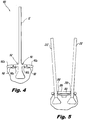
- Fig. 4 shows one blade 12 with an endwall portion 102a and an opposed endwall portion 102b extending laterally from the base portion of blade 12.
- Each endwall portion 102a forms an endwall with its adjacent endwall portion 102b of the adjacent blade 12.
- a small gap between adjacent endwall portions 102a and 102b is sealed by a seal 150.
- the endwall contours shown in Fig. 3 are formed in the combined surfaces of each matching pair of endwall portions 102a and 102b.
- the gap shown between adjacent endwall portions 102a and 102b in Fig. 4 is exaggerated for sake of clarity.
- the transition between the main portion of each blade 12 and its endwall portions can include a fillet 152.
- blades 212 do not include endwall portions. Instead, endwall segments 202 are provided between each adjacent pair of blades 212. Much like endwall portions 102a and 102b described above, the radially outward surface 208 of the body of each endwall segment 202 includes the contours as shown in Fig. 3 . Sealing is provided between the blades 212 and endwall segments 202, e.g., with rubber seals 250.
- the endwall contouring described herein can be used to reduce and control endwall vortex rollup coming off of the fan root inner diameter.
- the non-axisymmetric deflections or contours in the fan root platform generate a static pressure field that impacts the endwall vortex generation. This provides for an improved flow field profile entering the core and neutral or beneficial impact on engine TSFC (thrust specific fuel consumption).
- Figs. 4 and 5 show two exemplary endwall configurations, and those skilled in the art will readily appreciate that the contouring disclosed herein can be applied to any other suitable endwall configuration as well.
Landscapes
- Engineering & Computer Science (AREA)
- Mechanical Engineering (AREA)
- General Engineering & Computer Science (AREA)
- Physics & Mathematics (AREA)
- Fluid Mechanics (AREA)
- Structures Of Non-Positive Displacement Pumps (AREA)
Claims (5)
- Turbomaschine, umfassend:
eine Stirnwand (102) mit einer Vielzahl von in Umfangsrichtung beabstandeten, radial verlaufenden Schaufeln (12), die sich von der Stirnwand aus erstrecken, wobei eine erste der Schaufeln eine Druckfläche (104) eines Strömungskanals (106) definiert, eine zweite der Schaufeln eine Saugfläche (108) des Strömungskanals definiert und die Stirnwand eine Innenfläche des Strömungskanals definiert, und wobei die Stirnwand einen radial erhabenen Abschnitt, der nahe der Saugfläche erhaben ist, wobei der Scheitelpunkt des erhabenen Abschnitts näher an der Saugfläche (108) als an der Druckfläche (104) liegt, und einen radial vertieften Abschnitt stromabwärts des erhabenen Abschnitts beinhaltet, wobei sich der vertiefte Abschnitt axial durch den Strömungskanal (106) von einem Auslass des Kanals, der durch Hinterkanten (114) der Schaufeln (12) definiert wird, zu einem Punkt mehr als die Hälfte der Strecke stromaufwärts zu einem Einlass, der durch Vorderkanten (110) der Schaufeln definiert wird, erstreckt, wobei die Stirnwand (102) einen radial neutralen Abschnitt (112) zwischen dem Scheitelpunkt des erhabenen Abschnitts und der Druckfläche (104) beinhaltet, der einer Form eines nominalen achsensymmetrischen Strömungswegs entspricht, wobei der neutrale Abschnitt im Wesentlichen neutral in der radialen Erhebung ist, sich von der Druckfläche zu einem Punkt auf halbem Wege zwischen der Druckfläche und der Saugfläche (108) in Umfangsrichtung erstreckt, wobei der erhabene abschnitt axial in vollem Umfang zwischen dem Einlass und dem Auslass angeordnet ist. - Turbomaschine nach Anspruch 1, wobei der erhabene Abschnitt der Stirnwand (102) nahe einer Vorderkante (110) der Schaufel (12), die die Saugfläche (108) definiert, liegt.
- Turbomaschine nach einem der vorstehenden Ansprüche, wobei der vertiefte Abschnitt der Stirnwand (102) in Umfangsrichtung von der Druckfläche (104) zur Saugfläche (108) verläuft.
- Turbomaschine nach einem der vorstehenden Ansprüche, wobei die Turbomaschine ein Turbofan ist, der eine Fanbaugruppe umfasst, wobei die Fanschaufeln einen Fanschaufelabschnitt
und ein Paar gegenüberliegender Stirnwandabschnitte (102a; 102b) umfassen, die sich seitlich von dem Fanschaufelabschnitt aus erstrecken, wobei jeder Stirnwandabschnitt dazu konfiguriert ist, die Stirnwand mit einem in Umfangrichtung angrenzenden Stirnwandabschnitt zu bilden. - Turbomaschine nach Anspruch 4, wobei ein Spalt zwischen angrenzenden Stirnwandabschnitten (102a, 102b) durch eine Dichtung (150) abgedichtet wird.
Applications Claiming Priority (2)
| Application Number | Priority Date | Filing Date | Title |
|---|---|---|---|
| US201361878950P | 2013-09-17 | 2013-09-17 | |
| PCT/US2014/049368 WO2015041758A1 (en) | 2013-09-17 | 2014-08-01 | Fan root endwall contouring |
Publications (4)
| Publication Number | Publication Date |
|---|---|
| EP3047104A1 EP3047104A1 (de) | 2016-07-27 |
| EP3047104A4 EP3047104A4 (de) | 2017-07-05 |
| EP3047104B1 true EP3047104B1 (de) | 2021-03-03 |
| EP3047104B8 EP3047104B8 (de) | 2021-04-14 |
Family
ID=52689251
Family Applications (1)
| Application Number | Title | Priority Date | Filing Date |
|---|---|---|---|
| EP14845929.0A Active EP3047104B8 (de) | 2013-09-17 | 2014-08-01 | Turbomaschine mit wand-konturierung |
Country Status (3)
| Country | Link |
|---|---|
| US (1) | US10378360B2 (de) |
| EP (1) | EP3047104B8 (de) |
| WO (1) | WO2015041758A1 (de) |
Families Citing this family (9)
| Publication number | Priority date | Publication date | Assignee | Title |
|---|---|---|---|---|
| GB201420010D0 (en) | 2014-11-11 | 2014-12-24 | Rolls Royce Plc | Gas turbine engine |
| GB201420011D0 (en) | 2014-11-11 | 2014-12-24 | Rolls Royce Plc | Gas turbine engine |
| US10358922B2 (en) * | 2016-11-10 | 2019-07-23 | Rolls-Royce Corporation | Turbine wheel with circumferentially-installed inter-blade heat shields |
| US10865806B2 (en) | 2017-09-15 | 2020-12-15 | Pratt & Whitney Canada Corp. | Mistuned rotor for gas turbine engine |
| US11002293B2 (en) * | 2017-09-15 | 2021-05-11 | Pratt & Whitney Canada Corp. | Mistuned compressor rotor with hub scoops |
| US10443411B2 (en) | 2017-09-18 | 2019-10-15 | Pratt & Whitney Canada Corp. | Compressor rotor with coated blades |
| US10837459B2 (en) | 2017-10-06 | 2020-11-17 | Pratt & Whitney Canada Corp. | Mistuned fan for gas turbine engine |
| BE1025666B1 (fr) * | 2017-10-26 | 2019-05-27 | Safran Aero Boosters S.A. | Profil non-axisymetrique de carter pour compresseur turbomachine |
| US12442309B2 (en) * | 2019-09-12 | 2025-10-14 | General Electric Company | Nozzle assembly for turbine engine |
Citations (1)
| Publication number | Priority date | Publication date | Assignee | Title |
|---|---|---|---|---|
| US20060140768A1 (en) * | 2004-12-24 | 2006-06-29 | General Electric Company | Scalloped surface turbine stage |
Family Cites Families (13)
| Publication number | Priority date | Publication date | Assignee | Title |
|---|---|---|---|---|
| US5397215A (en) * | 1993-06-14 | 1995-03-14 | United Technologies Corporation | Flow directing assembly for the compression section of a rotary machine |
| US5836744A (en) | 1997-04-24 | 1998-11-17 | United Technologies Corporation | Frangible fan blade |
| US6561761B1 (en) * | 2000-02-18 | 2003-05-13 | General Electric Company | Fluted compressor flowpath |
| US7249933B2 (en) | 2005-01-10 | 2007-07-31 | General Electric Company | Funnel fillet turbine stage |
| GB0518628D0 (en) * | 2005-09-13 | 2005-10-19 | Rolls Royce Plc | Axial compressor blading |
| FR2926856B1 (fr) * | 2008-01-30 | 2013-03-29 | Snecma | Compresseur de turboreacteur |
| US8459956B2 (en) * | 2008-12-24 | 2013-06-11 | General Electric Company | Curved platform turbine blade |
| US8231353B2 (en) * | 2008-12-31 | 2012-07-31 | General Electric Company | Methods and apparatus relating to improved turbine blade platform contours |
| US8439643B2 (en) * | 2009-08-20 | 2013-05-14 | General Electric Company | Biformal platform turbine blade |
| ES2440563T3 (es) | 2011-02-08 | 2014-01-29 | MTU Aero Engines AG | Canal de álabe con contornos de pared lateral y correspondiente aparato de flujo |
| US8807930B2 (en) * | 2011-11-01 | 2014-08-19 | United Technologies Corporation | Non axis-symmetric stator vane endwall contour |
| US9194235B2 (en) * | 2011-11-25 | 2015-11-24 | Mtu Aero Engines Gmbh | Blading |
| EP3158167B1 (de) * | 2014-06-18 | 2020-10-07 | Siemens Energy, Inc. | Endwandkonfiguration für gasturbinenmotor |
-
2014
- 2014-08-01 EP EP14845929.0A patent/EP3047104B8/de active Active
- 2014-08-01 WO PCT/US2014/049368 patent/WO2015041758A1/en not_active Ceased
- 2014-08-01 US US15/022,836 patent/US10378360B2/en active Active
Patent Citations (1)
| Publication number | Priority date | Publication date | Assignee | Title |
|---|---|---|---|---|
| US20060140768A1 (en) * | 2004-12-24 | 2006-06-29 | General Electric Company | Scalloped surface turbine stage |
Also Published As
| Publication number | Publication date |
|---|---|
| EP3047104B8 (de) | 2021-04-14 |
| EP3047104A1 (de) | 2016-07-27 |
| US10378360B2 (en) | 2019-08-13 |
| US20160230562A1 (en) | 2016-08-11 |
| EP3047104A4 (de) | 2017-07-05 |
| WO2015041758A1 (en) | 2015-03-26 |
Similar Documents
| Publication | Publication Date | Title |
|---|---|---|
| EP3047104B1 (de) | Turbomaschine mit wand-konturierung | |
| US10648362B2 (en) | Spline for a turbine engine | |
| US10655495B2 (en) | Spline for a turbine engine | |
| US10577955B2 (en) | Airfoil assembly with a scalloped flow surface | |
| US11015453B2 (en) | Engine component with non-diffusing section | |
| EP3722556B1 (de) | Gasturbinenabschnitt umfassend eine nicht-achsensymmetrische endwandkonturierung mit hinterer mittelpassagenspitze | |
| EP3722555B1 (de) | Turbinenabschnitt umfassend nicht axialsymmetrische endwandkonturierung mit vorderer mittelpassagenspitze | |
| JP2010156335A (ja) | 改良型タービン翼プラットフォームの輪郭に関する方法および装置 | |
| US11852034B2 (en) | Tandem rotor blades | |
| EP2728196A2 (de) | Blutströmungskanal | |
| US20180340437A1 (en) | Spline for a turbine engine | |
| US20180355754A1 (en) | Spline for a turbine engine | |
| US20180355741A1 (en) | Spline for a turbine engine | |
| JP2017106452A (ja) | フィレットフィルム孔を有するガスタービンエンジン | |
| EP3392459A1 (de) | Verdichterschaufeln | |
| EP3064709A1 (de) | Gasturbinenschaufelplattform zur beeiflussung von verlusten durch heissgaseinzug | |
| CN106979177A (zh) | 涡轮压缩机导叶 | |
| US9664118B2 (en) | Method and system for controlling compressor forward leakage | |
| US11939880B1 (en) | Airfoil assembly with flow surface | |
| US8905716B2 (en) | Ladder seal system for gas turbine engines | |
| US20160130964A1 (en) | Gas turbine engine flow control device | |
| WO2018128609A1 (en) | Seal assembly between a hot gas path and a rotor disc cavity | |
| US12196087B2 (en) | Turbine engine with a rotating blade having a fin | |
| EP4144959A1 (de) | Strömungmaschine für ein flugzeugtriebwerk und flugzeugtriebwerk | |
| EP4144958A1 (de) | Strömungmaschine für ein flugzeugtriebwerk und flugzeugtriebwerk |
Legal Events
| Date | Code | Title | Description |
|---|---|---|---|
| PUAI | Public reference made under article 153(3) epc to a published international application that has entered the european phase |
Free format text: ORIGINAL CODE: 0009012 |
|
| 17P | Request for examination filed |
Effective date: 20160415 |
|
| AK | Designated contracting states |
Kind code of ref document: A1 Designated state(s): AL AT BE BG CH CY CZ DE DK EE ES FI FR GB GR HR HU IE IS IT LI LT LU LV MC MK MT NL NO PL PT RO RS SE SI SK SM TR |
|
| AX | Request for extension of the european patent |
Extension state: BA ME |
|
| RAP1 | Party data changed (applicant data changed or rights of an application transferred) |
Owner name: UNITED TECHNOLOGIES CORPORATION |
|
| DAX | Request for extension of the european patent (deleted) | ||
| A4 | Supplementary search report drawn up and despatched |
Effective date: 20170602 |
|
| RIC1 | Information provided on ipc code assigned before grant |
Ipc: F01D 5/14 20060101AFI20170529BHEP Ipc: F04D 29/38 20060101ALI20170529BHEP Ipc: F01D 5/30 20060101ALI20170529BHEP |
|
| STAA | Information on the status of an ep patent application or granted ep patent |
Free format text: STATUS: EXAMINATION IS IN PROGRESS |
|
| 17Q | First examination report despatched |
Effective date: 20190131 |
|
| GRAP | Despatch of communication of intention to grant a patent |
Free format text: ORIGINAL CODE: EPIDOSNIGR1 |
|
| STAA | Information on the status of an ep patent application or granted ep patent |
Free format text: STATUS: GRANT OF PATENT IS INTENDED |
|
| INTG | Intention to grant announced |
Effective date: 20200129 |
|
| GRAJ | Information related to disapproval of communication of intention to grant by the applicant or resumption of examination proceedings by the epo deleted |
Free format text: ORIGINAL CODE: EPIDOSDIGR1 |
|
| STAA | Information on the status of an ep patent application or granted ep patent |
Free format text: STATUS: EXAMINATION IS IN PROGRESS |
|
| INTC | Intention to grant announced (deleted) | ||
| GRAP | Despatch of communication of intention to grant a patent |
Free format text: ORIGINAL CODE: EPIDOSNIGR1 |
|
| STAA | Information on the status of an ep patent application or granted ep patent |
Free format text: STATUS: GRANT OF PATENT IS INTENDED |
|
| INTG | Intention to grant announced |
Effective date: 20200915 |
|
| GRAS | Grant fee paid |
Free format text: ORIGINAL CODE: EPIDOSNIGR3 |
|
| GRAA | (expected) grant |
Free format text: ORIGINAL CODE: 0009210 |
|
| STAA | Information on the status of an ep patent application or granted ep patent |
Free format text: STATUS: THE PATENT HAS BEEN GRANTED |
|
| AK | Designated contracting states |
Kind code of ref document: B1 Designated state(s): AL AT BE BG CH CY CZ DE DK EE ES FI FR GB GR HR HU IE IS IT LI LT LU LV MC MK MT NL NO PL PT RO RS SE SI SK SM TR |
|
| REG | Reference to a national code |
Ref country code: GB Ref legal event code: FG4D |
|
| REG | Reference to a national code |
Ref country code: AT Ref legal event code: REF Ref document number: 1367396 Country of ref document: AT Kind code of ref document: T Effective date: 20210315 Ref country code: CH Ref legal event code: EP |
|
| REG | Reference to a national code |
Ref country code: DE Ref legal event code: R081 Ref document number: 602014075429 Country of ref document: DE Owner name: RAYTHEON TECHNOLOGIES CORPORATION, FARMINGTON, US Free format text: FORMER OWNER: UNITED TECHNOLOGIES CORPORATION, FARMINGTON, CONN., US Ref country code: DE Ref legal event code: R081 Ref document number: 602014075429 Country of ref document: DE Owner name: RTX CORPORATION (N.D.GES.D. STAATES DELAWARE),, US Free format text: FORMER OWNER: UNITED TECHNOLOGIES CORPORATION, FARMINGTON, CONN., US |
|
| RAP2 | Party data changed (patent owner data changed or rights of a patent transferred) |
Owner name: RAYTHEON TECHNOLOGIES CORPORATION |
|
| REG | Reference to a national code |
Ref country code: DE Ref legal event code: R096 Ref document number: 602014075429 Country of ref document: DE |
|
| REG | Reference to a national code |
Ref country code: CH Ref legal event code: PK Free format text: BERICHTIGUNG B8 Ref country code: IE Ref legal event code: FG4D |
|
| REG | Reference to a national code |
Ref country code: LT Ref legal event code: MG9D |
|
| PG25 | Lapsed in a contracting state [announced via postgrant information from national office to epo] |
Ref country code: BG Free format text: LAPSE BECAUSE OF FAILURE TO SUBMIT A TRANSLATION OF THE DESCRIPTION OR TO PAY THE FEE WITHIN THE PRESCRIBED TIME-LIMIT Effective date: 20210603 Ref country code: NO Free format text: LAPSE BECAUSE OF FAILURE TO SUBMIT A TRANSLATION OF THE DESCRIPTION OR TO PAY THE FEE WITHIN THE PRESCRIBED TIME-LIMIT Effective date: 20210603 Ref country code: LT Free format text: LAPSE BECAUSE OF FAILURE TO SUBMIT A TRANSLATION OF THE DESCRIPTION OR TO PAY THE FEE WITHIN THE PRESCRIBED TIME-LIMIT Effective date: 20210303 Ref country code: FI Free format text: LAPSE BECAUSE OF FAILURE TO SUBMIT A TRANSLATION OF THE DESCRIPTION OR TO PAY THE FEE WITHIN THE PRESCRIBED TIME-LIMIT Effective date: 20210303 Ref country code: GR Free format text: LAPSE BECAUSE OF FAILURE TO SUBMIT A TRANSLATION OF THE DESCRIPTION OR TO PAY THE FEE WITHIN THE PRESCRIBED TIME-LIMIT Effective date: 20210604 Ref country code: HR Free format text: LAPSE BECAUSE OF FAILURE TO SUBMIT A TRANSLATION OF THE DESCRIPTION OR TO PAY THE FEE WITHIN THE PRESCRIBED TIME-LIMIT Effective date: 20210303 |
|
| REG | Reference to a national code |
Ref country code: NL Ref legal event code: MP Effective date: 20210303 |
|
| REG | Reference to a national code |
Ref country code: AT Ref legal event code: MK05 Ref document number: 1367396 Country of ref document: AT Kind code of ref document: T Effective date: 20210303 |
|
| PG25 | Lapsed in a contracting state [announced via postgrant information from national office to epo] |
Ref country code: PL Free format text: LAPSE BECAUSE OF FAILURE TO SUBMIT A TRANSLATION OF THE DESCRIPTION OR TO PAY THE FEE WITHIN THE PRESCRIBED TIME-LIMIT Effective date: 20210303 Ref country code: LV Free format text: LAPSE BECAUSE OF FAILURE TO SUBMIT A TRANSLATION OF THE DESCRIPTION OR TO PAY THE FEE WITHIN THE PRESCRIBED TIME-LIMIT Effective date: 20210303 Ref country code: RS Free format text: LAPSE BECAUSE OF FAILURE TO SUBMIT A TRANSLATION OF THE DESCRIPTION OR TO PAY THE FEE WITHIN THE PRESCRIBED TIME-LIMIT Effective date: 20210303 Ref country code: SE Free format text: LAPSE BECAUSE OF FAILURE TO SUBMIT A TRANSLATION OF THE DESCRIPTION OR TO PAY THE FEE WITHIN THE PRESCRIBED TIME-LIMIT Effective date: 20210303 |
|
| PG25 | Lapsed in a contracting state [announced via postgrant information from national office to epo] |
Ref country code: NL Free format text: LAPSE BECAUSE OF FAILURE TO SUBMIT A TRANSLATION OF THE DESCRIPTION OR TO PAY THE FEE WITHIN THE PRESCRIBED TIME-LIMIT Effective date: 20210303 |
|
| PG25 | Lapsed in a contracting state [announced via postgrant information from national office to epo] |
Ref country code: AT Free format text: LAPSE BECAUSE OF FAILURE TO SUBMIT A TRANSLATION OF THE DESCRIPTION OR TO PAY THE FEE WITHIN THE PRESCRIBED TIME-LIMIT Effective date: 20210303 Ref country code: EE Free format text: LAPSE BECAUSE OF FAILURE TO SUBMIT A TRANSLATION OF THE DESCRIPTION OR TO PAY THE FEE WITHIN THE PRESCRIBED TIME-LIMIT Effective date: 20210303 Ref country code: CZ Free format text: LAPSE BECAUSE OF FAILURE TO SUBMIT A TRANSLATION OF THE DESCRIPTION OR TO PAY THE FEE WITHIN THE PRESCRIBED TIME-LIMIT Effective date: 20210303 Ref country code: SM Free format text: LAPSE BECAUSE OF FAILURE TO SUBMIT A TRANSLATION OF THE DESCRIPTION OR TO PAY THE FEE WITHIN THE PRESCRIBED TIME-LIMIT Effective date: 20210303 |
|
| PG25 | Lapsed in a contracting state [announced via postgrant information from national office to epo] |
Ref country code: PT Free format text: LAPSE BECAUSE OF FAILURE TO SUBMIT A TRANSLATION OF THE DESCRIPTION OR TO PAY THE FEE WITHIN THE PRESCRIBED TIME-LIMIT Effective date: 20210705 Ref country code: ES Free format text: LAPSE BECAUSE OF FAILURE TO SUBMIT A TRANSLATION OF THE DESCRIPTION OR TO PAY THE FEE WITHIN THE PRESCRIBED TIME-LIMIT Effective date: 20210303 Ref country code: SK Free format text: LAPSE BECAUSE OF FAILURE TO SUBMIT A TRANSLATION OF THE DESCRIPTION OR TO PAY THE FEE WITHIN THE PRESCRIBED TIME-LIMIT Effective date: 20210303 Ref country code: RO Free format text: LAPSE BECAUSE OF FAILURE TO SUBMIT A TRANSLATION OF THE DESCRIPTION OR TO PAY THE FEE WITHIN THE PRESCRIBED TIME-LIMIT Effective date: 20210303 Ref country code: IS Free format text: LAPSE BECAUSE OF FAILURE TO SUBMIT A TRANSLATION OF THE DESCRIPTION OR TO PAY THE FEE WITHIN THE PRESCRIBED TIME-LIMIT Effective date: 20210703 |
|
| REG | Reference to a national code |
Ref country code: DE Ref legal event code: R097 Ref document number: 602014075429 Country of ref document: DE |
|
| PLBE | No opposition filed within time limit |
Free format text: ORIGINAL CODE: 0009261 |
|
| STAA | Information on the status of an ep patent application or granted ep patent |
Free format text: STATUS: NO OPPOSITION FILED WITHIN TIME LIMIT |
|
| PG25 | Lapsed in a contracting state [announced via postgrant information from national office to epo] |
Ref country code: DK Free format text: LAPSE BECAUSE OF FAILURE TO SUBMIT A TRANSLATION OF THE DESCRIPTION OR TO PAY THE FEE WITHIN THE PRESCRIBED TIME-LIMIT Effective date: 20210303 Ref country code: AL Free format text: LAPSE BECAUSE OF FAILURE TO SUBMIT A TRANSLATION OF THE DESCRIPTION OR TO PAY THE FEE WITHIN THE PRESCRIBED TIME-LIMIT Effective date: 20210303 |
|
| 26N | No opposition filed |
Effective date: 20211206 |
|
| PG25 | Lapsed in a contracting state [announced via postgrant information from national office to epo] |
Ref country code: SI Free format text: LAPSE BECAUSE OF FAILURE TO SUBMIT A TRANSLATION OF THE DESCRIPTION OR TO PAY THE FEE WITHIN THE PRESCRIBED TIME-LIMIT Effective date: 20210303 |
|
| REG | Reference to a national code |
Ref country code: CH Ref legal event code: PL |
|
| PG25 | Lapsed in a contracting state [announced via postgrant information from national office to epo] |
Ref country code: MC Free format text: LAPSE BECAUSE OF FAILURE TO SUBMIT A TRANSLATION OF THE DESCRIPTION OR TO PAY THE FEE WITHIN THE PRESCRIBED TIME-LIMIT Effective date: 20210303 |
|
| REG | Reference to a national code |
Ref country code: BE Ref legal event code: MM Effective date: 20210831 |
|
| PG25 | Lapsed in a contracting state [announced via postgrant information from national office to epo] |
Ref country code: LI Free format text: LAPSE BECAUSE OF NON-PAYMENT OF DUE FEES Effective date: 20210831 Ref country code: IT Free format text: LAPSE BECAUSE OF FAILURE TO SUBMIT A TRANSLATION OF THE DESCRIPTION OR TO PAY THE FEE WITHIN THE PRESCRIBED TIME-LIMIT Effective date: 20210303 Ref country code: CH Free format text: LAPSE BECAUSE OF NON-PAYMENT OF DUE FEES Effective date: 20210831 |
|
| PG25 | Lapsed in a contracting state [announced via postgrant information from national office to epo] |
Ref country code: IS Free format text: LAPSE BECAUSE OF FAILURE TO SUBMIT A TRANSLATION OF THE DESCRIPTION OR TO PAY THE FEE WITHIN THE PRESCRIBED TIME-LIMIT Effective date: 20210703 Ref country code: LU Free format text: LAPSE BECAUSE OF NON-PAYMENT OF DUE FEES Effective date: 20210801 |
|
| PG25 | Lapsed in a contracting state [announced via postgrant information from national office to epo] |
Ref country code: IE Free format text: LAPSE BECAUSE OF NON-PAYMENT OF DUE FEES Effective date: 20210801 Ref country code: BE Free format text: LAPSE BECAUSE OF NON-PAYMENT OF DUE FEES Effective date: 20210831 |
|
| PG25 | Lapsed in a contracting state [announced via postgrant information from national office to epo] |
Ref country code: HU Free format text: LAPSE BECAUSE OF FAILURE TO SUBMIT A TRANSLATION OF THE DESCRIPTION OR TO PAY THE FEE WITHIN THE PRESCRIBED TIME-LIMIT; INVALID AB INITIO Effective date: 20140801 |
|
| P01 | Opt-out of the competence of the unified patent court (upc) registered |
Effective date: 20230520 |
|
| PG25 | Lapsed in a contracting state [announced via postgrant information from national office to epo] |
Ref country code: CY Free format text: LAPSE BECAUSE OF FAILURE TO SUBMIT A TRANSLATION OF THE DESCRIPTION OR TO PAY THE FEE WITHIN THE PRESCRIBED TIME-LIMIT Effective date: 20210303 |
|
| PG25 | Lapsed in a contracting state [announced via postgrant information from national office to epo] |
Ref country code: MK Free format text: LAPSE BECAUSE OF FAILURE TO SUBMIT A TRANSLATION OF THE DESCRIPTION OR TO PAY THE FEE WITHIN THE PRESCRIBED TIME-LIMIT Effective date: 20210303 |
|
| PG25 | Lapsed in a contracting state [announced via postgrant information from national office to epo] |
Ref country code: MT Free format text: LAPSE BECAUSE OF FAILURE TO SUBMIT A TRANSLATION OF THE DESCRIPTION OR TO PAY THE FEE WITHIN THE PRESCRIBED TIME-LIMIT Effective date: 20210303 |
|
| REG | Reference to a national code |
Ref country code: DE Ref legal event code: R081 Ref document number: 602014075429 Country of ref document: DE Owner name: RTX CORPORATION (N.D.GES.D. STAATES DELAWARE),, US Free format text: FORMER OWNER: RAYTHEON TECHNOLOGIES CORPORATION, FARMINGTON, CT, US |
|
| PGFP | Annual fee paid to national office [announced via postgrant information from national office to epo] |
Ref country code: DE Payment date: 20250724 Year of fee payment: 12 |
|
| PGFP | Annual fee paid to national office [announced via postgrant information from national office to epo] |
Ref country code: GB Payment date: 20250724 Year of fee payment: 12 |
|
| PGFP | Annual fee paid to national office [announced via postgrant information from national office to epo] |
Ref country code: FR Payment date: 20250725 Year of fee payment: 12 |
|
| PG25 | Lapsed in a contracting state [announced via postgrant information from national office to epo] |
Ref country code: TR Free format text: LAPSE BECAUSE OF FAILURE TO SUBMIT A TRANSLATION OF THE DESCRIPTION OR TO PAY THE FEE WITHIN THE PRESCRIBED TIME-LIMIT Effective date: 20210303 |