EP3047780A1 - Dispositif de cyclonage, collecteur de poussière, dispositif de nettoyage de surface et procédé de cyclonage - Google Patents
Dispositif de cyclonage, collecteur de poussière, dispositif de nettoyage de surface et procédé de cyclonage Download PDFInfo
- Publication number
- EP3047780A1 EP3047780A1 EP14893387.2A EP14893387A EP3047780A1 EP 3047780 A1 EP3047780 A1 EP 3047780A1 EP 14893387 A EP14893387 A EP 14893387A EP 3047780 A1 EP3047780 A1 EP 3047780A1
- Authority
- EP
- European Patent Office
- Prior art keywords
- cyclonic
- longitudinal axis
- dust
- separating device
- cyclonic separating
- Prior art date
- Legal status (The legal status is an assumption and is not a legal conclusion. Google has not performed a legal analysis and makes no representation as to the accuracy of the status listed.)
- Withdrawn
Links
Images



Classifications
-
- A—HUMAN NECESSITIES
- A47—FURNITURE; DOMESTIC ARTICLES OR APPLIANCES; COFFEE MILLS; SPICE MILLS; SUCTION CLEANERS IN GENERAL
- A47L—DOMESTIC WASHING OR CLEANING; SUCTION CLEANERS IN GENERAL
- A47L9/00—Details or accessories of suction cleaners, e.g. mechanical means for controlling the suction or for effecting pulsating action; Storing devices specially adapted to suction cleaners or parts thereof; Carrying-vehicles specially adapted for suction cleaners
- A47L9/10—Filters; Dust separators; Dust removal; Automatic exchange of filters
- A47L9/16—Arrangement or disposition of cyclones or other devices with centrifugal action
- A47L9/1616—Multiple arrangement thereof
-
- A—HUMAN NECESSITIES
- A47—FURNITURE; DOMESTIC ARTICLES OR APPLIANCES; COFFEE MILLS; SPICE MILLS; SUCTION CLEANERS IN GENERAL
- A47L—DOMESTIC WASHING OR CLEANING; SUCTION CLEANERS IN GENERAL
- A47L9/00—Details or accessories of suction cleaners, e.g. mechanical means for controlling the suction or for effecting pulsating action; Storing devices specially adapted to suction cleaners or parts thereof; Carrying-vehicles specially adapted for suction cleaners
- A47L9/10—Filters; Dust separators; Dust removal; Automatic exchange of filters
- A47L9/16—Arrangement or disposition of cyclones or other devices with centrifugal action
- A47L9/1608—Cyclonic chamber constructions
-
- A—HUMAN NECESSITIES
- A47—FURNITURE; DOMESTIC ARTICLES OR APPLIANCES; COFFEE MILLS; SPICE MILLS; SUCTION CLEANERS IN GENERAL
- A47L—DOMESTIC WASHING OR CLEANING; SUCTION CLEANERS IN GENERAL
- A47L9/00—Details or accessories of suction cleaners, e.g. mechanical means for controlling the suction or for effecting pulsating action; Storing devices specially adapted to suction cleaners or parts thereof; Carrying-vehicles specially adapted for suction cleaners
- A47L9/10—Filters; Dust separators; Dust removal; Automatic exchange of filters
- A47L9/16—Arrangement or disposition of cyclones or other devices with centrifugal action
- A47L9/1616—Multiple arrangement thereof
- A47L9/1625—Multiple arrangement thereof for series flow
- A47L9/1633—Concentric cyclones
-
- A—HUMAN NECESSITIES
- A47—FURNITURE; DOMESTIC ARTICLES OR APPLIANCES; COFFEE MILLS; SPICE MILLS; SUCTION CLEANERS IN GENERAL
- A47L—DOMESTIC WASHING OR CLEANING; SUCTION CLEANERS IN GENERAL
- A47L9/00—Details or accessories of suction cleaners, e.g. mechanical means for controlling the suction or for effecting pulsating action; Storing devices specially adapted to suction cleaners or parts thereof; Carrying-vehicles specially adapted for suction cleaners
- A47L9/10—Filters; Dust separators; Dust removal; Automatic exchange of filters
- A47L9/16—Arrangement or disposition of cyclones or other devices with centrifugal action
- A47L9/1616—Multiple arrangement thereof
- A47L9/1641—Multiple arrangement thereof for parallel flow
-
- A—HUMAN NECESSITIES
- A47—FURNITURE; DOMESTIC ARTICLES OR APPLIANCES; COFFEE MILLS; SPICE MILLS; SUCTION CLEANERS IN GENERAL
- A47L—DOMESTIC WASHING OR CLEANING; SUCTION CLEANERS IN GENERAL
- A47L9/00—Details or accessories of suction cleaners, e.g. mechanical means for controlling the suction or for effecting pulsating action; Storing devices specially adapted to suction cleaners or parts thereof; Carrying-vehicles specially adapted for suction cleaners
- A47L9/10—Filters; Dust separators; Dust removal; Automatic exchange of filters
- A47L9/16—Arrangement or disposition of cyclones or other devices with centrifugal action
- A47L9/165—Construction of inlets
-
- A—HUMAN NECESSITIES
- A47—FURNITURE; DOMESTIC ARTICLES OR APPLIANCES; COFFEE MILLS; SPICE MILLS; SUCTION CLEANERS IN GENERAL
- A47L—DOMESTIC WASHING OR CLEANING; SUCTION CLEANERS IN GENERAL
- A47L9/00—Details or accessories of suction cleaners, e.g. mechanical means for controlling the suction or for effecting pulsating action; Storing devices specially adapted to suction cleaners or parts thereof; Carrying-vehicles specially adapted for suction cleaners
- A47L9/10—Filters; Dust separators; Dust removal; Automatic exchange of filters
- A47L9/16—Arrangement or disposition of cyclones or other devices with centrifugal action
- A47L9/1658—Construction of outlets
- A47L9/1666—Construction of outlets with filtering means
-
- A—HUMAN NECESSITIES
- A47—FURNITURE; DOMESTIC ARTICLES OR APPLIANCES; COFFEE MILLS; SPICE MILLS; SUCTION CLEANERS IN GENERAL
- A47L—DOMESTIC WASHING OR CLEANING; SUCTION CLEANERS IN GENERAL
- A47L9/00—Details or accessories of suction cleaners, e.g. mechanical means for controlling the suction or for effecting pulsating action; Storing devices specially adapted to suction cleaners or parts thereof; Carrying-vehicles specially adapted for suction cleaners
- A47L9/10—Filters; Dust separators; Dust removal; Automatic exchange of filters
- A47L9/16—Arrangement or disposition of cyclones or other devices with centrifugal action
- A47L9/1683—Dust collecting chambers; Dust collecting receptacles
-
- B—PERFORMING OPERATIONS; TRANSPORTING
- B01—PHYSICAL OR CHEMICAL PROCESSES OR APPARATUS IN GENERAL
- B01D—SEPARATION
- B01D45/00—Separating dispersed particles from gases or vapours by gravity, inertia, or centrifugal forces
- B01D45/04—Separating dispersed particles from gases or vapours by gravity, inertia, or centrifugal forces by utilising inertia
- B01D45/08—Separating dispersed particles from gases or vapours by gravity, inertia, or centrifugal forces by utilising inertia by impingement against baffle separators
-
- B—PERFORMING OPERATIONS; TRANSPORTING
- B01—PHYSICAL OR CHEMICAL PROCESSES OR APPARATUS IN GENERAL
- B01D—SEPARATION
- B01D45/00—Separating dispersed particles from gases or vapours by gravity, inertia, or centrifugal forces
- B01D45/12—Separating dispersed particles from gases or vapours by gravity, inertia, or centrifugal forces by centrifugal forces
-
- B—PERFORMING OPERATIONS; TRANSPORTING
- B01—PHYSICAL OR CHEMICAL PROCESSES OR APPARATUS IN GENERAL
- B01D—SEPARATION
- B01D45/00—Separating dispersed particles from gases or vapours by gravity, inertia, or centrifugal forces
- B01D45/12—Separating dispersed particles from gases or vapours by gravity, inertia, or centrifugal forces by centrifugal forces
- B01D45/16—Separating dispersed particles from gases or vapours by gravity, inertia, or centrifugal forces by centrifugal forces generated by the winding course of the gas stream, the centrifugal forces being generated solely or partly by mechanical means, e.g. fixed swirl vanes
-
- B—PERFORMING OPERATIONS; TRANSPORTING
- B01—PHYSICAL OR CHEMICAL PROCESSES OR APPARATUS IN GENERAL
- B01D—SEPARATION
- B01D50/00—Combinations of methods or devices for separating particles from gases or vapours
- B01D50/20—Combinations of devices covered by groups B01D45/00 and B01D46/00
Definitions
- the present disclosure relates to the field of cleaning, and more particularly to a cyclonic separating device, a cleaner and a surface cleaning apparatus, as well as a method for separating dust from a dust containing air using the cyclonic separating device.
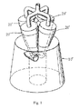
- FIG. 1 discloses an apparatus for separating particles from a fluid stream.
- the apparatus includes one upstream cyclonic separating device 10' and a plurality of downstream cyclonic separating devices 20' arranged in parallel with each other, and each downstream cyclonic separating device 20' is at least partially extended into an interior of the upstream cyclonic separating device 10'.
- the apparatus for separating particles from the fluid stream generally has a large height, a large volume, and a low separation efficiency.
- Embodiments of the present disclosure seek to solve at least one of the problems existing in the related art to at least some extent.
- the present disclosure provides a cyclonic separating device, which is simple to assemble, convenient to replace, and high in separation efficiency.
- the present disclosure needs to provide a cleaner having the cyclonic separating device.
- the present disclosure needs to provide a surface cleaning apparatus having an improved dust collecting space.
- the present disclosure needs to provide a method for separating dust from a dust containing air using the cyclonic separating device, which has high separation efficiency.
- a cyclonic separating device includes: a first cyclonic separator defining a first longitudinal axis; a plurality of second cyclonic separators located downstream of the first cyclonic separator, arranged circumferentially around the first longitudinal axis in parallel, and integrally received in the first cyclonic separator; an inlet passage at least partially received in the first cyclonic separator; a guiding passage communicated with the inlet passage and the first cyclonic separator respectively, in which a fluid introduced through the inlet passage is tangentially guided into the first cyclonic separator by the guiding passage.
- the overall height of the cyclonic separating device may be reduced, thus reducing the volume of the surface cleaning apparatus.
- the height of the entire dust barrel may be made use of to perform the primary separation of the fluid sufficiently, thus enhancing the separation efficiency of dust.
- cyclonic separating device may also have the following additional technical features.
- a fluid outlet of the guiding passage is disposed between two adjacent second cyclonic separators.
- a portion of the inlet passage received in the first cyclonic separator is extended along the first longitudinal axis.
- the fluid outlet is configured such that the fluid tangentially flows into the first cyclonic separator in a plane perpendicular to the first longitudinal axis.
- a projection of the guiding passage in the plane perpendicular to the first longitudinal axis is substantially helical or arc-shaped.
- At least one of the plurality of second cyclonic separators defines a second longitudinal axis parallel to the first longitudinal axis.
- the cyclonic separating device further includes: a dust collecting space surrounding a periphery of the inlet passage, and communicated with the plurality of second cyclonic separators respectively to collect dust separated by the plurality of second cyclonic separators.
- a central axis of the dust collecting space coincides with the first longitudinal axis.
- the cyclonic separating device further includes: a filtering member connected between adjacent second cyclonic separators, in which the fluid from which the dust has been separated by the first cyclonic separator tangentially flows into the second cyclonic separator via the filtering member.
- the filtering member and the adjacent second cyclonic separators are formed integrally.
- a central axis of the filtering member coincides with the first longitudinal axis, and a projection region of at least one of the plurality of second cyclonic separators in a plane perpendicular to the first longitudinal axis is protruded beyond a projection region of the filtering member in the plane perpendicular to the first longitudinal axis.
- a circumferential flanged edge is formed at a lower part of the filtering member, extended into the first cyclonic separator and inclined downwardly.
- a surface cleaning apparatus includes: a dust barrel defining an opening in an upper end thereof and an air intake therein; a cyclonic separating device disposed in the dust barrel, and including: a first cyclonic separator defining a first longitudinal axis, a portion of the first cyclonic separator being constituted by an inner wall of the dust barrel; a plurality of second cyclonic separators located downstream of the first cyclonic separator, arranged circumferentially around the first longitudinal axis in parallel, and integrally received in the first cyclonic separator; an inlet passage communicated with the air intake and at least partially received in the first cyclonic separator; a guiding passage communicated with the inlet passage and the first cyclonic separator respectively, in which a fluid introduced through the inlet passage is tangentially guided into the first cyclonic separator by the guiding passage; and a dust collecting chamber located below the cyclonic separating device in the dust barrel to collect dust in the fluid separated by the cyclonic
- the overall height of the cyclonic separating device may be reduced, thus reducing the volume of the surface cleaning apparatus.
- the height of the entire dust barrel may be made use of to perform the primary separation of the fluid sufficiently, thus enhancing the separation efficiency of dust.
- a method for separating dust from a dust containing air using the abovementioned cyclonic separating device includes steps of: introducing the dust containing air into the cyclonic separating device via the inlet passage; tangentially introducing the dust containing air into the first cyclonic separator for primary separation; tangentially introducing the dust containing air from which a dust has been separated primarily by the first cyclonic separator into the plurality of second cyclonic separators respectively for secondary separation; and introducing dust separated from the dust containing air into a dust collecting chamber located below the cyclonic separating device.
- the overall height of the cyclonic separating device may be made full use of to perform the primary separation and secondary separation of the dust containing air, thus enhancing the separation efficiency of the cyclonic separating device.
- first and second are used herein for purposes of description and are not intended to indicate or imply relative importance or significance or to imply the number of indicated technical features.
- the feature defined with “first” and “second” may comprise one or more of this feature.
- a plurality of means two or more than two, unless specified otherwise.
- the terms “mounted,” “connected,” “coupled,” “fixed” and the like are used broadly, and may be, for example, fixed connections, detachable connections, or integral connections; may also be mechanical or electrical connections; may also be direct connections or indirect connections via intervening structures; may also be inner communications of two elements, which can be understood by those skilled in the art according to specific situations.
- a structure in which a first feature is "on" or “below” a second feature may include an embodiment in which the first feature is in direct contact with the second feature, and may also include an embodiment in which the first feature and the second feature are not in direct contact with each other, but are contacted via an additional feature formed therebetween.
- a first feature "on,” “above,” or “on top of” a second feature may include an embodiment in which the first feature is right or obliquely “on,” “above,” or “on top of” the second feature, or just means that the first feature is at a height higher than that of the second feature; while a first feature “below,” “under,” or “on bottom of” a second feature may include an embodiment in which the first feature is right or obliquely “below,” “under,” or “on bottom of” the second feature, or just means that the first feature is at a height lower than that of the second feature.
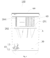
- Figs. 2-6 show a part of a surface cleaning apparatus 100.
- the surface cleaning apparatus 100 may be a cleaner, such as a vertical cleaner or a horizontal cleaner.
- Figs. 2-6 show a part of a dust barrel of a vertical cleaner.
- the surface cleaning apparatus 100 may include a dust barrel 10, a cyclonic separating device 20, and a dust collecting chamber 30.
- the dust barrel 10 defining an opening 101 in an upper end thereof and an air intake 11 therein.
- a stream containing dust is introduced into the dust barrel 10 via the air intake 11, and then the dust is separated from the stream in the dust barrel 10.
- a barrel cover 50 may be disposed at the opening 101, through holes 51 are formed in the barrel cover 50, and the cleaned stream may be discharged from the through holes 51.
- the air intake 11 may be connected with a sucking component (not shown) of the surface cleaning apparatus 100.
- the sucking component may be a floor brush assembly or a suction head of a cleaner.
- the cyclonic separating device 20 may include a first cyclonic separator 201, a plurality of second cyclonic separators 202, an inlet passage 203 and a guiding passage 204.
- the first cyclonic separator 201 may define a first longitudinal axis, and a portion of the first cyclonic separator 201 is constituted by an inner wall of the dust barrel 10, as shown in Fig. 3 .
- a first cyclonic separating space A for cleaning and separating the stream needs to be configured in the dust barrel 10 with the aid of the inner wall of the dust barrel 10, and the first cyclonic separating space A may be used as a primary separation portion of the cyclonic separating device 20 for performing primary separation on the stream entering the cyclonic separating device 20, such that large particles or dust may be separated from the stream.
- the plurality of second cyclonic separators 202 are located downstream of the first cyclonic separator 201, arranged circumferentially around the first longitudinal axis in parallel, and integrally received in the first cyclonic separator 201.
- the inlet passage 203 is at least partially received in the first cyclonic separator 201 and separated from the first cyclonic separator 201.
- the guiding passage 204 is communicated with the inlet passage 203 and the first cyclonic separator 201 respectively, and a fluid introduced through the inlet passage 203 is tangentially guided into the first cyclonic separator 201 by the guiding passage 204.
- the inlet passage 203 is communicated with the air intake 11.
- one end of the inlet passage 203 is communicated with the air intake 11, the other end of the inlet passage 203 is communicated with one end of the guiding passage 204, the other end of the inlet passage 203 is communicated with the first cyclonic separating space A, and the stream guided out of the guiding passage 204 enters into the first cyclonic separating space A in a tangential direction realizing the cleaning and separating in the first cyclonic separating space A.
- the dust collecting chamber 30 may be located below the cyclonic separating device 20 in the dust barrel 10 to collect dust in the fluid separated by the cyclonic separating device 20, as shown in Fig. 2 .
- the dust collecting chamber 30 may be used for collecting dust separated by the first cyclonic separator 201 and/or the second cyclonic separators 202.
- the stream is introduced into the first cyclonic separating space A via the guiding passage 204. After the cleaning and separating are completed, the cleaned stream enters into the plurality of second cyclonic separators 202 for secondary cleaning and separating. After the secondary cleaning and separating is performed in the second cyclonic separators 202, the stream is discharged via the through holes 51.
- the primarily cleaned stream may be dispersed and enters into the plurality of second cyclonic separators 202 in parallel, such that the cyclonic separating may be completed in the plurality of second cyclonic separators 202 respectively.
- the surface cleaning apparatus 100 since the plurality of second cyclonic separators 202 are integrally received in the first cyclonic separator 201 and the height of the cyclonic separating device 20 only corresponds to the height of the first cyclonic separator 201, the overall height of the cyclonic separating device 20 may be reduced, thus reducing the volume of the surface cleaning apparatus 100.
- the plurality of second cyclonic separators 202 in parallel are located in the first cyclonic separator 201, for example, the height of the entire dust barrel may be made use of to perform the primary separation of the fluid sufficiently, thus enhancing the separation efficiency of dust.
- the inlet passage 203 and the second cyclonic separators 202 may be integrally molded, thus reducing the number of components of the surface cleaning apparatus 100 to be assembled, decreasing the number of times of opening a mould, and lowering the production cost.
- a fluid outlet 2041 of the guiding passage 204 is disposed between two adjacent second cyclonic separators 202, such that the stream may enter into the first cyclonic separating space A conveniently.
- a portion of the inlet passage 203 received in the first cyclonic separator 201 is extended along the first longitudinal axis.
- the fluid outlet 2041 is configured such that the fluid tangentially flows into the first cyclonic separator 201 in a plane perpendicular to the first longitudinal axis.
- the fluid outlet 2041 is configured to be in a horizontal direction, and the stream enters into the first cyclonic separator 201 in the horizontal direction.
- the stream tangentially enters into the first cyclonic separator 201 and the fluid outlet 2041 is located between two adjacent second cyclonic separators 202 the stream flowing upwardly from a bottom of the dust barrel may be sufficiently separated in a circumferential direction, and then enters into the second cyclonic separators 202 for cyclonic separating.
- a dust receiving space located in the bottom of the dust barrel may be significantly increased, and the dust receiving volume actually used by the inventors is increased by more than 70% compared to the volume of a conventional surface cleaning apparatus shown in e.g., Fig. 1 .
- a projection of the guiding passage 204 in the plane perpendicular to the first longitudinal axis is substantially helical or arc-shaped. Therefore, the fluid outlet 2041 is conveniently configured such that the fluid tangentially is introduced into the first cyclonic separator 201 in the tangential direction. Still further, in one embodiment, at least one of the plurality of second cyclonic separators 202 defines a second longitudinal axis parallel to the first longitudinal axis.
- the surface cleaning apparatus 100 further includes a dust collecting space 40 surrounding a periphery of the inlet passage 203, and communicated with the plurality of second cyclonic separators 202 respectively to collect dust separated by the plurality of second cyclonic separators 202.
- the dust collecting space 40 may be formed in an interior of the dust barrel 10, and located in a circular space in the dust collecting chamber 30.
- the dust collecting space 40 may be used for collecting dust separated by the plurality of second cyclonic separators 202 arranged circumferentially. It would be appreciated that the dust collecting space 40 may be defined by an annular portion at a lower part of the first cyclonic separator 201 and the inlet passage 203 which are molded integrally.
- the surface cleaning apparatus 100 may further include a filtering member 60.
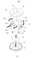
- the filtering member 60 is connected between adjacent second cyclonic separators 202, in which the fluid from which the dust has been separated by the first cyclonic separator 201 tangentially flows into the second cyclonic separator 202 via the filtering member 60, as shown in Fig. 6 .
- a plurality of holes 61 disposed correspondingly to inlets of the plurality of second cyclonic separators 202 are formed in the filtering member 60.
- the filtering member 60 it is possible to prevent large dust from entering into the second cyclonic separator 202 via the inlet of the second cyclonic separator 202 directly, and to separate the large dust in the first cyclonic separating space A and introduce the large dust in the dust collecting chamber 30.
- the filtering member 60 and the adjacent second cyclonic separators 202 are formed integrally, thus reducing the number of times of opening the mould and the assembly cost.
- a central axis of the filtering member 60 coincides with the first longitudinal axis, and a projection region of at least one of the plurality of second cyclonic separators 202 in a plane perpendicular to the first longitudinal axis is protruded beyond a projection region of the filtering member 60 in the plane perpendicular to the first longitudinal axis.
- the filtering member 60 connected between two second cyclonic separators 202 may be arc-shaped, and an outer end of the filtering member 60 may be located within outer ends of two adjacent second cyclonic separators 202.
- a circumferential flanged edge 70 is formed at a lower part of the filtering member 60, extended into the first cyclonic separator 201 and inclined downwardly.
- the circumferential flanged edge 70 may prevent dust separated by the first cyclonic separator 201 from rising.
- at least one of the plurality of second cyclonic separators 202 defines the second longitudinal axis parallel to the first longitudinal axis.
- the plurality of second cyclonic separators 202 and the first cyclonic separator 201 may be disposed in parallel with each other, thus enhancing the separation efficiency of the cyclonic separating device 20.
- the dust barrel 10 may include a barrel bottom 12 and a barrel body 13. Specifically, the air intake 11 is formed at a central position of the barrel bottom 12 of the dust barrel 10, and the inlet passage 203 is communicated with the air intake 11.
- the barrel body 13 is detachably connected to the barrel bottom 12.
- the dust barrel 10 may be convenient to disassemble and assemble, and convenient to use.
- the surface cleaning apparatus 100 may further include a barrel cover 50.
- the barrel cover 50 is disposed at an upper end of the dust barrel 10 to close the opening 101, through holes 51 communicated with the plurality of second cyclonic separators 202 (e.g., communicated with air outlets of the second cyclonic separators 202) are formed in the barrel cover 50 to discharge the fluid from which the dust has been separated by the plurality of second cyclonic separators 202.
- a block piece 52 is disposed in the through hole 50, and is parallel to the first longitudinal axis. Thus, the block piece 52 may perform a certain guidance function to guide the stream blown out from the outlet of the second cyclonic separator 202 to discharge upwardly, such that the cleaned stream may be discharged more stably.
- an air guiding member 53 is disposed at a side of the barrel cover 50 facing the opening 101, is snap-fitted with an indentation 54 of the second cyclonic separator 202 facing the barrel cover 50, and forms an air inlet of the second cyclonic separator 202. Since the air guiding member 53 is snap-fitted with the second cyclonic separator 202, by means of the snap-fitting between the air guiding member 53 on the barrel cover 50 and the indentation 54 of the second cyclonic separator 202, the cyclonic separating device 20 may be positioned in the dust barrel 10, thus enhancing the stability of the surface cleaning apparatus 100 in use.
- a plurality of splitters 91 are formed on the barrel bottom 12, and radially extended toward the first longitudinal axis in a plane through which the first longitudinal axis penetrates.
- the splitters 91 are located in the plane through which the first longitudinal axis penetrates respectively.
- the splitters 91 may divide the bottom of the dust barrel 10 into a plurality of spaces spaced apart from each other, such that it is possible to prevent swirls from being generated at the bottom of the dust barrel 10, and to restrict dust within the plurality of spaces spaced apart from each other.
- air disturbing fins 92 are formed on a portion of an inner side wall of the barrel body 13 adjacent to the barrel bottom 12, and extended toward the first longitudinal axis in the plane through which the first longitudinal axis penetrates, thus further preventing swirls from being generated at the bottom of the dust barrel 10.
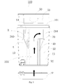
- the stream sucked by the surface cleaning apparatus 100 first enters into the inlet passage 203 via the air intake 11, and enters into the first cyclonic separating space A via the guiding passage 204.
- the stream advances upwardly to the filtering member 60, passes through the filtering member 60 and enters into the plurality of second cyclonic separators 202 in the tangential direction.
- the stream is discharged from the through holes 51 in the barrel cover 50. Dust separated by the first cyclonic separator 201 is stored in the dust collecting chamber 30, and dust separated by the second cyclonic separators 202 are stored in the dust collecting space 40.
- the cyclonic separating device 20 may be the cyclonic separating device of the surface cleaning apparatus 100 in the above embodiments.
- the cyclonic separating device 20 may include a first cyclonic separating space A, a plurality of second cyclonic separating spaces B, an inlet passage 203 and a guiding passage 204.
- the first cyclonic separating space A defines a first longitudinal axis.
- the plurality of second cyclonic separating spaces B are located downstream of the first cyclonic separating space A, arranged circumferentially around the first longitudinal axis in parallel, and integrally received in the first cyclonic separating space A.
- the inlet passage 203 is at least partially received in the first cyclonic separating space A.
- the guiding passage 204 is communicated with the inlet passage 203 and the first cyclonic separating space A respectively, and a fluid introduced through the inlet passage 203 is tangentially guided into the first cyclonic separating space A by the guiding passage 204.
- the cyclonic separating device 20 since the plurality of second cyclonic separating spaces B are integrally received in the first cyclonic separating space A and the height of the cyclonic separating device 20 only corresponds to the height of the first cyclonic separating space A, the overall height of the cyclonic separating device 20 may be reduced, thus reducing the volume of the surface cleaning apparatus.
- the plurality of second cyclonic separating spaces B in parallel are located in the first cyclonic separating space A, for example, the height of the entire dust barrel 10 may be made use of to perform the primary separation of the fluid sufficiently, thus enhancing the separation efficiency of dust.
- the overall height of the cyclonic separating device 20 may be reduced, thus reducing the volume of the surface cleaning apparatus 100. Meanwhile, since the second cyclonic separating spaces B are located within the first cyclonic separating space A, the height of the second cyclonic separating spaces B may be increased, such that the cyclonic separating device 20 may have a higher separation efficiency, and the operation efficiency of the surface cleaning apparatus 100 maybe improved.
- a fluid outlet 2041 of the guiding passage 204 is disposed between two adjacent second cyclonic separating spaces B, such that the stream may enter into the first cyclonic separating space A conveniently.
- the inlet passage 203 is at least partially extended along the first longitudinal axis.
- a projection of the guiding passage 204 in the plane perpendicular to the first longitudinal axis is substantially helical or arc-shaped.
- the fluid outlet 2041 may be conveniently configured such that the fluid flows into the first cyclonic separating space A in a tangential direction.
- at least one of the plurality of second cyclonic separating spaces B defines a second longitudinal axis parallel to the first longitudinal axis.
- a filtering member 60 is connected between adjacent second cyclonic separating spaces B, the fluid from which the dust has been separated by the first cyclonic separating space A tangentially flows into the second cyclonic separating space B via the filtering member 60.
- a plurality of holes 61 disposed correspondingly to inlets of the plurality of second cyclonic separating spaces B are formed in the filtering member 60.
- a central axis of the filtering member 60 coincides with the first longitudinal axis, and a projection region of at least one of the plurality of second cyclonic separating spaces B in a plane perpendicular to the first longitudinal axis is protruded beyond a projection region of the filtering member 60 in the plane perpendicular to the first longitudinal axis.
- the filtering member 60 connected between two second cyclonic separating spaces B may be arc-shaped, and an outer end of the filtering member 60 may be located within outer ends of two adjacent second cyclonic separating spaces B.
- the surface cleaning apparatus 100 is a horizontal cleaner, and arrows show an advance path of the stream.
- the stream With the gradual decrease in the air pressure in a vacuum generating portion 300, the stream is sucked in via the air intake 11, passes through the inlet passage 203, and then enters into the first cyclonic separating space A for primary separation.
- the stream from which the dust has been separated enters into the second cyclonic separating spaces B for secondary separation, and the stream from which the dust has been secondarily separated enters into the vacuum generating portion 300 and then is discharged.
- the method for separating dust from a dust containing air using the abovementioned cyclonic separating device further has the following separation steps of: introducing the dust containing air into the cyclonic separating device via the inlet passage (S100); tangentially introducing the dust containing air into the first cyclonic separator for primary separation (S200); tangentially introducing the dust containing air from which a dust has been separated primarily by the first cyclonic separator into the plurality of second cyclonic separators respectively for secondary separation (S300); and introducing dust separated from the dust containing air into a dust collecting chamber located below the cyclonic separating device (S400).
- the stream is introduced into the first cyclonic separating space A via the guiding passage 204. After the cleaning and separating are completed, the cleaned stream enters into the plurality of second cyclonic separators 202 for secondary cleaning and separating. After the secondary cleaning and separating is performed in the second cyclonic separators 202, the stream is discharged via the through holes 51.
- the primarily cleaned stream may be dispersed and enters into the plurality of second cyclonic separators 202 in parallel, such that the cyclonic separating may be completed in the plurality of second cyclonic separators 202 respectively.
- the overall height of the cyclonic separating device may be made full use of to perform the primary separation and secondary separation of the dust containing air, thus enhancing the separation efficiency of the cyclonic separating device.
- stream and “fluid” may be construed to be identical, for example, is an object containing dust to be cleaned and separated. Meanwhile, “fluid” may be construed broadly. In some embodiments, “fluid” may include an air flow. In some embodiments, “fluid” may include other flowable matters, such as a liquid or the like.
Landscapes
- Engineering & Computer Science (AREA)
- Mechanical Engineering (AREA)
- Chemical & Material Sciences (AREA)
- Chemical Kinetics & Catalysis (AREA)
- Filters For Electric Vacuum Cleaners (AREA)
- Cyclones (AREA)
Applications Claiming Priority (6)
| Application Number | Priority Date | Filing Date | Title |
|---|---|---|---|
| CN201410226417 | 2014-05-26 | ||
| CN201410316915.3A CN105266716B (zh) | 2014-05-26 | 2014-07-04 | 旋风分离装置和吸尘器 |
| CN201410318454.3A CN105193351B (zh) | 2014-05-26 | 2014-07-04 | 旋风分离装置和吸尘器 |
| CN201410318453.9A CN105212838B (zh) | 2014-05-26 | 2014-07-04 | 表面清洁装置 |
| CN201410318218.1A CN105212837B (zh) | 2014-05-26 | 2014-07-04 | 利用旋风分离装置将灰尘从含尘空气中分离的方法 |
| PCT/CN2014/087056 WO2015180319A1 (fr) | 2014-05-26 | 2014-09-22 | Dispositif de cyclonage, collecteur de poussière, dispositif de nettoyage de surface et procédé de cyclonage |
Publications (2)
| Publication Number | Publication Date |
|---|---|
| EP3047780A1 true EP3047780A1 (fr) | 2016-07-27 |
| EP3047780A4 EP3047780A4 (fr) | 2017-10-18 |
Family
ID=51967759
Family Applications (1)
| Application Number | Title | Priority Date | Filing Date |
|---|---|---|---|
| EP14893387.2A Withdrawn EP3047780A4 (fr) | 2014-05-26 | 2014-09-22 | Dispositif de cyclonage, collecteur de poussière, dispositif de nettoyage de surface et procédé de cyclonage |
Country Status (5)
| Country | Link |
|---|---|
| US (1) | US9565983B2 (fr) |
| EP (1) | EP3047780A4 (fr) |
| CN (7) | CN105193351B (fr) |
| AU (1) | AU2014395724A1 (fr) |
| CA (1) | CA2928171A1 (fr) |
Families Citing this family (35)
| Publication number | Priority date | Publication date | Assignee | Title |
|---|---|---|---|---|
| CN107550394B (zh) * | 2016-06-30 | 2019-02-15 | 江苏美的清洁电器股份有限公司 | 尘杯组件和具有其的手持吸尘器 |
| US20140237768A1 (en) | 2013-02-28 | 2014-08-28 | G.B.D. Corp. | Surface cleaning apparatus |
| CN203341658U (zh) * | 2013-04-11 | 2013-12-18 | 江苏美的春花电器股份有限公司 | 吸尘器及其集尘装置 |
| CN105193351B (zh) * | 2014-05-26 | 2018-07-13 | 江苏美的清洁电器股份有限公司 | 旋风分离装置和吸尘器 |
| CN105054864B (zh) * | 2015-08-28 | 2018-03-30 | 江苏美的清洁电器股份有限公司 | 旋风分离装置、集尘组件和吸尘器 |
| WO2017035935A1 (fr) * | 2015-08-28 | 2017-03-09 | 江苏美的清洁电器股份有限公司 | Dispositif de séparation à cyclone, ensemble de collecte de poussière, et collecteur de poussière |
| EP3406173B1 (fr) | 2016-01-20 | 2022-09-07 | Jiangsu Midea Cleaning Appliances Co., Ltd. | Aspirateur portatif |
| WO2017124631A1 (fr) * | 2016-01-20 | 2017-07-27 | 江苏美的清洁电器股份有限公司 | Aspirateur |
| CA2971067A1 (fr) | 2016-01-20 | 2017-07-20 | Jiangsu Midea Cleaning Appliances Co., Ltd. | Aspirateur |
| CA2971139A1 (fr) | 2016-01-20 | 2017-07-20 | Jiangsu Midea Cleaning Appliances Co., Ltd. | Aspirateur tenu a la main |
| WO2017124633A1 (fr) * | 2016-01-20 | 2017-07-27 | 江苏美的清洁电器股份有限公司 | Aspirateur |
| US10575688B2 (en) * | 2016-01-20 | 2020-03-03 | Jiangsu Midea Cleaning Appliances Co., Ltd. | Hand-held vacuum cleaner |
| US10299645B2 (en) | 2016-05-03 | 2019-05-28 | Lg Electronics Inc. | Vacuum cleaner |
| KR101852437B1 (ko) * | 2016-05-03 | 2018-04-27 | 엘지전자 주식회사 | 진공 청소기 |
| KR101822944B1 (ko) | 2016-05-03 | 2018-01-29 | 엘지전자 주식회사 | 진공 청소기 |
| WO2018000458A1 (fr) * | 2016-06-30 | 2018-01-04 | 江苏美的清洁电器股份有限公司 | Aspirateur tenu à la main |
| WO2018000719A1 (fr) | 2016-06-30 | 2018-01-04 | 江苏美的清洁电器股份有限公司 | Ensemble bac à poussière et aspirateur portatif comprenant celui-ci |
| CN107398361B (zh) * | 2017-09-05 | 2023-06-20 | 山东大学 | 一种适合于气固两相分离的轴向旋流器、方法及系统 |
| CN107898385B (zh) * | 2017-12-19 | 2023-08-11 | 江苏美的清洁电器股份有限公司 | 旋风分离器和具有其的吸尘器 |
| CN109157160B (zh) * | 2018-08-10 | 2020-09-25 | 江苏美的清洁电器股份有限公司 | 一种旋风分离装置及吸尘器 |
| KR102080013B1 (ko) | 2018-08-29 | 2020-02-21 | 삼성전자주식회사 | 멀티 사이클론 집진장치 및 이를 구비한 진공청소기 |
| CN109674395B (zh) * | 2019-02-28 | 2023-11-28 | 小狗电器互联网科技(北京)股份有限公司 | 过滤组件及吸尘器 |
| CN110169736B (zh) * | 2019-07-01 | 2024-09-24 | 珠海格力电器股份有限公司 | 分离器、尘杯组件及除尘器 |
| CN110432824B (zh) * | 2019-09-05 | 2025-02-18 | 珠海格力电器股份有限公司 | 旋风结构、旋风分离装置及吸尘器 |
| CN110720859A (zh) * | 2019-10-31 | 2020-01-24 | 珠海格力电器股份有限公司 | 手持式吸尘器 |
| CN110742552B (zh) * | 2019-11-27 | 2025-09-16 | 珠海格力电器股份有限公司 | 吸尘器及分离机构 |
| JP7456673B2 (ja) * | 2020-09-30 | 2024-03-27 | バルミューダ株式会社 | ダストユニットと掃除機 |
| CN114652210B (zh) * | 2020-12-23 | 2023-01-17 | 宁波方太厨具有限公司 | 一种用于清洁机的分离模块及清洁机 |
| CN112915661B (zh) * | 2021-02-01 | 2022-09-20 | 北京小狗吸尘器集团股份有限公司 | 一种二次过滤组件及过滤装置 |
| CN112933834B (zh) * | 2021-02-01 | 2022-08-19 | 北京小狗吸尘器集团股份有限公司 | 一种二次过滤组件及过滤装置 |
| CN113510011B (zh) * | 2021-08-01 | 2026-03-06 | 苏州欧圣电气股份有限公司 | 垃圾收集器 |
| JP7744697B2 (ja) * | 2021-09-13 | 2025-09-26 | バルミューダ株式会社 | ダストユニットと掃除機 |
| US20230141834A1 (en) * | 2021-11-11 | 2023-05-11 | Kohler Co. | Dryer |
| CN115364540B (zh) * | 2022-08-26 | 2023-10-20 | 中国人民解放军总医院第三医学中心 | 一种软骨组织分离装置及具有该装置的移动手术车 |
| KR20250128735A (ko) * | 2024-02-21 | 2025-08-28 | 엘지전자 주식회사 | 청소기 |
Family Cites Families (42)
| Publication number | Priority date | Publication date | Assignee | Title |
|---|---|---|---|---|
| GB9815783D0 (en) * | 1998-07-20 | 1998-09-16 | Notetry Ltd | Apparatus for separating dirt or dust from an airflow |
| US6334234B1 (en) * | 1999-01-08 | 2002-01-01 | Fantom Technologies Inc. | Cleaner head for a vacuum cleaner |
| US6596044B1 (en) * | 2000-03-06 | 2003-07-22 | The Hoover Company | Dirt collecting system for a vacuum cleaner |
| GB2360719B (en) * | 2000-03-31 | 2003-04-30 | Notetry Ltd | A domestic vacuum cleaner for separating particles from a fluid flow |
| CN1312049A (zh) * | 2001-03-17 | 2001-09-12 | 广东美的集团股份有限公司 | 一种真空吸尘器的离心分离集尘装置 |
| KR100536503B1 (ko) * | 2003-09-09 | 2005-12-14 | 삼성광주전자 주식회사 | 사이클론 분리장치 및 이를 구비한 진공청소기 |
| KR100536504B1 (ko) * | 2003-09-09 | 2005-12-14 | 삼성광주전자 주식회사 | 사이클론 분리장치 및 이를 구비한 진공청소기 |
| CN100382741C (zh) * | 2003-10-30 | 2008-04-23 | 乐金电子(天津)电器有限公司 | 旋风式吸尘器的集尘桶 |
| US7309368B2 (en) * | 2004-02-11 | 2007-12-18 | Samsung Gwangju Electronics Co., Ltd. | Cyclone dust-collecting apparatus |
| KR100601896B1 (ko) * | 2004-05-12 | 2006-07-19 | 삼성광주전자 주식회사 | 사이클론 집진장치 및 진공청소기 |
| KR100635667B1 (ko) | 2004-10-29 | 2006-10-17 | 엘지전자 주식회사 | 진공청소기의 집진어셈블리 |
| KR100622549B1 (ko) * | 2004-11-25 | 2006-09-19 | 삼성광주전자 주식회사 | 멀티 사이클론 집진장치 |
| US7651544B1 (en) * | 2004-12-13 | 2010-01-26 | Bissell Homecare, Inc. | Vacuum cleaner with multiple cyclonic dirt separators and bottom discharge dirt cup |
| KR100633605B1 (ko) * | 2004-12-27 | 2006-10-11 | 엘지전자 주식회사 | 진공 청소기의 집진유닛 |
| US7556662B2 (en) * | 2005-01-31 | 2009-07-07 | Samsung Gwangju Electronics Co., Ltd. | Multi-cyclone dust separating apparatus |
| KR100594587B1 (ko) * | 2005-03-29 | 2006-06-30 | 삼성광주전자 주식회사 | 멀티 사이클론 집진장치 |
| KR100598600B1 (ko) * | 2005-05-16 | 2006-07-13 | 삼성광주전자 주식회사 | 멀티 사이클론 집진장치 |
| JP2006320713A (ja) * | 2005-05-16 | 2006-11-30 | Samsung Kwangju Electronics Co Ltd | マルチサイクロン集塵装置 |
| KR100623916B1 (ko) * | 2005-07-12 | 2006-09-15 | 삼성광주전자 주식회사 | 먼지 분리장치 |
| US20070079584A1 (en) * | 2005-10-11 | 2007-04-12 | Samsung Gwangju Electronics Co., Ltd. | Multi-cyclone dust collector for vacuum cleaner and dust collecting method |
| CN1947643A (zh) | 2005-10-11 | 2007-04-18 | 三星光州电子株式会社 | 用于真空吸尘器的多旋风灰尘收集器及其收集污物的方法 |
| KR100688613B1 (ko) * | 2005-10-11 | 2007-03-02 | 삼성광주전자 주식회사 | 진공청소기용 멀티 사이클론 집진장치 |
| KR100725514B1 (ko) | 2005-10-19 | 2007-06-08 | 삼성광주전자 주식회사 | 진공청소기용 멀티 사이클론 집진장치 |
| KR101269620B1 (ko) | 2005-12-23 | 2013-06-05 | 삼성전자주식회사 | 사이클론 청소기 |
| CN100584260C (zh) * | 2006-02-24 | 2010-01-27 | 三星光州电子株式会社 | 用于真空吸尘器的旋风灰尘收集设备 |
| KR100694624B1 (ko) * | 2006-03-15 | 2007-03-14 | 삼성광주전자 주식회사 | 진공청소기용 멀티 사이클론 집진장치 |
| KR100783143B1 (ko) * | 2007-02-05 | 2007-12-07 | 삼성광주전자 주식회사 | 진공청소기용 사이클론 집진장치 |
| KR100776402B1 (ko) * | 2007-02-05 | 2007-11-16 | 삼성광주전자 주식회사 | 필터조립체를 구비한 멀티 사이클론 분리장치 |
| US9016480B2 (en) * | 2007-06-20 | 2015-04-28 | Waterco Limited | Multi-cyclone sediment filter |
| KR101472776B1 (ko) * | 2007-11-05 | 2014-12-17 | 삼성전자주식회사 | 진공청소기의 멀티 사이클론 집진장치 |
| AU2009201028B2 (en) * | 2008-03-14 | 2013-11-14 | Bissell Inc. | Vacuum cleaner with cyclonic dirt separation and pet hair remover |
| US8308832B2 (en) * | 2009-02-16 | 2012-11-13 | Samsung Electronics Co., Ltd. | Dust separating and collecting apparatus of vacuum cleaner |
| US20100269289A1 (en) * | 2009-04-23 | 2010-10-28 | Ruben Brian K | Internal air separators in a dirt separation device |
| CN201529089U (zh) * | 2009-10-16 | 2010-07-21 | 江苏美的春花电器股份有限公司 | 吸尘器的旋风分离装置 |
| CN102525348A (zh) * | 2010-12-29 | 2012-07-04 | 泰怡凯电器(苏州)有限公司 | 旋风分离装置及装有该装置的旋风吸尘器 |
| US9009912B2 (en) * | 2011-03-04 | 2015-04-21 | G.B.D. Corp. | Dirt separation apparatus for a surface cleaning apparatus |
| SG185349A1 (en) | 2011-03-29 | 2012-12-28 | Guohai Hu | Collecting device and vacuum cleaner having the same |
| CN102429612B (zh) | 2011-12-02 | 2014-05-07 | 胡海荣 | 一种吸尘器的旋风分离尘杯 |
| CN102578971B (zh) * | 2012-04-16 | 2014-03-12 | 苏州爱普电器有限公司 | 旋风分离装置及真空清洁设备 |
| CN103405195A (zh) * | 2013-07-16 | 2013-11-27 | 宁波锦隆电器有限公司 | 吸尘器集尘装置 |
| CN105193351B (zh) * | 2014-05-26 | 2018-07-13 | 江苏美的清洁电器股份有限公司 | 旋风分离装置和吸尘器 |
| KR101641257B1 (ko) * | 2014-10-07 | 2016-07-20 | 엘지전자 주식회사 | 진공청소기용 집진장치 |
-
2014
- 2014-07-04 CN CN201410318454.3A patent/CN105193351B/zh active Active
- 2014-07-04 CN CN201410316915.3A patent/CN105266716B/zh active Active
- 2014-07-04 CN CN201410318453.9A patent/CN105212838B/zh active Active
- 2014-07-04 CN CN201420370322.0U patent/CN204049525U/zh not_active Expired - Fee Related
- 2014-07-04 CN CN201410318218.1A patent/CN105212837B/zh active Active
- 2014-07-04 CN CN201420368495.9U patent/CN203970283U/zh not_active Expired - Fee Related
- 2014-07-04 CN CN201420369964.9U patent/CN203970284U/zh not_active Expired - Fee Related
- 2014-09-22 CA CA2928171A patent/CA2928171A1/fr not_active Abandoned
- 2014-09-22 EP EP14893387.2A patent/EP3047780A4/fr not_active Withdrawn
- 2014-09-22 AU AU2014395724A patent/AU2014395724A1/en not_active Abandoned
- 2014-09-22 US US14/770,713 patent/US9565983B2/en active Active
Non-Patent Citations (1)
| Title |
|---|
| See references of WO2015180319A1 * |
Also Published As
| Publication number | Publication date |
|---|---|
| US20160143498A1 (en) | 2016-05-26 |
| CN105193351B (zh) | 2018-07-13 |
| CN105212837B (zh) | 2018-01-30 |
| CN105193351A (zh) | 2015-12-30 |
| CN105266716B (zh) | 2019-02-15 |
| CN203970284U (zh) | 2014-12-03 |
| EP3047780A4 (fr) | 2017-10-18 |
| CA2928171A1 (fr) | 2015-12-03 |
| CN105212838A (zh) | 2016-01-06 |
| US9565983B2 (en) | 2017-02-14 |
| CN203970283U (zh) | 2014-12-03 |
| CN105212838B (zh) | 2018-01-02 |
| AU2014395724A1 (en) | 2016-06-02 |
| CN105212837A (zh) | 2016-01-06 |
| CN204049525U (zh) | 2014-12-31 |
| CN105266716A (zh) | 2016-01-27 |
Similar Documents
| Publication | Publication Date | Title |
|---|---|---|
| US9565983B2 (en) | Cyclonic separating device, cleaner, surface cleaning apparatus and cyclonic separating method | |
| CA2927819C (fr) | Dispositif de separation cyclonique, appareillage de collecte de poussiere et appareil de nettoyage | |
| US11759073B2 (en) | Multi-cyclone dust collecting device and vacuum cleaner including same | |
| AU2013303648B2 (en) | Cyclone separation device and electric vacuum cleaner with same | |
| JP2006272322A (ja) | サイクロン集塵装置 | |
| EP3988216A1 (fr) | Procédé d'évacuation de poussière à l'aide d'une séparation cyclonique | |
| US20220274120A1 (en) | Cyclonic separator and cleaning appliance | |
| US11317775B2 (en) | Dust-collecting device and vacuum cleaner | |
| JP5759341B2 (ja) | サイクロン装置 | |
| WO2015180319A1 (fr) | Dispositif de cyclonage, collecteur de poussière, dispositif de nettoyage de surface et procédé de cyclonage | |
| US20220266265A1 (en) | Cyclone spearation device and cleaning equipment | |
| CN111801040B (zh) | 集尘装置以及电动吸尘器 | |
| JP5370548B1 (ja) | サイクロン分離装置並びに電気掃除機 | |
| JP5821980B2 (ja) | 遠心分離装置 | |
| JP5104989B1 (ja) | サイクロン分離装置及びこれを用いた電気掃除機 | |
| JP5472417B1 (ja) | 遠心分離装置 | |
| CN106388706A (zh) | 尘杯组件和具有其的手持吸尘器 | |
| JP6128140B2 (ja) | サイクロン分離装置及び電気掃除機 |
Legal Events
| Date | Code | Title | Description |
|---|---|---|---|
| PUAI | Public reference made under article 153(3) epc to a published international application that has entered the european phase |
Free format text: ORIGINAL CODE: 0009012 |
|
| 17P | Request for examination filed |
Effective date: 20160418 |
|
| AK | Designated contracting states |
Kind code of ref document: A1 Designated state(s): AL AT BE BG CH CY CZ DE DK EE ES FI FR GB GR HR HU IE IS IT LI LT LU LV MC MK MT NL NO PL PT RO RS SE SI SK SM TR |
|
| AX | Request for extension of the european patent |
Extension state: BA ME |
|
| RIC1 | Information provided on ipc code assigned before grant |
Ipc: A47L 5/22 20060101ALI20170602BHEP Ipc: A47L 9/16 20060101AFI20170602BHEP |
|
| DAX | Request for extension of the european patent (deleted) | ||
| A4 | Supplementary search report drawn up and despatched |
Effective date: 20170915 |
|
| RIC1 | Information provided on ipc code assigned before grant |
Ipc: A47L 5/22 20060101ALI20170911BHEP Ipc: A47L 9/16 20060101AFI20170911BHEP |
|
| STAA | Information on the status of an ep patent application or granted ep patent |
Free format text: STATUS: REQUEST FOR EXAMINATION WAS MADE |
|
| STAA | Information on the status of an ep patent application or granted ep patent |
Free format text: STATUS: THE APPLICATION IS DEEMED TO BE WITHDRAWN |
|
| 18D | Application deemed to be withdrawn |
Effective date: 20180104 |