EP3047890B1 - Filtre destiné à filtrer un liquide ou un gaz - Google Patents
Filtre destiné à filtrer un liquide ou un gaz Download PDFInfo
- Publication number
- EP3047890B1 EP3047890B1 EP15152464.2A EP15152464A EP3047890B1 EP 3047890 B1 EP3047890 B1 EP 3047890B1 EP 15152464 A EP15152464 A EP 15152464A EP 3047890 B1 EP3047890 B1 EP 3047890B1
- Authority
- EP
- European Patent Office
- Prior art keywords
- filter
- filter element
- shaped
- region
- filter according
- Prior art date
- Legal status (The legal status is an assumption and is not a legal conclusion. Google has not performed a legal analysis and makes no representation as to the accuracy of the status listed.)
- Active
Links
- 238000001914 filtration Methods 0.000 title claims description 3
- 239000007788 liquid Substances 0.000 title claims description 3
- 239000000463 material Substances 0.000 claims description 14
- 238000003466 welding Methods 0.000 claims description 5
- 239000004744 fabric Substances 0.000 claims description 4
- 238000001746 injection moulding Methods 0.000 claims description 3
- 239000012528 membrane Substances 0.000 claims description 2
- 238000000465 moulding Methods 0.000 claims 2
- 239000002759 woven fabric Substances 0.000 claims 1
- 230000002093 peripheral effect Effects 0.000 description 14
- 239000012530 fluid Substances 0.000 description 4
- 238000005266 casting Methods 0.000 description 3
- 238000004519 manufacturing process Methods 0.000 description 3
- 238000009434 installation Methods 0.000 description 2
- 230000015572 biosynthetic process Effects 0.000 description 1
- 238000004140 cleaning Methods 0.000 description 1
- 230000001419 dependent effect Effects 0.000 description 1
- 239000000945 filler Substances 0.000 description 1
- 238000007373 indentation Methods 0.000 description 1
- 238000003780 insertion Methods 0.000 description 1
- 230000037431 insertion Effects 0.000 description 1
- 239000002184 metal Substances 0.000 description 1
- 239000002245 particle Substances 0.000 description 1
- 238000007789 sealing Methods 0.000 description 1
- 239000007787 solid Substances 0.000 description 1
- 230000006641 stabilisation Effects 0.000 description 1
- 238000011105 stabilization Methods 0.000 description 1
- 239000007858 starting material Substances 0.000 description 1
Images


Classifications
-
- B—PERFORMING OPERATIONS; TRANSPORTING
- B01—PHYSICAL OR CHEMICAL PROCESSES OR APPARATUS IN GENERAL
- B01D—SEPARATION
- B01D29/00—Filters with filtering elements stationary during filtration, e.g. pressure or suction filters, not covered by groups B01D24/00 - B01D27/00; Filtering elements therefor
- B01D29/11—Filters with filtering elements stationary during filtration, e.g. pressure or suction filters, not covered by groups B01D24/00 - B01D27/00; Filtering elements therefor with bag, cage, hose, tube, sleeve or like filtering elements
- B01D29/13—Supported filter elements
-
- B—PERFORMING OPERATIONS; TRANSPORTING
- B01—PHYSICAL OR CHEMICAL PROCESSES OR APPARATUS IN GENERAL
- B01D—SEPARATION
- B01D35/00—Filtering devices having features not specifically covered by groups B01D24/00 - B01D33/00, or for applications not specifically covered by groups B01D24/00 - B01D33/00; Auxiliary devices for filtration; Filter housing constructions
- B01D35/02—Filters adapted for location in special places, e.g. pipe-lines, pumps, stop-cocks
-
- B—PERFORMING OPERATIONS; TRANSPORTING
- B01—PHYSICAL OR CHEMICAL PROCESSES OR APPARATUS IN GENERAL
- B01D—SEPARATION
- B01D35/00—Filtering devices having features not specifically covered by groups B01D24/00 - B01D33/00, or for applications not specifically covered by groups B01D24/00 - B01D33/00; Auxiliary devices for filtration; Filter housing constructions
- B01D35/30—Filter housing constructions
- B01D35/306—Filter mounting adapter
-
- B—PERFORMING OPERATIONS; TRANSPORTING
- B01—PHYSICAL OR CHEMICAL PROCESSES OR APPARATUS IN GENERAL
- B01D—SEPARATION
- B01D39/00—Filtering material for liquid or gaseous fluids
- B01D39/08—Filter cloth, i.e. woven, knitted or interlaced material
-
- B—PERFORMING OPERATIONS; TRANSPORTING
- B01—PHYSICAL OR CHEMICAL PROCESSES OR APPARATUS IN GENERAL
- B01D—SEPARATION
- B01D46/00—Filters or filtering processes specially modified for separating dispersed particles from gases or vapours
- B01D46/0002—Casings; Housings; Frame constructions
- B01D46/0005—Mounting of filtering elements within casings, housings or frames
-
- B—PERFORMING OPERATIONS; TRANSPORTING
- B01—PHYSICAL OR CHEMICAL PROCESSES OR APPARATUS IN GENERAL
- B01D—SEPARATION
- B01D46/00—Filters or filtering processes specially modified for separating dispersed particles from gases or vapours
- B01D46/0002—Casings; Housings; Frame constructions
- B01D46/0012—In-line filters
-
- B—PERFORMING OPERATIONS; TRANSPORTING
- B01—PHYSICAL OR CHEMICAL PROCESSES OR APPARATUS IN GENERAL
- B01D—SEPARATION
- B01D46/00—Filters or filtering processes specially modified for separating dispersed particles from gases or vapours
- B01D46/02—Particle separators, e.g. dust precipitators, having hollow filters made of flexible material
-
- B—PERFORMING OPERATIONS; TRANSPORTING
- B01—PHYSICAL OR CHEMICAL PROCESSES OR APPARATUS IN GENERAL
- B01D—SEPARATION
- B01D46/00—Filters or filtering processes specially modified for separating dispersed particles from gases or vapours
- B01D46/02—Particle separators, e.g. dust precipitators, having hollow filters made of flexible material
- B01D46/023—Pockets filters, i.e. multiple bag filters mounted on a common frame
-
- B—PERFORMING OPERATIONS; TRANSPORTING
- B01—PHYSICAL OR CHEMICAL PROCESSES OR APPARATUS IN GENERAL
- B01D—SEPARATION
- B01D69/00—Semi-permeable membranes for separation processes or apparatus characterised by their form, structure or properties; Manufacturing processes specially adapted therefor
- B01D69/04—Tubular membranes
-
- B—PERFORMING OPERATIONS; TRANSPORTING
- B01—PHYSICAL OR CHEMICAL PROCESSES OR APPARATUS IN GENERAL
- B01D—SEPARATION
- B01D2201/00—Details relating to filtering apparatus
- B01D2201/02—Filtering elements having a conical form
-
- B—PERFORMING OPERATIONS; TRANSPORTING
- B01—PHYSICAL OR CHEMICAL PROCESSES OR APPARATUS IN GENERAL
- B01D—SEPARATION
- B01D2201/00—Details relating to filtering apparatus
- B01D2201/04—Supports for the filtering elements
- B01D2201/0415—Details of supporting structures
- B01D2201/0423—Details of supporting structures not in the inner side of the cylindrical filtering elements
-
- B—PERFORMING OPERATIONS; TRANSPORTING
- B01—PHYSICAL OR CHEMICAL PROCESSES OR APPARATUS IN GENERAL
- B01D—SEPARATION
- B01D2265/00—Casings, housings or mounting for filters specially adapted for separating dispersed particles from gases or vapours
- B01D2265/06—Details of supporting structures for filtering material, e.g. cores
-
- B—PERFORMING OPERATIONS; TRANSPORTING
- B01—PHYSICAL OR CHEMICAL PROCESSES OR APPARATUS IN GENERAL
- B01D—SEPARATION
- B01D2313/00—Details relating to membrane modules or apparatus
- B01D2313/06—External membrane module supporting or fixing means
Definitions
- the invention relates to a filter for filtering a liquid or a gas having a pocket-shaped filter element, which has a sleeve-shaped peripheral portion, a closed head portion and an open foot portion, and a frame member which has an annular base, in which the foot portion of the filter element is accommodated, and has at least one support strut, which extends away from the base along the peripheral region of the filter element, according to the preamble of claim 1.
- Such sleeve-shaped or candle-like filters are used in many ways, in particular in fluid lines, to retain as solid particles.
- these filters it is desirable that these are on the one hand very compact, in order to arrange these even in small lines.
- these should have a large effective filter area, so that a sufficient fluid flow rate is given at the lowest possible flow resistance.
- a filter for insertion into a filler neck of a container is known.
- This filter also has a frame part with a base and longitudinally extending support struts, which is a sleeve-shaped Hold filter element.
- a filter screen is arranged, which is inclined to the flow direction.
- the formation of the filter element of several parts is basically laborious and expensive. In addition, there is a problem of possible leaks.
- the filter element is formed as a simple continuous strip which extends along the candle-shaped filter along two relatively wide lateral support struts.
- a bag-shaped or bag-shaped filter element results in this known filter due to the relatively wide lateral support struts a limited filter area.
- Such a filter with a frame element with two support struts and an annular base which can also be referred to as a pipe socket, is also from the DE 20 2008 012 284 U1 out.
- a filter bag that can be hooked into a coffee cup, also called drip-bag, is out EP 1 419 720 A1 known.
- This filter bag has foldable sheet metal hooks on its opposite side surfaces.
- a generic filter is from the DE 100 52 166 A1 known.
- the filter element is pocket-shaped with a sleeve-like peripheral region, the head region is closed and the foot region is open. The foot area is enclosed by an annular base or pipe socket for installation in an oil line.
- the sleeve-shaped filter element and the pipe socket-like base form a candle-shaped filter.
- the filter element is made up so that the closed head region is formed either convex, dome-shaped or invaginated inwardly. When inverted inwardly, the lateral support struts extend into the concave indentation to stabilize this filter shape. Through these struts The space in the invagination and the filter surface are limited to a considerable extent.
- the invention has for its object to provide a filter which allows for a good manufacturability a compact design and a large filter area.
- the filter according to the invention is characterized in that the head region of the filter element is formed saddle-shaped, wherein two lateral tips are provided, between which a groove-shaped groove is formed.
- the filter according to the invention has a pocket- or bag-shaped filter element, which is easy to manufacture and allows a large filter area.
- the open one Foot region of the sleeve-shaped filter element is attached to the annular base, which is designed in particular for installation in a fluid line or in a container opening.
- the annular base with the at least one support strut of the frame element ensures a shape stabilization of the sleeve-shaped peripheral region of the filter element.
- the head region of the filter element facing away from the base is saddle-shaped according to the invention.
- the saddle shape comprises two lateral tips, between which extends a groove-shaped groove.
- the pocket-shaped filter element can be formed as a one-piece molded body, for example deep-drawn or constructed from a plurality of sections.
- a particularly advantageous embodiment of the invention is that the bag-shaped filter element is formed from a single sheet-like filter material by folding and welding of peripheral edges. In this way, the bag-shaped filter element can be easily and inexpensively manufactured. The piece of material can be efficiently cut from a flat starting material.
- a particularly expedient variant of the invention lies in the fact that two welded edges are provided which run along a longitudinal axis of the filter element and extend from the foot region to the head region of the pocket-shaped filter element. As a result, the welded edges are in the less loaded peripheral region of the filter element laid.
- the welded edges can be covered by the axially extending support struts and additionally stabilized.
- a further preferred embodiment of the invention is that at least two support struts are provided in pairs, which extend along opposite sides of the bag-shaped filter element.
- the support struts are at least partially connected to the filter element, so that they stabilize the shape of the overall sleeve or candle-shaped filter element.
- An opposite and thus symmetrical arrangement of the two support struts allows a symmetrical and thus uniform loading of the filter with applied flow. This is usually directed in the longitudinal direction of the filter.
- a particularly stable design of a filter is achieved according to a further embodiment of the invention in that the at least one support strut extends along at least one welded edge of the filter element from the base to one of the tips in the head region and that the welded edge is covered by the support strut ,
- the tips of the filter element can be received and covered by cover caps, which are integrally formed at the upper end of the support struts.
- a further improvement of the strength and stability of the filter is achieved according to a preferred embodiment of the invention in that at the head region, the two support struts of a pair are connected to each other by at least one transverse strut.
- the cross member in the head region is also connected to the filter element at least partially, so that the cross member supports and stabilizes the shape in the head area.
- the at least one transverse strut is adapted to the saddle shape of the head region.
- the cross strut can over its entire length be firmly connected to the filter material of the filter material in the head area.
- this is preferably covered by a transverse strut.
- a further increase in strength can be achieved according to an embodiment of the invention in that two pairs of support struts are arranged, which are arranged offset by 90 ° to each other on the circumference of the base.
- the two pairs may each have a transverse strut, which are arranged crosswise in the head region.
- a first transverse strut extends between the two tips in the head region, while the second transverse strut extends at right angles thereto along the channel axis of the channel-shaped groove.
- the support and cross struts can be arranged along only the inside or the outside of the filter element.
- all supporting and transverse struts are provided along the inside and outside.
- the filter according to the invention can be produced in any desired manner.
- a particularly economical production is achievable according to an embodiment of the invention in that the frame element is made of a plastic material by casting, in particular injection molding, wherein the filter element is firmly connected during casting with the frame member.
- the pocket-shaped filter element is inserted into a casting mold, so that it is connected directly to the frame element when the molten plastic material is injected.
- the filter element is a fabric, a fleece, a knitted fabric and / or a membrane.
- the filter element can be formed from a flat filter material, which is also constructed from a combination of the aforementioned materials.
- a particularly compact shape with a large filter surface is achieved in that the peripheral region of the filter element is cylindrical or conical.
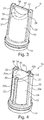
- an inventive filter 10 is candle-shaped with a socket-like base 14 is formed.
- the annular base 14 is provided on its outside with a sealing ring 16, so that the filter 10 can be installed with the base 14 in a line.
- the support struts 20 form with the base 14, a frame part 12, in which a cup-shaped or pocket-shaped filter element 30 is received and held. How out Fig. 2 it can be seen, the support strut 20 along the inside and the outside of the filter element 30 is arranged.
- welded marginal edges of the filter element 30 can be enclosed or enclosed on both sides by a support strut 20.
- a fluid may flow through the socket 14 into an internal cavity of the filter 10 and then through the filter element 30.
- a flow from the outside to the inside can take place.
- the filter element 30 is formed from a thin filter material 31, in particular a filter fabric.
- the filter element 30 has a sleeve-shaped peripheral region 34.
- a foot portion 32 of the filter element 30 is open and incorporated in the annular base 14.
- the filter element 30 is closed.
- the filter element 30 with the peripheral region 34 and the head region 36 is formed from a single piece of filter material 31 by folding and welding two longitudinal marginal edges. The welded edges are shown in the illustration Fig. 1 obscured by the beam-like support struts 20.
- the head region 36 of the filter element 30 has a saddle shape with a curved edge 42.
- two lateral tips 38 are formed on two opposite convex portions.
- two troughs 39 are arranged in an adjacent concave area of the edge 42.
- Between the two equal-height tips 38 extends transversely to a longitudinal axis of the filter 10 and also transversely to the connecting line between the two tips 38 a groove-shaped groove 40.
- the bottom of the groove-shaped groove 40 passes through the two low points 39, which are arranged at the same level.
- the saddle-shaped head portion 36 has the special shape of a relatively large filter surface with a high dimensional stability. Due to the high dimensional stability, it is sufficient in the embodiment shown that the thin-walled filter element 30 is held exclusively by a substantially linear connection with the inner and outer support struts 20.
- the support struts 20 each have at their upper free end a radially inwardly projecting cap 22, in each of which a tip 38 is at least partially received and held.
- the filter element 30 can be glued into the frame part 12 or preferably connected directly to the frame part 12 during injection molding.
- FIG Fig. 3 Another embodiment of a filter 10 according to the invention is shown in FIG Fig. 3 shown, wherein the filter 10 is constructed substantially as the filter 10 of Fig. 1 , In contrast to the filter 10 according to Fig. 1 shows the second embodiment Fig. 2 on the head portion 36 an additional cross member 24.
- the bar-shaped transverse strut 24 extends between the two distal ends of the two support struts 20.
- the filter material 31 of the filter element 30 is connected in the head region 36 with the corresponding contoured underside of the transverse strut 24.
- the cross member 24 serves as an additional stiffening and support of the filter surface on the head portion 36th
- the third embodiment of a filter 10 according to the invention Fig. 4 is based on the described first embodiment according to Fig. 1 ,
- the frame part 12 has a second pair of support struts 20b, wherein the two pairs are arranged offset by 90 ° to each other.
- the support struts 20a of the first pair extend in accordance with the embodiment Fig. 4
- the support struts 20b of the second pair extend from the socket 14 along the peripheral portion 34 of the filter element 30 to the troughs 39 of the groove 40 on the saddle-shaped head portion 36.
- the head portion 36 is thus supported and held at the maxima and minima of the edge region 42 by the vertical support struts 20a, 20b with their respective radially inwardly projecting cover caps 22.
- a welded edge 34 indicated at the edge 42 of the head portion 36 which further extends along the struts 20a at the peripheral portion 34 of the sleeve-shaped filter portion 30 to the base 14.
- a fourth embodiment of a filter 10 according to the invention is shown.
- the fourth embodiment largely corresponds to the third embodiment according to Fig. 4 , wherein the two pairs of support struts 20a, 20b respectively at the head portion 36 have a transverse strut 24a, 24b.
- the two transverse struts 24a, 24b intersect in the region of the longitudinal axis of the filter 10 at a right angle.
- the two transverse struts 24a, 24b are formed as relatively thin beams, which follow in their direction of extension of the saddle shape of the head portion 36 and conform to the respective contour.
- a fifth embodiment of a filter 10 according to the invention which has a frame member 12 with two support struts 20.
- This fifth embodiment is similar to the embodiment according to FIG Fig. 1 wherein in the filter 10 according to the fifth embodiment, the filter element 30 is conical.
- the filter element 30 tapers from the base 14 to the head region 36.
- the frame part 12 is formed with two transverse struts 20, which extend inclined towards the center and are adapted to the conical outer contour of the peripheral region 34 of the filter element 30.
- the embodiments according to the FIGS. 1 to 5 can also be conical, while the embodiment according to Fig. 6 can also be cylindrical.
Landscapes
- Chemical & Material Sciences (AREA)
- Chemical Kinetics & Catalysis (AREA)
- Engineering & Computer Science (AREA)
- Textile Engineering (AREA)
- Filtering Of Dispersed Particles In Gases (AREA)
- Filtering Materials (AREA)
- Filtration Of Liquid (AREA)
Claims (12)
- Filtre destiné à filtrer un liquide ou un gaz, avec- un élément filtrant (30) présentant une forme de poche, lequel présente une zone périphérique (34) en forme de douille, une zone supérieure (36) fermée et une zone inférieure (32) ouverte, et- un élément de cadre (12), qui présente un socle (14) annulaire de type tubulure, dans lequel la zone inférieure (32) de l'élément filtrant (30) est logée, et au moins une entretoise d'appui (20), qui s'étend en s'éloignant du socle (14) le long de la zone périphérique (34) de l'élément filtrant (30),caractérisé en ce
que la zone supérieure (36), opposée au socle (14), de l'élément filtrant (30) est réalisée en forme de selle, dans lequel deux pointes (38) latérales sont prévues, entre lesquelles une gorge (40) présentant une forme de rigole est réalisée. - Filtre selon la revendication 1,
caractérisé en ce
que l'élément filtrant (30) présentant une forme de poche est formé à partir d'un unique matériau filtrant (31) plat par pliage et soudage d'arêtes de bordure (33). - Filtre selon la revendication 2,
caractérisé en ce
que deux arêtes de bordure (33) soudées sont prévues, lesquelles s'étendent le long d'un axe longitudinal de l'élément filtrant (30) et s'étendent depuis la zone inférieure (32) en direction de la zone supérieure (36) de l'élément filtrant (30) présentant une forme de poche. - Filtre selon l'une quelconque des revendications 1 à 3,
caractérisé en ce
que l'au moins une entretoise de soutien (20) s'étend le long au moins d'une arête de bordure (33) soudée de l'élément filtrant (30) depuis le socle (14) jusqu'à l'une des pointes (38) dans la zone supérieure (36), et
en ce que l'arête de bordure (33) soudée est recouverte par l'entretoise de soutien (20). - Filtre selon l'une quelconque des revendications 1 à 4,
caractérisé en ce
qu'au moins deux entretoises de soutien (20) sont prévues par paire, lesquelles s'étendent le long de côtés se faisant face de l'élément filtrant (30) présentant une forme de poche. - Filtre selon la revendication 5,
caractérisé en ce
que les deux entretoises de soutien (20) d'une paire sont reliées l'une à l'autre par au moins une entretoise transversale (24) au niveau de la zone supérieure (36). - Filtre selon la revendication 5 ou 6,
caractérisé en ce
que deux paires d'entretoises de soutien (20) sont disposées, lesquelles sont disposées selon un décalage de 90° l'une par rapport à l'autre au niveau de la périphérie du socle (14). - Filtre selon la revendication 6 ou 7,
caractérisé en ce
que l'au moins une entretoise transversale (24) est adaptée à la forme de selle de la zone supérieure (36). - Filtre selon l'une quelconque des revendications 1 à 8,
caractérisé en ce
qu'au moins une entretoise de soutien (20) et/ou au moins une entretoise transversale (24) sont disposées au niveau du côté intérieur et du côté extérieur de l'élément filtrant (30) présentant une forme de poche et sont reliées à ce dernier. - Filtre selon l'une quelconque des revendications 1 à 9,
caractérisé en ce
que l'élément de cadre (12) est fabriqué à partir d'un matériau en plastique par coulée, en particulier par moulage par injection, dans lequel l'élément filtrant (30) est relié de manière solidaire à l'élément de cadre (12) lors de la coulée. - Filtre selon l'une quelconque des revendications 1 à 10,
caractérisé en ce
que l'élément filtrant (30) présente un tissu, un non-tissé, un tricot et/ou une membrane. - Filtre selon l'une quelconque des revendications 1 à 11,
caractérisé en ce
que la zone périphérique (34) de l'élément filtrant (30) est réalisée de manière cylindrique ou de manière conique.
Priority Applications (7)
| Application Number | Priority Date | Filing Date | Title |
|---|---|---|---|
| ES15152464.2T ES2632793T3 (es) | 2015-01-26 | 2015-01-26 | Filtro para filtrar un líquido o un gas |
| PL15152464T PL3047890T3 (pl) | 2015-01-26 | 2015-01-26 | Filtr do filtrowania cieczy lub gazu |
| EP15152464.2A EP3047890B1 (fr) | 2015-01-26 | 2015-01-26 | Filtre destiné à filtrer un liquide ou un gaz |
| JP2017539337A JP2018508347A (ja) | 2015-01-26 | 2015-10-29 | 液体または気体を濾過するためのフィルタ |
| US15/535,209 US10315145B2 (en) | 2015-01-26 | 2015-10-29 | Filter for filtering a liquid or a gas |
| CN201580074626.XA CN107206296B (zh) | 2015-01-26 | 2015-10-29 | 用于过滤液体或气体的过滤器 |
| PCT/EP2015/075093 WO2016119926A1 (fr) | 2015-01-26 | 2015-10-29 | Filtre de filtration d'un liquide ou d'un gaz |
Applications Claiming Priority (1)
| Application Number | Priority Date | Filing Date | Title |
|---|---|---|---|
| EP15152464.2A EP3047890B1 (fr) | 2015-01-26 | 2015-01-26 | Filtre destiné à filtrer un liquide ou un gaz |
Publications (2)
| Publication Number | Publication Date |
|---|---|
| EP3047890A1 EP3047890A1 (fr) | 2016-07-27 |
| EP3047890B1 true EP3047890B1 (fr) | 2017-04-19 |
Family
ID=52391876
Family Applications (1)
| Application Number | Title | Priority Date | Filing Date |
|---|---|---|---|
| EP15152464.2A Active EP3047890B1 (fr) | 2015-01-26 | 2015-01-26 | Filtre destiné à filtrer un liquide ou un gaz |
Country Status (7)
| Country | Link |
|---|---|
| US (1) | US10315145B2 (fr) |
| EP (1) | EP3047890B1 (fr) |
| JP (1) | JP2018508347A (fr) |
| CN (1) | CN107206296B (fr) |
| ES (1) | ES2632793T3 (fr) |
| PL (1) | PL3047890T3 (fr) |
| WO (1) | WO2016119926A1 (fr) |
Families Citing this family (3)
| Publication number | Priority date | Publication date | Assignee | Title |
|---|---|---|---|---|
| CN109821306A (zh) * | 2019-03-20 | 2019-05-31 | 镇江东亚碳素焦化有限公司 | 一种煅烧焦炭的除尘装置及其除尘方法 |
| CN115069029B (zh) * | 2022-06-27 | 2025-05-13 | 无锡亿利环保科技有限公司 | 滤纸筒结构、圆筒形空气滤芯及滤芯制作工艺 |
| EP4647140A1 (fr) * | 2024-05-08 | 2025-11-12 | MANN+HUMMEL GmbH | Système de filtration pour filtrer des fluides et élément filtrant pour un système de filtration |
Family Cites Families (9)
| Publication number | Priority date | Publication date | Assignee | Title |
|---|---|---|---|---|
| JPS5160512U (fr) * | 1974-11-08 | 1976-05-13 | ||
| DE8526820U1 (de) * | 1985-09-19 | 1989-01-12 | Gebrüder Holder GmbH & Co, 7430 Metzingen | Pflanzenschutzmittel-Tank |
| DE19946551A1 (de) | 1999-09-29 | 2001-04-05 | Mannesmann Vdo Ag | Zur Montage strömungsseitig vor einer Pumpe einer Scheibenreinigungsanlage eines Kraftfahrzeuges vorgesehener Filter |
| JP2001120920A (ja) | 1999-10-21 | 2001-05-08 | Gp Daikyo Corp | オイルストレーナ |
| ATE454071T1 (de) * | 2001-07-30 | 2010-01-15 | Ohki Co Ltd | Filterbeutel |
| DE202008012284U1 (de) | 2008-09-15 | 2008-12-24 | Karl Küfner KG | Filter für flüssige und gasförmige Medien |
| US20110132817A1 (en) * | 2009-12-03 | 2011-06-09 | Eric Rankin Gardner | Systems and methods associated with straining a pipeline |
| JP2011148312A (ja) * | 2011-02-09 | 2011-08-04 | Nifco Inc | メッシュ、そのメッシュを用いたフィルタとそのフィルタの製造方法 |
| DE202011109523U1 (de) | 2011-12-21 | 2013-03-25 | Reutter Gmbh | Filter zum Einsetzen in einen Einfüllstutzen eines Behälters |
-
2015
- 2015-01-26 PL PL15152464T patent/PL3047890T3/pl unknown
- 2015-01-26 EP EP15152464.2A patent/EP3047890B1/fr active Active
- 2015-01-26 ES ES15152464.2T patent/ES2632793T3/es active Active
- 2015-10-29 JP JP2017539337A patent/JP2018508347A/ja not_active Ceased
- 2015-10-29 US US15/535,209 patent/US10315145B2/en not_active Expired - Fee Related
- 2015-10-29 CN CN201580074626.XA patent/CN107206296B/zh active Active
- 2015-10-29 WO PCT/EP2015/075093 patent/WO2016119926A1/fr not_active Ceased
Non-Patent Citations (1)
| Title |
|---|
| None * |
Also Published As
| Publication number | Publication date |
|---|---|
| CN107206296B (zh) | 2019-12-24 |
| ES2632793T3 (es) | 2017-09-15 |
| JP2018508347A (ja) | 2018-03-29 |
| PL3047890T3 (pl) | 2017-08-31 |
| EP3047890A1 (fr) | 2016-07-27 |
| WO2016119926A1 (fr) | 2016-08-04 |
| CN107206296A (zh) | 2017-09-26 |
| US20170354909A1 (en) | 2017-12-14 |
| US10315145B2 (en) | 2019-06-11 |
Similar Documents
| Publication | Publication Date | Title |
|---|---|---|
| EP3525913B1 (fr) | Élément filtrant rond, en particulier pour la filtration de gaz | |
| DE102014016908B4 (de) | Filterelement mit Filterbalg, Filtersystem und Verwendung des Filtersystems | |
| EP3452205B1 (fr) | Élément filtrant, en particulier pour la filtration de gaz, et dispositif de filtration | |
| EP2481460B2 (fr) | Elément de filtration d'un filtre à liquide et filtre à liquide | |
| EP2676713B1 (fr) | Insert de filtre à gaz | |
| DE102014009887A1 (de) | Filterelement, Filter mit einem Filterelement und Filtergehäuse eines Filters | |
| WO2013045285A1 (fr) | Elément filtrant | |
| DE102014007373B4 (de) | Faltenförmiges Filterelement | |
| EP2845636B1 (fr) | Élément de filtre et procédé de fabrication d'un élément de filtre | |
| WO2015055584A1 (fr) | Élément filtrant, en particulier pour la filtration de gaz | |
| WO2016119926A1 (fr) | Filtre de filtration d'un liquide ou d'un gaz | |
| EP2125157B1 (fr) | Filtre pour fluide avec un élément filtrant pouvant être inséré dans un boîtier de filtre | |
| DE102014010260A1 (de) | Luftfiltervorrichtung,insbesondere für ein Kraftfahrzeug | |
| DE202011002684U1 (de) | Filter zum Einsetzen in den Einfüllstutzen eines Behälters | |
| DE102008008328B4 (de) | Luftfiltereinsatz mit Verstärkungsring | |
| EP4098346B1 (fr) | Dispositif filtre | |
| EP3297745B1 (fr) | Élément filtrant, en particulier pour la filtration de gaz | |
| DE102009048588A1 (de) | Filtereinrichtung, insbesondere zur Flüssigkeitsfilterung in Brennkraftmaschinen | |
| EP3452201B1 (fr) | Dispositif de filtration, en particulier filtre à gaz | |
| DE20102217U1 (de) | Filter für Flüssigkeiten, insbesondere Kraftstoffe | |
| DE102012012349B4 (de) | Gas-Filtereinsatz, Verfahren zu dessen Herstellung und Luftfilter für eine Brennkraftmaschine | |
| WO2017190871A1 (fr) | Élément filtrant annulaire, en particulier pour la filtration de gaz, et dispositif de filtration | |
| DE10216349C1 (de) | Gehäuse für eine Airbageinrichtung mit Gehäuseversteifungen | |
| DE102013004284A1 (de) | Filtereinrichtung und Filterelement für eine Filtereinrichtung | |
| EP4426468B1 (fr) | Élément filtrant rond servant à filtrer un fluide gazeux |
Legal Events
| Date | Code | Title | Description |
|---|---|---|---|
| PUAI | Public reference made under article 153(3) epc to a published international application that has entered the european phase |
Free format text: ORIGINAL CODE: 0009012 |
|
| 17P | Request for examination filed |
Effective date: 20150923 |
|
| AK | Designated contracting states |
Kind code of ref document: A1 Designated state(s): AL AT BE BG CH CY CZ DE DK EE ES FI FR GB GR HR HU IE IS IT LI LT LU LV MC MK MT NL NO PL PT RO RS SE SI SK SM TR |
|
| AX | Request for extension of the european patent |
Extension state: BA ME |
|
| GRAP | Despatch of communication of intention to grant a patent |
Free format text: ORIGINAL CODE: EPIDOSNIGR1 |
|
| INTG | Intention to grant announced |
Effective date: 20170104 |
|
| GRAS | Grant fee paid |
Free format text: ORIGINAL CODE: EPIDOSNIGR3 |
|
| GRAA | (expected) grant |
Free format text: ORIGINAL CODE: 0009210 |
|
| AK | Designated contracting states |
Kind code of ref document: B1 Designated state(s): AL AT BE BG CH CY CZ DE DK EE ES FI FR GB GR HR HU IE IS IT LI LT LU LV MC MK MT NL NO PL PT RO RS SE SI SK SM TR |
|
| REG | Reference to a national code |
Ref country code: GB Ref legal event code: FG4D Free format text: NOT ENGLISH |
|
| REG | Reference to a national code |
Ref country code: CH Ref legal event code: EP |
|
| REG | Reference to a national code |
Ref country code: AT Ref legal event code: REF Ref document number: 885397 Country of ref document: AT Kind code of ref document: T Effective date: 20170515 Ref country code: CH Ref legal event code: NV Representative=s name: SCHMAUDER AND PARTNER AG PATENT- UND MARKENANW, CH |
|
| REG | Reference to a national code |
Ref country code: IE Ref legal event code: FG4D Free format text: LANGUAGE OF EP DOCUMENT: GERMAN |
|
| REG | Reference to a national code |
Ref country code: DE Ref legal event code: R096 Ref document number: 502015000874 Country of ref document: DE |
|
| REG | Reference to a national code |
Ref country code: NL Ref legal event code: MP Effective date: 20170419 |
|
| REG | Reference to a national code |
Ref country code: LT Ref legal event code: MG4D |
|
| REG | Reference to a national code |
Ref country code: ES Ref legal event code: FG2A Ref document number: 2632793 Country of ref document: ES Kind code of ref document: T3 Effective date: 20170915 |
|
| PG25 | Lapsed in a contracting state [announced via postgrant information from national office to epo] |
Ref country code: NL Free format text: LAPSE BECAUSE OF FAILURE TO SUBMIT A TRANSLATION OF THE DESCRIPTION OR TO PAY THE FEE WITHIN THE PRESCRIBED TIME-LIMIT Effective date: 20170419 |
|
| PG25 | Lapsed in a contracting state [announced via postgrant information from national office to epo] |
Ref country code: HR Free format text: LAPSE BECAUSE OF FAILURE TO SUBMIT A TRANSLATION OF THE DESCRIPTION OR TO PAY THE FEE WITHIN THE PRESCRIBED TIME-LIMIT Effective date: 20170419 Ref country code: FI Free format text: LAPSE BECAUSE OF FAILURE TO SUBMIT A TRANSLATION OF THE DESCRIPTION OR TO PAY THE FEE WITHIN THE PRESCRIBED TIME-LIMIT Effective date: 20170419 Ref country code: LT Free format text: LAPSE BECAUSE OF FAILURE TO SUBMIT A TRANSLATION OF THE DESCRIPTION OR TO PAY THE FEE WITHIN THE PRESCRIBED TIME-LIMIT Effective date: 20170419 Ref country code: NO Free format text: LAPSE BECAUSE OF FAILURE TO SUBMIT A TRANSLATION OF THE DESCRIPTION OR TO PAY THE FEE WITHIN THE PRESCRIBED TIME-LIMIT Effective date: 20170719 Ref country code: GR Free format text: LAPSE BECAUSE OF FAILURE TO SUBMIT A TRANSLATION OF THE DESCRIPTION OR TO PAY THE FEE WITHIN THE PRESCRIBED TIME-LIMIT Effective date: 20170720 |
|
| PG25 | Lapsed in a contracting state [announced via postgrant information from national office to epo] |
Ref country code: BG Free format text: LAPSE BECAUSE OF FAILURE TO SUBMIT A TRANSLATION OF THE DESCRIPTION OR TO PAY THE FEE WITHIN THE PRESCRIBED TIME-LIMIT Effective date: 20170719 Ref country code: RS Free format text: LAPSE BECAUSE OF FAILURE TO SUBMIT A TRANSLATION OF THE DESCRIPTION OR TO PAY THE FEE WITHIN THE PRESCRIBED TIME-LIMIT Effective date: 20170419 Ref country code: IS Free format text: LAPSE BECAUSE OF FAILURE TO SUBMIT A TRANSLATION OF THE DESCRIPTION OR TO PAY THE FEE WITHIN THE PRESCRIBED TIME-LIMIT Effective date: 20170819 Ref country code: SE Free format text: LAPSE BECAUSE OF FAILURE TO SUBMIT A TRANSLATION OF THE DESCRIPTION OR TO PAY THE FEE WITHIN THE PRESCRIBED TIME-LIMIT Effective date: 20170419 Ref country code: LV Free format text: LAPSE BECAUSE OF FAILURE TO SUBMIT A TRANSLATION OF THE DESCRIPTION OR TO PAY THE FEE WITHIN THE PRESCRIBED TIME-LIMIT Effective date: 20170419 |
|
| REG | Reference to a national code |
Ref country code: DE Ref legal event code: R097 Ref document number: 502015000874 Country of ref document: DE |
|
| REG | Reference to a national code |
Ref country code: FR Ref legal event code: PLFP Year of fee payment: 4 |
|
| PG25 | Lapsed in a contracting state [announced via postgrant information from national office to epo] |
Ref country code: RO Free format text: LAPSE BECAUSE OF FAILURE TO SUBMIT A TRANSLATION OF THE DESCRIPTION OR TO PAY THE FEE WITHIN THE PRESCRIBED TIME-LIMIT Effective date: 20170419 Ref country code: EE Free format text: LAPSE BECAUSE OF FAILURE TO SUBMIT A TRANSLATION OF THE DESCRIPTION OR TO PAY THE FEE WITHIN THE PRESCRIBED TIME-LIMIT Effective date: 20170419 Ref country code: DK Free format text: LAPSE BECAUSE OF FAILURE TO SUBMIT A TRANSLATION OF THE DESCRIPTION OR TO PAY THE FEE WITHIN THE PRESCRIBED TIME-LIMIT Effective date: 20170419 |
|
| PLBE | No opposition filed within time limit |
Free format text: ORIGINAL CODE: 0009261 |
|
| STAA | Information on the status of an ep patent application or granted ep patent |
Free format text: STATUS: NO OPPOSITION FILED WITHIN TIME LIMIT |
|
| PG25 | Lapsed in a contracting state [announced via postgrant information from national office to epo] |
Ref country code: SM Free format text: LAPSE BECAUSE OF FAILURE TO SUBMIT A TRANSLATION OF THE DESCRIPTION OR TO PAY THE FEE WITHIN THE PRESCRIBED TIME-LIMIT Effective date: 20170419 |
|
| REG | Reference to a national code |
Ref country code: DE Ref legal event code: R082 Ref document number: 502015000874 Country of ref document: DE Representative=s name: WUNDERLICH & HEIM PATENTANWAELTE PARTNERSCHAFT, DE |
|
| 26N | No opposition filed |
Effective date: 20180122 |
|
| PG25 | Lapsed in a contracting state [announced via postgrant information from national office to epo] |
Ref country code: MT Free format text: LAPSE BECAUSE OF FAILURE TO SUBMIT A TRANSLATION OF THE DESCRIPTION OR TO PAY THE FEE WITHIN THE PRESCRIBED TIME-LIMIT Effective date: 20170419 |
|
| PG25 | Lapsed in a contracting state [announced via postgrant information from national office to epo] |
Ref country code: LU Free format text: LAPSE BECAUSE OF NON-PAYMENT OF DUE FEES Effective date: 20180126 |
|
| REG | Reference to a national code |
Ref country code: IE Ref legal event code: MM4A |
|
| REG | Reference to a national code |
Ref country code: BE Ref legal event code: MM Effective date: 20180131 |
|
| PG25 | Lapsed in a contracting state [announced via postgrant information from national office to epo] |
Ref country code: BE Free format text: LAPSE BECAUSE OF NON-PAYMENT OF DUE FEES Effective date: 20180131 |
|
| PG25 | Lapsed in a contracting state [announced via postgrant information from national office to epo] |
Ref country code: IE Free format text: LAPSE BECAUSE OF NON-PAYMENT OF DUE FEES Effective date: 20180126 |
|
| PGFP | Annual fee paid to national office [announced via postgrant information from national office to epo] |
Ref country code: RO Payment date: 20190328 Year of fee payment: 6 |
|
| PG25 | Lapsed in a contracting state [announced via postgrant information from national office to epo] |
Ref country code: MC Free format text: LAPSE BECAUSE OF FAILURE TO SUBMIT A TRANSLATION OF THE DESCRIPTION OR TO PAY THE FEE WITHIN THE PRESCRIBED TIME-LIMIT Effective date: 20170419 |
|
| PG25 | Lapsed in a contracting state [announced via postgrant information from national office to epo] |
Ref country code: TR Free format text: LAPSE BECAUSE OF FAILURE TO SUBMIT A TRANSLATION OF THE DESCRIPTION OR TO PAY THE FEE WITHIN THE PRESCRIBED TIME-LIMIT Effective date: 20170419 |
|
| PG25 | Lapsed in a contracting state [announced via postgrant information from national office to epo] |
Ref country code: PT Free format text: LAPSE BECAUSE OF FAILURE TO SUBMIT A TRANSLATION OF THE DESCRIPTION OR TO PAY THE FEE WITHIN THE PRESCRIBED TIME-LIMIT Effective date: 20170419 |
|
| PG25 | Lapsed in a contracting state [announced via postgrant information from national office to epo] |
Ref country code: MK Free format text: LAPSE BECAUSE OF NON-PAYMENT OF DUE FEES Effective date: 20170419 Ref country code: CY Free format text: LAPSE BECAUSE OF FAILURE TO SUBMIT A TRANSLATION OF THE DESCRIPTION OR TO PAY THE FEE WITHIN THE PRESCRIBED TIME-LIMIT Effective date: 20170419 Ref country code: HU Free format text: LAPSE BECAUSE OF FAILURE TO SUBMIT A TRANSLATION OF THE DESCRIPTION OR TO PAY THE FEE WITHIN THE PRESCRIBED TIME-LIMIT; INVALID AB INITIO Effective date: 20150126 |
|
| PG25 | Lapsed in a contracting state [announced via postgrant information from national office to epo] |
Ref country code: AL Free format text: LAPSE BECAUSE OF FAILURE TO SUBMIT A TRANSLATION OF THE DESCRIPTION OR TO PAY THE FEE WITHIN THE PRESCRIBED TIME-LIMIT Effective date: 20170419 |
|
| REG | Reference to a national code |
Ref country code: CH Ref legal event code: PL |
|
| PG25 | Lapsed in a contracting state [announced via postgrant information from national office to epo] |
Ref country code: SI Free format text: LAPSE BECAUSE OF NON-PAYMENT OF DUE FEES Effective date: 20180126 Ref country code: LI Free format text: LAPSE BECAUSE OF NON-PAYMENT OF DUE FEES Effective date: 20200131 Ref country code: CH Free format text: LAPSE BECAUSE OF NON-PAYMENT OF DUE FEES Effective date: 20200131 |
|
| REG | Reference to a national code |
Ref country code: AT Ref legal event code: MM01 Ref document number: 885397 Country of ref document: AT Kind code of ref document: T Effective date: 20200126 |
|
| PG25 | Lapsed in a contracting state [announced via postgrant information from national office to epo] |
Ref country code: AT Free format text: LAPSE BECAUSE OF NON-PAYMENT OF DUE FEES Effective date: 20200126 |
|
| P01 | Opt-out of the competence of the unified patent court (upc) registered |
Effective date: 20230505 |
|
| PGFP | Annual fee paid to national office [announced via postgrant information from national office to epo] |
Ref country code: DE Payment date: 20250122 Year of fee payment: 11 |
|
| PGFP | Annual fee paid to national office [announced via postgrant information from national office to epo] |
Ref country code: ES Payment date: 20250214 Year of fee payment: 11 |
|
| PGFP | Annual fee paid to national office [announced via postgrant information from national office to epo] |
Ref country code: FR Payment date: 20250123 Year of fee payment: 11 Ref country code: CZ Payment date: 20250110 Year of fee payment: 11 Ref country code: PL Payment date: 20250114 Year of fee payment: 11 |
|
| PGFP | Annual fee paid to national office [announced via postgrant information from national office to epo] |
Ref country code: IT Payment date: 20250131 Year of fee payment: 11 Ref country code: SK Payment date: 20250116 Year of fee payment: 11 Ref country code: GB Payment date: 20250123 Year of fee payment: 11 |