EP3047974A2 - Unité de tête et appareil d'enregistrement - Google Patents
Unité de tête et appareil d'enregistrement Download PDFInfo
- Publication number
- EP3047974A2 EP3047974A2 EP16152795.7A EP16152795A EP3047974A2 EP 3047974 A2 EP3047974 A2 EP 3047974A2 EP 16152795 A EP16152795 A EP 16152795A EP 3047974 A2 EP3047974 A2 EP 3047974A2
- Authority
- EP
- European Patent Office
- Prior art keywords
- recording
- head unit
- head
- recording medium
- transporting
- Prior art date
- Legal status (The legal status is an assumption and is not a legal conclusion. Google has not performed a legal analysis and makes no representation as to the accuracy of the status listed.)
- Withdrawn
Links
- 239000007788 liquid Substances 0.000 claims abstract description 12
- 230000032258 transport Effects 0.000 claims description 16
- 238000011144 upstream manufacturing Methods 0.000 claims description 8
- 239000003595 mist Substances 0.000 description 34
- 230000007246 mechanism Effects 0.000 description 19
- 239000000853 adhesive Substances 0.000 description 13
- 230000001070 adhesive effect Effects 0.000 description 13
- 238000004804 winding Methods 0.000 description 10
- 238000007599 discharging Methods 0.000 description 9
- 238000004140 cleaning Methods 0.000 description 6
- 230000004048 modification Effects 0.000 description 3
- 238000012986 modification Methods 0.000 description 3
- 230000001105 regulatory effect Effects 0.000 description 3
- 230000006866 deterioration Effects 0.000 description 2
- 238000010586 diagram Methods 0.000 description 2
- 230000008901 benefit Effects 0.000 description 1
- 239000003599 detergent Substances 0.000 description 1
- 230000000694 effects Effects 0.000 description 1
Images


Classifications
-
- B—PERFORMING OPERATIONS; TRANSPORTING
- B41—PRINTING; LINING MACHINES; TYPEWRITERS; STAMPS
- B41J—TYPEWRITERS; SELECTIVE PRINTING MECHANISMS, i.e. MECHANISMS PRINTING OTHERWISE THAN FROM A FORME; CORRECTION OF TYPOGRAPHICAL ERRORS
- B41J2/00—Typewriters or selective printing mechanisms characterised by the printing or marking process for which they are designed
- B41J2/005—Typewriters or selective printing mechanisms characterised by the printing or marking process for which they are designed characterised by bringing liquid or particles selectively into contact with a printing material
- B41J2/01—Ink jet
- B41J2/135—Nozzles
- B41J2/145—Arrangement thereof
- B41J2/15—Arrangement thereof for serial printing
-
- B—PERFORMING OPERATIONS; TRANSPORTING
- B41—PRINTING; LINING MACHINES; TYPEWRITERS; STAMPS
- B41J—TYPEWRITERS; SELECTIVE PRINTING MECHANISMS, i.e. MECHANISMS PRINTING OTHERWISE THAN FROM A FORME; CORRECTION OF TYPOGRAPHICAL ERRORS
- B41J2/00—Typewriters or selective printing mechanisms characterised by the printing or marking process for which they are designed
- B41J2/005—Typewriters or selective printing mechanisms characterised by the printing or marking process for which they are designed characterised by bringing liquid or particles selectively into contact with a printing material
- B41J2/01—Ink jet
- B41J2/135—Nozzles
- B41J2/14—Structure thereof only for on-demand ink jet heads
- B41J2/1433—Structure of nozzle plates
-
- B—PERFORMING OPERATIONS; TRANSPORTING
- B41—PRINTING; LINING MACHINES; TYPEWRITERS; STAMPS
- B41J—TYPEWRITERS; SELECTIVE PRINTING MECHANISMS, i.e. MECHANISMS PRINTING OTHERWISE THAN FROM A FORME; CORRECTION OF TYPOGRAPHICAL ERRORS
- B41J2202/00—Embodiments of or processes related to ink-jet or thermal heads
- B41J2202/01—Embodiments of or processes related to ink-jet heads
- B41J2202/11—Embodiments of or processes related to ink-jet heads characterised by specific geometrical characteristics
-
- B—PERFORMING OPERATIONS; TRANSPORTING
- B41—PRINTING; LINING MACHINES; TYPEWRITERS; STAMPS
- B41J—TYPEWRITERS; SELECTIVE PRINTING MECHANISMS, i.e. MECHANISMS PRINTING OTHERWISE THAN FROM A FORME; CORRECTION OF TYPOGRAPHICAL ERRORS
- B41J2202/00—Embodiments of or processes related to ink-jet or thermal heads
- B41J2202/01—Embodiments of or processes related to ink-jet heads
- B41J2202/19—Assembling head units
-
- B—PERFORMING OPERATIONS; TRANSPORTING
- B41—PRINTING; LINING MACHINES; TYPEWRITERS; STAMPS
- B41J—TYPEWRITERS; SELECTIVE PRINTING MECHANISMS, i.e. MECHANISMS PRINTING OTHERWISE THAN FROM A FORME; CORRECTION OF TYPOGRAPHICAL ERRORS
- B41J2202/00—Embodiments of or processes related to ink-jet or thermal heads
- B41J2202/01—Embodiments of or processes related to ink-jet heads
- B41J2202/20—Modules
Definitions
- the present invention relates to a head unit and a recording apparatus.
- a recording apparatus which is provided with a recording head that performs recording by discharging liquid, such as ink, to a recording medium is used.
- a recording apparatus there is a case where mist which is generated as the liquid is discharged from the recording head becomes adhered to a head unit.
- a recording apparatus aiming at preventing the mist from becoming adhered is disclosed.
- JP-A-2008-93849 a recording apparatus which is provided with an ink mist capturing member having an ink passing port in a carriage, and of which an object is preventing the mist from becoming adhered by an airflow as the carriage that functions as a head unit moves, is disclosed.
- the recording apparatus of JP-A-2008-93849 captures all of the generated mist by the ink mist capturing member before the mist passes through the ink passing port.
- the mist which passes through the ink passing port becomes adhered to the head unit.
- An advantage of some aspects of the invention is to prevent mist which is generated as liquid is discharged from a recording head from becoming adhered to a head unit.
- a head unit including: a recording head which discharges liquid from nozzles; a plate portion to which the recording head is attached in a state where a nozzle forming surface on which the nozzles are formed protrudes; and a protection portion which protects the nozzle forming surface, in which the protection portion is attached to the plate portion in a state where a space is provided between the protection portion and the plate portion when viewed from an intersecting direction which intersects with a protruding direction of the nozzle forming surface, and in which the nozzle forming surface is positioned within a range of a thickness in the protruding direction of the protection portion when viewed from the intersecting direction.
- the nozzle forming surface may be positioned in a state of being recessed with respect to a protection surface on a side opposite to the plate portion of the protection portion.
- the plate portion may have a plurality of recording heads attached thereto while at least a part of the recording heads is provided at an interval.
- a recording apparatus including: the head unit.
- a moving portion which relatively moves the head unit and a recording medium may be provided, and the protection portion may be provided further on an upstream side than the recording head in a relative moving direction of at least the head unit and the recording medium.
- a transporting portion which intermittently transports the recording medium may be provided, and the moving portion may move the head unit in a direction which intersects with a transporting direction of the recording medium when the intermittent transporting is stopped.
- the moving portion may be the transporting portion which transports the recording medium with respect to the head unit
- the recording head may be a line head in which the nozzles are aligned in the direction which intersects with the transporting direction of the recording medium.
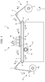
- Fig. 1 is a schematic side view of the recording apparatus 1 of the example.
- the recording apparatus 1 of the example is provided with a feeding portion 2 which can feed a roll R1 of a recording medium P for performing the recording.
- a transporting mechanism 3 which functions as a transporting portion which transports the recording medium P in a transporting direction A by an adhesive belt 10 that supports the recording medium P on a supporting surface F to which an adhesive is adhered, is provided.
- a recording mechanism 4 which performs the recording by making a recording head 7 reciprocally scan in a reciprocating direction B that intersects with the transporting direction A of the recording medium P, is provided.
- a cleaning mechanism 15 of the adhesive belt 10 is provided.
- a winding axis 17 which winds the recording medium P, and a winding mechanism 18 having a cutter 16 that cuts out the wound recording medium P are provided.
- the feeding portion 2 is provided with a rotation axis 5 that serves as a set position of the roll R1 of the recording medium P for performing the recording, and is configured to be capable of feeding the recording medium P to the transporting mechanism 3 via a driven roller 6 from the roll R1 set in the rotation axis 5.
- the rotation axis 5 rotates in a rotating direction C.
- the transporting mechanism 3 includes the adhesive belt 10 which places and transports the recording medium P fed out of the feeding portion 2, a transporting roller 8 which functions as a driving roller that moves the adhesive belt 10, and a driven roller 9.
- the recording medium P is pressed to the supporting surface F of the adhesive belt 10 by a pressing roller 12, pasted, and placed.
- the transporting roller 8 rotates in the rotating direction C, and the adhesive belt 10 moves in a direction E.
- the transporting belt is not limited to the adhesive belt.
- an electrostatic attraction type transporting belt may be used.
- the recording mechanism 4 includes the recording head 7 which can discharge ink (liquid) from nozzles N (refer to Fig. 4 ), and a carriage motor 30 (refer to Fig. 2 ) which functions as a moving portion that makes a carriage 19 which functions as a head unit, on which the recording head 7 is loaded, reciprocate in the reciprocating direction B with respect to the recording medium P.
- the reciprocating direction B in Fig. 1 is a direction which is perpendicular to a paper surface.
- the recording is performed by making the recording head 7 reciprocally scan, but in the middle of recording and scanning (when the recording head 7 is moving), the transporting mechanism 3 stops the transporting of the recording medium P.
- the reciprocating scanning of the recording head 7 and the transporting of the recording medium P are alternately performed.
- the transporting mechanism 3 intermittently transports (intermittently moves the adhesive belt 10) the recording medium P.
- the cleaning mechanism 15 of the adhesive belt 10 includes a cleaning brush 13 in which a plurality of cleaning rollers are linked in a direction of a rotation axis, and a tray 14 in which detergent for cleaning the cleaning brush 13 is input.
- the winding mechanism 18 is a mechanism which performs the recording and winds the recording medium P transported from the transporting mechanism 3 via a driven roller 11, and can perform the winding as a roll R2 of the recording medium P by setting a winding paper pipe or the like in the winding axis 17 and winding the recording medium P around this.
- the recording apparatus 1 of the example is a recording apparatus which supports the rolled recording medium P by the adhesive belt 10 and transports the recording medium P, but the recording apparatus 1 is not limited to the recording apparatus having such a configuration.
- the recording apparatus may be configured to be capable of nipping and transporting a cut-out type recording medium P other than the rolled recording medium P, by a pair or rollers which functions as a transporting portion.
- Fig. 2 is a block diagram of the recording apparatus 1 of the example.
- a CPU 24 which controls the entire recording apparatus 1 is provided.
- the CPU 24 is connected to a ROM 26 in which various control programs or the like that execute the CPU 24 are accommodated, and a RAM 27 which can temporarily accommodate data, via a system bus 25.
- the CPU 24 is connected to a head driving portion 28 for driving the recording head 7 via the system bus 25.
- the CPU 24 is connected to a motor driving portion 29 for driving the carriage motor 30, a transporting motor 31, a feeding motor 32, and a winding motor 33, via the system bus 25.
- the carriage motor 30 is a motor for moving the carriage 19 on which the recording head 7 is loaded.
- the transporting motor 31 is a motor for driving the transporting roller 8.
- the feeding motor 32 is a rotating mechanism of the rotation axis 5, and is a motor which drives the rotation axis 5 for sending out the recording medium P to the transporting mechanism 3.
- the winding motor 33 is a driving motor for rotating the winding axis 17.
- the CPU 24 is connected to a cutter driving portion 36 which drives the cutter 16 to cut out the recording medium P, via the system bus 25.
- the CPU 24 is connected to an input/output portion 37 via the system bus 25, and the input/output portion 37 is connected to a PC 38 which inputs recording data or the like from an external device.
- Fig. 3 is a schematic perspective view illustrating the carriage 19 of the example.
- Fig. 4 is a schematic bottom view illustrating the carriage 19 of the example.
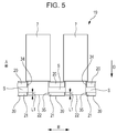
- Fig. 5 is a schematic front view illustrating the carriage 19 of the example.
- the carriage 19 of the example is provided with the recording head 7, a plate portion 20, and a protection portion 21.
- the plate portion 20 is configured to be capable of attaching the recording head 7 thereto in a state where a nozzle forming surface 22 on which the nozzles N (refer to Fig. 4 ) are formed in the recording head 7 protrudes to a lower side (adhesive belt 10 side) via a hole portion 34.
- the protection portion 21 is for protecting the nozzle forming surface 22, and as illustrated in Fig. 3 , when viewed from an intersecting direction which intersects with a protruding direction (direction which is toward the adhesive belt 10) D of the nozzle forming surface 22, the protection portion 21 is attached to the plate portion 20 by an attaching portion 40 in a state where a space S is provided between the protection portion 21 and the plate portion 20.
- the nozzle forming surface 22 when viewed from the intersecting direction, is positioned within a range of a thickness L1 in the protruding direction D of the protection portion 21 in a hole portion 35 of the protection portion 21.
- the carriage 19 of the example is configured to be capable of preventing the mist from becoming adhered to the carriage 19.
- the recording apparatus 1 of the example is configured to be capable of performing the recording by preventing the mist from becoming adhered to the carriage 19.
- the nozzle forming surface 22 is positioned in a state of being recessed with respect to a protection surface 39 on a side opposite to the plate portion 20 of the protection portion 21, not matching the protection surface 39 on a tip side (a side opposite to the plate portion 20) in the protruding direction D of the protection portion 21.
- the nozzle forming surface 22 is recessed with respect to the protection surface 39.
- the carriage 19 of the example is configured to be capable of preventing the generation of a shift in the discharging direction of the ink and the deterioration of recording quality.
- a plurality (12, in the present example) of recording heads 7 are attached to the plate portion 20 of the example at an interval.
- the plurality of recording heads 7 are attached to the plate portion 20 of the example at an interval while the recording heads 7 are not in contact with each other. However, if the plurality of recording heads 7 are configured to be attached to the plate portion 20 while at least a part of the recording heads 7 attached to the plate portion 20 is provided at an interval, it is possible to release the floating mist via the part spaced at an interval.
- the recording apparatus 1 of the example is provided with the transporting mechanism 3 which intermittently transports the recording medium P in the transporting direction A, and the carriage motor 30 which is a moving portion of the carriage 19 is configured to move the carriage 19 in the reciprocating direction B that intersects with the transporting direction A of the recording medium P when the intermittent transporting is stopped.
- the recording apparatus 1 of the example is a so-called serial type recording apparatus.
- the serial type recording apparatus is configured to be capable of performing the recording by preventing the mist from becoming adhered to the carriage 19.
- a recording apparatus which is configured to include a line head in which the nozzles N are aligned in the direction that intersects with the transporting direction A of the recording medium P, may be provided according to another embodiment of the present invention to use the head unit having a configuration (configuration in which the space S is provided) in which a positional relationship between the line head, the plate portion 20, and the protection portion 21 is similar to that of the carriage 19 of the example, and to transport (relatively move) the recording medium P with respect to the head unit by the transporting mechanism which functions as the moving portion.
- the "line head” is a recording head in which a region of the nozzles N formed in the direction that intersects with the transporting direction A of the recording medium P is provided to be capable of covering the entire direction that intersects with the transporting direction A of the recording medium P, and which is used in the recording apparatus that forms the image by relatively moving the recording head or the recording medium P.
- the region of the nozzles N in the direction that intersects with the transporting direction A of the line head may be capable of covering the entire direction that intersects with the transporting direction A of all of the recording mediums P corresponding to the recording apparatus.
- an airflow generation portion such as a fan, may be provided to be capable of releasing the mist via the space S more effectively, and the airflow may be generated in the space S.
- Fig. 6 is a schematic bottom view of the carriage 19 which is a main portion of the recording apparatus 1 of Example 2 of the invention, and is a view which corresponds to Fig. 4 illustrating the carriage 19 of Example 1.
- configuration members which are common to the above-described recording apparatus 1 are illustrated by the same reference numerals, and detailed description thereof will be omitted.
- the protection portion 21 in the carriage 19 of Example 1 has a size equivalent to that of the plate portion 20 when viewed from a bottom surface.
- the carriage 19 of the present example has a configuration in which protection portions 21a and 21b are attached to an end portion of the plate portion 20 in the reciprocating direction B of the carriage 19 in a state where the space S is provided, similar to the carriage 19 of Example 1.
- the protection portion is provided further on an upstream side than the recording head 7 in the relative moving direction (reciprocating direction B) of at least the carriage 19 and the recording medium P, it is possible to generate the airflow which releases the floating mist via the space S on the upstream side in the relative moving direction as a regulating plate. Therefore, it is possible to perform the recording by effectively preventing the mist from becoming adhered to the carriage 19.
- the recording apparatus 1 of the example is configured to be capable of performing the recording by discharging the ink from the recording head 7 when moving both in the forward direction and the reverse direction of the reciprocating direction B
- the protection portions are provided in both end portions of the plate portion 20 in the reciprocating direction B of the carriage 19.
- a role as a regulating plate can be achieved if the protection portion is provided on the upstream side in one direction.
- the head unit 19 including: the recording head 7 which can discharge the liquid from nozzles N; the plate portion 20 to which the recording head 7 is attached in a state where the nozzle forming surface 22 on which the nozzles N are formed protrudes; and the protection portion 21 which protects the nozzle forming surface 22, in which the protection portion 21 is attached to the plate portion 20 in a state where the space S is provided between the protection portion 21 and the plate portion 20 when viewed from the intersecting direction which intersects with the protruding direction D of the nozzle forming surface 22, and in which the nozzle forming surface 22 is positioned within a range of the thickness L1 in the protruding direction D of the protection portion 21 when viewed from the intersecting direction.
- the protection portion 21 is attached to the plate portion 20 in a state where the space S is provided between the protection portion 21 and the plate portion 20 when viewed from the intersecting direction, and the nozzle forming surface 22 is positioned within the range of the thickness L1 in the protruding direction D of the protection portion 21 when viewed from the intersecting direction.
- the space S is provided between the protection portion 21 and the plate portion 20 when viewed from the intersecting direction
- the nozzle forming surface 22 is positioned within the range of the thickness L1 in the protruding direction D of the protection portion 21 when viewed from the intersecting direction.
- the nozzle forming surface 22 is positioned in a state of being recessed with respect to the protection surface 39 on the side opposite to the plate portion 20 of the protection portion 21.
- the nozzle forming surface 22 is positioned in a state of being recessed with respect to the protection surface 39 on the side opposite to the plate portion 20 of the protection portion 21. In other words, the nozzle forming surface 22 is recessed with respect to the protection surface 39. For this reason, even when the airflow which flows in the intersecting direction that intersects with the protruding direction D is generated between the nozzle forming surface 22 and the recording medium P, the airflow does not influence the vicinity of the nozzle forming surface 22. Therefore, at the moment when the liquid is discharged from the nozzle forming surface 22, it is possible to suppress a force in the direction which intersects with the discharging direction of the ink.
- the plate portion 21 has the plurality of recording heads 7 attached thereto while at least a part of the recording heads 7 is provided at an interval S.
- the expression "the plurality of recording heads 7 attached thereto while at least a part of the recording heads 7 is provided at an interval” means that it is sufficient if there is a part spaced at an interval S, even when the adjacent recording heads 7 are partially in contact with each other.
- the protection portion 21 has the plurality of recording heads 7 attached thereto while at least a part of the recording heads 7 is provided at the interval S. For this reason, it is possible to release the floating mist via the part spaced at the interval S. For this reason, it is possible to effectively prevent the mist from becoming adhered to the carriage 19.
- the recording apparatus 1 includes the head unit 19 according to any one of the first to the third aspects.
- the recording apparatus 1 includes the moving portion 30 which relatively moves the head unit 19 and the recording medium P, in which the protection portion 21 is provided further on the upstream side than the recording head 7 in the relative moving direction B of at least the head unit 19 and the recording medium P.
- the protection portion 21 is provided further on the upstream side than the recording head 7 in the relative moving direction B of at least the head unit 19 and the recording medium P. For this reason, the protection portion 21 functions as the regulating plate, and it is possible to generate the airflow in which the floating mist is released via the space S on the upstream side of the relative moving direction B. Therefore, it is possible to perform the recording by effectively preventing the mist from becoming adhered to the carriage 19.
- the recording apparatus 1 includes the transporting portion 3 which intermittently transports the recording medium P, in which the moving portion 30 moves the head unit 19 in the direction which intersects with the transporting direction A of the recording medium P when the intermittent transporting is stopped.
- the transporting mechanism 3 which intermittently transports the recording medium is provided, and the carriage motor 30 moves the head unit 19 in the direction which intersects with the transporting direction A of the recording medium P when the intermittent transporting is stopped.
- the recording apparatus is a so-called serial type recording type. For this reason, in the serial type recording apparatus, it is possible to perform the recording by effectively preventing the mist from becoming adhered to the head unit 19.
- the moving portion is the transporting portion which transports the recording medium P with respect to the head unit
- the recording head is a line head in which the nozzles N are aligned in the direction which intersects with the transporting direction of the recording medium P.
- the moving portion is the transporting portion which transports the recording medium P with respect to the head unit
- the recording head is a line head in which the nozzles N are aligned in the direction which intersects with the transporting direction of the recording medium P.
Landscapes
- Ink Jet (AREA)
Applications Claiming Priority (1)
| Application Number | Priority Date | Filing Date | Title |
|---|---|---|---|
| JP2015012329A JP2016137588A (ja) | 2015-01-26 | 2015-01-26 | ヘッドユニット及び記録装置 |
Publications (2)
| Publication Number | Publication Date |
|---|---|
| EP3047974A2 true EP3047974A2 (fr) | 2016-07-27 |
| EP3047974A3 EP3047974A3 (fr) | 2016-11-30 |
Family
ID=55236290
Family Applications (1)
| Application Number | Title | Priority Date | Filing Date |
|---|---|---|---|
| EP16152795.7A Withdrawn EP3047974A3 (fr) | 2015-01-26 | 2016-01-26 | Unité de tête et appareil d'enregistrement |
Country Status (4)
| Country | Link |
|---|---|
| US (1) | US20160214383A1 (fr) |
| EP (1) | EP3047974A3 (fr) |
| JP (1) | JP2016137588A (fr) |
| CN (1) | CN105818539B (fr) |
Cited By (2)
| Publication number | Priority date | Publication date | Assignee | Title |
|---|---|---|---|---|
| NL2022897B1 (en) * | 2019-02-08 | 2020-10-15 | Canon Production Printing Holding Bv | Protective cover for an inkjet print head |
| NL2033253B1 (en) * | 2022-10-07 | 2024-04-19 | Canon Kk | Process of manufacturing droplet jetting devices |
Families Citing this family (2)
| Publication number | Priority date | Publication date | Assignee | Title |
|---|---|---|---|---|
| JP6991721B2 (ja) * | 2017-03-03 | 2022-01-12 | 住友化学株式会社 | マーキング装置、欠陥検査システム及びフィルム製造方法 |
| JP7324123B2 (ja) | 2019-11-12 | 2023-08-09 | 株式会社Screenホールディングス | インクジェット印刷装置およびインクジェット印刷方法 |
Citations (3)
| Publication number | Priority date | Publication date | Assignee | Title |
|---|---|---|---|---|
| JP2003072041A (ja) * | 2001-08-31 | 2003-03-12 | Pentel Corp | 描画装置 |
| JP2008093849A (ja) | 2006-10-06 | 2008-04-24 | Canon Inc | 液滴吐出ヘッド及び液滴吐出装置 |
| US20090027451A1 (en) * | 2007-07-24 | 2009-01-29 | Brother Kogyo Kabushiki Kaisha | Liquid droplet ejecting apparatus |
Family Cites Families (12)
| Publication number | Priority date | Publication date | Assignee | Title |
|---|---|---|---|---|
| JP2000108330A (ja) * | 1998-10-08 | 2000-04-18 | Seiko Epson Corp | インクジェット記録装置 |
| JP2009262543A (ja) * | 2008-04-03 | 2009-11-12 | Seiko Epson Corp | 流体噴射ヘッド及び流体噴射装置 |
| JP5300633B2 (ja) * | 2009-07-09 | 2013-09-25 | キヤノン株式会社 | インクジェット記録装置 |
| JP2011168032A (ja) * | 2010-02-22 | 2011-09-01 | Seiko Epson Corp | 液体噴射ヘッド、液体噴射ヘッドユニット及び液体噴射装置 |
| JP5614201B2 (ja) * | 2010-09-22 | 2014-10-29 | セイコーエプソン株式会社 | 液体噴射ヘッドユニット |
| JP2012086426A (ja) * | 2010-10-19 | 2012-05-10 | Seiko Epson Corp | 液体噴射ヘッドユニット |
| US8876244B2 (en) * | 2011-09-30 | 2014-11-04 | Eastman Kodak Company | Inkjet printing system with condensation control system |
| KR101551552B1 (ko) * | 2012-01-13 | 2015-09-08 | 세이코 엡슨 가부시키가이샤 | 카트리지, 인쇄재 공급 시스템, 인쇄 장치, 액체 수용 용기, 인쇄 시스템, 및 단자 접속 구조체 |
| JP5967350B2 (ja) * | 2012-01-24 | 2016-08-10 | セイコーエプソン株式会社 | 液体噴射ヘッドモジュール及び液体噴射装置 |
| JP6123218B2 (ja) * | 2012-02-03 | 2017-05-10 | セイコーエプソン株式会社 | 液体噴射ヘッド及び液体噴射装置 |
| JP2013256011A (ja) * | 2012-06-11 | 2013-12-26 | Seiko Epson Corp | 液体噴射ヘッド及び液体噴射装置 |
| JP6098267B2 (ja) * | 2013-03-22 | 2017-03-22 | セイコーエプソン株式会社 | 液体噴射ヘッド及び液体噴射装置 |
-
2015
- 2015-01-26 JP JP2015012329A patent/JP2016137588A/ja active Pending
-
2016
- 2016-01-14 US US14/995,701 patent/US20160214383A1/en not_active Abandoned
- 2016-01-25 CN CN201610049433.5A patent/CN105818539B/zh active Active
- 2016-01-26 EP EP16152795.7A patent/EP3047974A3/fr not_active Withdrawn
Patent Citations (3)
| Publication number | Priority date | Publication date | Assignee | Title |
|---|---|---|---|---|
| JP2003072041A (ja) * | 2001-08-31 | 2003-03-12 | Pentel Corp | 描画装置 |
| JP2008093849A (ja) | 2006-10-06 | 2008-04-24 | Canon Inc | 液滴吐出ヘッド及び液滴吐出装置 |
| US20090027451A1 (en) * | 2007-07-24 | 2009-01-29 | Brother Kogyo Kabushiki Kaisha | Liquid droplet ejecting apparatus |
Cited By (2)
| Publication number | Priority date | Publication date | Assignee | Title |
|---|---|---|---|---|
| NL2022897B1 (en) * | 2019-02-08 | 2020-10-15 | Canon Production Printing Holding Bv | Protective cover for an inkjet print head |
| NL2033253B1 (en) * | 2022-10-07 | 2024-04-19 | Canon Kk | Process of manufacturing droplet jetting devices |
Also Published As
| Publication number | Publication date |
|---|---|
| CN105818539B (zh) | 2018-05-11 |
| JP2016137588A (ja) | 2016-08-04 |
| CN105818539A (zh) | 2016-08-03 |
| US20160214383A1 (en) | 2016-07-28 |
| EP3047974A3 (fr) | 2016-11-30 |
Similar Documents
| Publication | Publication Date | Title |
|---|---|---|
| US9981474B2 (en) | Liquid ejecting apparatus | |
| US8967755B2 (en) | Image forming apparatus | |
| EP3047974A2 (fr) | Unité de tête et appareil d'enregistrement | |
| US11491808B2 (en) | Printing apparatus, transport control method | |
| JP2016055540A (ja) | 画像記録装置 | |
| US9987848B2 (en) | Ink jet recording apparatus and cleaning method thereof | |
| EP2754560B1 (fr) | Appareil d'enregistrement | |
| EP2756957A1 (fr) | Appareil d'enregistrement et procédé d'enregistrement | |
| US20120127227A1 (en) | Image recording apparatus and method of controlling image recording apparatus | |
| US20160082737A1 (en) | Liquid ejecting apparatus and liquid ejecting method | |
| JP2019031047A (ja) | 印刷装置 | |
| EP3085537B1 (fr) | Appareil de décharge de liquide | |
| JP6384064B2 (ja) | 記録装置 | |
| EP3069886A1 (fr) | Appareil d'enregistrement | |
| JP2015139891A (ja) | 印刷制御装置及び印刷装置並びに印刷方法 | |
| JP6325400B2 (ja) | インクジェット印刷方法およびインクジェット印刷装置 | |
| US10071550B2 (en) | Recording apparatus for ejecting ink | |
| EP3085542A1 (fr) | Appareil d'enregistrement | |
| JP2019123184A (ja) | 媒体切断方法及び記録装置 | |
| JP2015166166A (ja) | プリント装置およびシート支持装置 | |
| JP6450962B2 (ja) | 記録装置 | |
| JP5832623B2 (ja) | インクジェット記録装置及び記録ヘッドの回復方法 | |
| JP2019209604A (ja) | 印刷装置 | |
| JP7236026B2 (ja) | 印刷装置 | |
| JP2016168759A (ja) | 記録装置 |
Legal Events
| Date | Code | Title | Description |
|---|---|---|---|
| PUAI | Public reference made under article 153(3) epc to a published international application that has entered the european phase |
Free format text: ORIGINAL CODE: 0009012 |
|
| AK | Designated contracting states |
Kind code of ref document: A2 Designated state(s): AL AT BE BG CH CY CZ DE DK EE ES FI FR GB GR HR HU IE IS IT LI LT LU LV MC MK MT NL NO PL PT RO RS SE SI SK SM TR |
|
| AX | Request for extension of the european patent |
Extension state: BA ME |
|
| PUAL | Search report despatched |
Free format text: ORIGINAL CODE: 0009013 |
|
| AK | Designated contracting states |
Kind code of ref document: A3 Designated state(s): AL AT BE BG CH CY CZ DE DK EE ES FI FR GB GR HR HU IE IS IT LI LT LU LV MC MK MT NL NO PL PT RO RS SE SI SK SM TR |
|
| AX | Request for extension of the european patent |
Extension state: BA ME |
|
| RIC1 | Information provided on ipc code assigned before grant |
Ipc: B41J 2/155 20060101AFI20161025BHEP Ipc: B41J 2/15 20060101ALI20161025BHEP |
|
| 17P | Request for examination filed |
Effective date: 20170530 |
|
| RBV | Designated contracting states (corrected) |
Designated state(s): AL AT BE BG CH CY CZ DE DK EE ES FI FR GB GR HR HU IE IS IT LI LT LU LV MC MK MT NL NO PL PT RO RS SE SI SK SM TR |
|
| 17Q | First examination report despatched |
Effective date: 20190219 |
|
| STAA | Information on the status of an ep patent application or granted ep patent |
Free format text: STATUS: THE APPLICATION HAS BEEN WITHDRAWN |
|
| 18W | Application withdrawn |
Effective date: 20190503 |