EP3047982A1 - Pneu de motocyclette pour terrains accidentés - Google Patents
Pneu de motocyclette pour terrains accidentés Download PDFInfo
- Publication number
- EP3047982A1 EP3047982A1 EP16151773.5A EP16151773A EP3047982A1 EP 3047982 A1 EP3047982 A1 EP 3047982A1 EP 16151773 A EP16151773 A EP 16151773A EP 3047982 A1 EP3047982 A1 EP 3047982A1
- Authority
- EP
- European Patent Office
- Prior art keywords
- block
- tire
- blocks
- region
- shoulder
- Prior art date
- Legal status (The legal status is an assumption and is not a legal conclusion. Google has not performed a legal analysis and makes no representation as to the accuracy of the status listed.)
- Granted
Links
Images


Classifications
-
- B—PERFORMING OPERATIONS; TRANSPORTING
- B60—VEHICLES IN GENERAL
- B60C—VEHICLE TYRES; TYRE INFLATION; TYRE CHANGING; CONNECTING VALVES TO INFLATABLE ELASTIC BODIES IN GENERAL; DEVICES OR ARRANGEMENTS RELATED TO TYRES
- B60C11/00—Tyre tread bands; Tread patterns; Anti-skid inserts
- B60C11/03—Tread patterns
- B60C11/11—Tread patterns in which the raised area of the pattern consists only of isolated elements, e.g. blocks
-
- B—PERFORMING OPERATIONS; TRANSPORTING
- B60—VEHICLES IN GENERAL
- B60C—VEHICLE TYRES; TYRE INFLATION; TYRE CHANGING; CONNECTING VALVES TO INFLATABLE ELASTIC BODIES IN GENERAL; DEVICES OR ARRANGEMENTS RELATED TO TYRES
- B60C11/00—Tyre tread bands; Tread patterns; Anti-skid inserts
- B60C11/03—Tread patterns
- B60C11/0327—Tread patterns characterised by special properties of the tread pattern
- B60C11/033—Tread patterns characterised by special properties of the tread pattern by the void or net-to-gross ratios of the patterns
-
- B—PERFORMING OPERATIONS; TRANSPORTING
- B60—VEHICLES IN GENERAL
- B60C—VEHICLE TYRES; TYRE INFLATION; TYRE CHANGING; CONNECTING VALVES TO INFLATABLE ELASTIC BODIES IN GENERAL; DEVICES OR ARRANGEMENTS RELATED TO TYRES
- B60C11/00—Tyre tread bands; Tread patterns; Anti-skid inserts
- B60C11/03—Tread patterns
- B60C11/13—Tread patterns characterised by the groove cross-section, e.g. for buttressing or preventing stone-trapping
- B60C11/1369—Tie bars for linking block elements and bridging the groove
-
- B—PERFORMING OPERATIONS; TRANSPORTING
- B60—VEHICLES IN GENERAL
- B60C—VEHICLE TYRES; TYRE INFLATION; TYRE CHANGING; CONNECTING VALVES TO INFLATABLE ELASTIC BODIES IN GENERAL; DEVICES OR ARRANGEMENTS RELATED TO TYRES
- B60C11/00—Tyre tread bands; Tread patterns; Anti-skid inserts
- B60C11/03—Tread patterns
- B60C11/13—Tread patterns characterised by the groove cross-section, e.g. for buttressing or preventing stone-trapping
- B60C11/1376—Three dimensional block surfaces departing from the enveloping tread contour
-
- B—PERFORMING OPERATIONS; TRANSPORTING
- B60—VEHICLES IN GENERAL
- B60C—VEHICLE TYRES; TYRE INFLATION; TYRE CHANGING; CONNECTING VALVES TO INFLATABLE ELASTIC BODIES IN GENERAL; DEVICES OR ARRANGEMENTS RELATED TO TYRES
- B60C2200/00—Tyres specially adapted for particular applications
- B60C2200/10—Tyres specially adapted for particular applications for motorcycles, scooters or the like
-
- B—PERFORMING OPERATIONS; TRANSPORTING
- B60—VEHICLES IN GENERAL
- B60C—VEHICLE TYRES; TYRE INFLATION; TYRE CHANGING; CONNECTING VALVES TO INFLATABLE ELASTIC BODIES IN GENERAL; DEVICES OR ARRANGEMENTS RELATED TO TYRES
- B60C2200/00—Tyres specially adapted for particular applications
- B60C2200/14—Tyres specially adapted for particular applications for off-road use
Definitions
- the present invention relates to motorcycle tires for running on rough terrain, and in particular, relates to a motorcycle tire having an improved tread block arrangement.
- motorcycle tires for running on rough terrain which is used in motocross or the like include a tread portion provided with a plurality of tread blocks. Such a tire can obtain grip or traction since tread blocks bite in the ground.
- Japanese Unexamined Patent Application Publication No. 2014-141163 discloses a motorcycle tire for running on rough terrain which includes a tread portion provided with a plurality of blocks arranged on the respective central, middle and shoulder regions. Furthermore, each land ratio of each region is defined in a certain range.
- the present invention has an object to provide a motorcycle tire for running on rough terrain having an improved tread block arrangement to offer an excellent transient characteristic of cornering.
- a motorcycle tire for running on rough terrain includes a tread portion including a central region having a development width of one third of a tread development width, a pair of shoulder regions each having a development width of one sixth of the tread development width from each tread edge, and a middle region defined between the central region and one of the shoulder regions on each side of a tire equator.
- the tread portion is provided with at least one central block having a ground contact face whose centroid is located within the central region, at least one shoulder block having a ground contact face whose centroid is located within the shoulder region on each side of the tire equator, and at least one middle block having a ground contact face whose centroid is located within the middle region on each side of the tire equator.
- the adjacent two blocks on the tire meridian cross section may be arranged so as to overlap one another at the respective ground contact faces at least partially.
- said at least one shoulder block may include an outer shoulder block forming one of the tread edges and an inner shoulder block which partially overlaps both of the outer shoulder block and the middle block on the tire meridian cross section, and an overlap amount between the inner shoulder block and the outer shoulder block may be greater than an overlap amount between the inner shoulder block and the middle block.
- the tread portion may include a triangular arrangement of blocks which includes two outer shoulder blocks arranged separately in the circumferential direction of the tire to form a circumferential gap therebetween, and the middle block arranged axially inward of the gap.
- Each outer shoulder block may have an axial width gradually decreasing toward the gap.
- Tie-bars arranged in a triangular manner to connect the triangular arrangement of blocks may be provided.
- the outer shoulder block may have the ground contact face having a circumferential length gradually decreasing axially inwardly.
- the outer shoulder block may have the ground contact face having a circumferential length gradually decreasing axially inwardly.
- said at least one shoulder block may include a dented shoulder block having an axially inner sidewall which is dented.
- a land ratio of the central region may be in a range of from 11% to 15%, each land ratio of each middle region may be 2 to 5 percentage points greater than the land ratio of the central region, and each land ratio of each shoulder region may be 8 to 11 percentage point greater than the land ratio of the central region and 5 to 7 percentage points greater than the land ratio of each middle region.
- a land ratio of the entire tread portion may be in a range of from 14% to 21%.
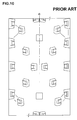
- FIG. 1 illustrates a development view of a tread portion 2 of a motorcycle tire 1 for running on rough terrain according to an embodiment of the present invention.
- the tire 1 according to the embodiment of the present invention may preferably be embodied as a tire for motocross race, for example.
- the tread portion 2 of the tire in accordance with the present embodiment is smoothly curved in an arc manner (not shown) so as to protrude radially outwardly in a tire meridian cross section including the tire axis.
- FIG. 1 illustrates a development shape of the curved tread portion 2.
- the tire 1 includes a tread pattern including a plurality of circumferentially repeated design units or block groups 7 illustrated in FIG.1 .
- the tread portion 2 includes a central region 3, a pair of middle regions 4 and a pair of shoulder regions 5.
- the respective regions 3, 4 and 5 are provided with at least one, preferably a plurality of blocks 10. Note that each ground contact face of each block 10 is illustrated in FIG. 1 .
- the tread pattern in accordance with the present embodiment is designed in substantially symmetrical block arrangements with respect to the tire equator C. However, note that the present invention is not particularly limited to this aspect.
- the central region 3 is a region having a development width of one third of a tread development width TWe with a center corresponding to the tire equator C.
- the tread development width TWe is a distance between tread edges Te and Te measured along a plane when the tread portion 2 is developed in the plane.
- Each of the tread edges Te is an axially outermost edge of a block disposed axially outermost in the blocks 10 on the tread portion 2 on each side of the tire equator C.
- Each of the shoulder regions 5 is a region having a development width of one sixth of the tread development width TWe from each tread edge Te toward the tire equator C.
- Each of the middle regions 4 is a region between the central region 3 and the shoulder region 5 on each side of the tire equator C.
- the blocks 10 include at least one central block 20, at least one middle block 30 and at least one shoulder block 40.
- the central block 20 has a ground contact face whose centroid is located within the central region 3.
- the middle block 30 has a ground contact face whose centroid is located within the middle region 4.
- the shoulder block 40 has a ground contact face whose centroid is located within the shoulder region 5.
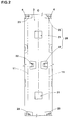
- FIG. 2 illustrates an enlarged view of the central region 3.
- the at least one central block 20 includes a first central block 21, a second central block 22 and a third central block 23.
- the respective centroids of the central blocks 20 are positioned in different places so that the centroids thereof are located axially outwardly in order from the first central block 21, the second central block 22 and the third central block 23.
- the first central block 21, for example, is arranged on the tire equator C.
- the first central block 21, for example, is arranged so that the entire of the block is within the central region 3 without crossing the first boundary 11 between the central region 3 and the middle region 4.
- the second central block 22 for example, is arranged so that its ground contact face is between the first boundary 11 and the tire equator C without crossing both of the first boundary 11 and the tire equator C.
- the second central block 22 is located in a slightly outward position in the axial direction of the tire with respect to the first central block 21.
- the second central block 22, for example is arranged so as to overlap with the first central block 21 at least partially when the first central block 21 and the second central block 22 are projected onto an arbitrary tire meridian cross section along the circumferential direction of the tire.
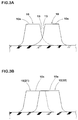
- FIGs. 3A and 3B illustrate projection views of axially adjacent blocks overlapping one another on the tire meridian cross section.
- two overlapping blocks should be understood so as to include these aspects illustrated in FIGs. 3A and 3B .
- FIG. 3A two blocks 10 are overlapped one another at least partially at the respective sidewalls 13 of the blocks. However, the respective ground contact faces 10s are not overlapped one another.
- FIG. 3B two blocks 10 are overlapped one another at least partially at the respective ground contact faces 10s.
- the first central block 21 and the second central block 22 are overlapped at the respective ground contact faces 10s on the tire meridian cross section as illustrated in FIG. 3B .
- the third central block 23 is arranged so as to cross the first boundary 11 between the central region 3 and the middle region 4. Furthermore, the third central block 23 is arranged so as to overlap with the second central block 22 at least partially when both blocks 22 and 23 are projected onto a tire meridian cross section along the circumferential direction of the tire.
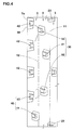
- FIG. 4 is an enlarged view of the middle region 4 and the shoulder region 5.
- the at least one middle block 30 includes a first middle block 31, a second middle block 32 and a third middle block 33.
- the respective centroids of the middle blocks 30 are positioned in different places so that the centroids thereof are located axially outwardly in order from the first middle block 31, the second middle block 32 and the third middle block 33.
- the first middle block 31 is an axially innermost block in the middle blocks 30.
- the first middle block 31, for example, is arranged proximate to the first boundary 11 between the central region 3 and the middle region 4.
- the first middle block 31 is arranged so as to overlap with the third central block 23 when the both blocks 31 and 23 are projected onto a tire meridian cross section along the circumferential direction of the tire.
- the second middle block 32 is located between the first boundary 11 and the second boundary 12 between the middle region 4 and the shoulder region 5. Furthermore, the second middle block 32 is arranged so as to overlap with the first middle block 31 at least partially when the both blocks 31 and 32 are projected onto a tire meridian cross section along the circumferential direction of the tire.
- the third middle block 33 is located so as to cross the second boundary 12. Furthermore, the third middle block 33 is arranged so as to overlap with the second middle block 32 at least partially when the both blocks 32 and 33 are projected onto a tire meridian cross section along the circumferential direction of the tire. In addition, the third middle block 33 is arranged so as to overlap with the first middle block 31 at least partially when the both blocks 31 and 33 are projected onto a tire meridian cross section.
- the at least one shoulder block 40 for example, includes an inner shoulder block 41 arranged axially inwardly in the shoulder region 5 and an outer shoulder block 42 arranged axially outwardly in the shoulder region 5. Namely, the centroid of the ground contact face of the outer shoulder block 42 is positioned axially outward of the centroid of the ground contact face of the inner shoulder block 41.
- the inner shoulder block 41 for example, is arranged so as to cross the second boundary 12. Furthermore, the inner shoulder block 41 is arranged so as to overlap with the third middle block 33 at least partially when the both blocks 41 and 33 are projected onto a tire meridian cross section along the circumferential direction of the tire.
- the outer shoulder block 42 for example, is arranged without crossing the second boundary 12, and the axially outer edge 39 of the ground contact face of the outer shoulder block 42 forms the tread edge Te. Furthermore, the outer shoulder block 42 is arranged so as to overlap with the inner shoulder block 41 at least partially when the both blocks 42 and 41 are projected onto a tire meridian cross section along the circumferential direction of the tire.
- FIG. 5 is a development view of the tread portion 2 illustrating the relationship between the tangible blocks 10 and virtual blocks thereof projected onto a tire meridian cross section 14. Specifically, the first central block 21, the third central blocks 23, the first middle blocks 31, the third middle blocks 33 and the inner shoulder blocks 41 are projected onto the same tire meridian cross section 14 which passes the actual second central blocks 22 and 22, and the actual outer shoulder blocks 42 and 42. In FIG. 5 , the respective outline shapes of the projected blocks are illustrated using two-dotted lines.
- every pair of axially adjacent two blocks 10 overlap one another at least partially on the tire meridian cross section 14 when the respective blocks 10 are projected onto the same tire meridian cross section 14 along the circumferential direction of the tire. Accordingly, the tire 1 in accordance with the present embodiment has no region where the block 10 does not exist in the entire circumference of the tire.
- the ground contact patch of the tread portion also varies between the center region 3 and the shoulder region 5.
- the tire 1 in accordance with the present embodiment may come into contact with the road using either one of the blocks 10 with an axially extending edge during cornering at a camber angle since axially adjacent two blocks 10 are arranged so as to overlap one another at least partially on the tire meridian cross section 14. Accordingly, the tire 1 in accordance with the present embodiment may offer high traction or grip during straight running as well as cornering at any camber angles. Furthermore, the tire 1 in accordance with the present embodiment may also offer excellent and stable transient characteristic when cornering as compared with conventional motorcycle tires.
- the entire tread pattern design is preferably configured to have the above mentioned block groups 7 arranged repeatedly in the circumferential direction of the tire.
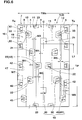
- FIG. 6 is a development view of the tread portion 2 illustrating the respective overlapping widths between axially adjacent blocks 10.
- the overlapping width W2 between the second central block 22 and the third central block 23, for example, is preferably greater than the overlapping width W1 between the first central block 21 and the second central block 22 in order to stabilize the transient characteristic when cornering at a small camber angle.
- the overlapping width W4 between the first middle block 31 and the second middle block 32 is preferably greater than the overlapping width W3 between the first middle block 31 and the third central block 23.
- the overlapping width W6 between the inner shoulder block 41 and the outer shoulder block 42 is preferably greater than the overlapping width W5 between the inner shoulder block 41 and the third middle block 33 in order to stabilize the transient characteristic when cornering at a large camber angle.
- the overlapping width W4 between the first middle block 31 and the second middle block 32 is preferably greater than the overlapping width W1 between the first central block 21 and the second central block 22.
- Such a block arrangement may provide a linear transient characteristic from straight running to the maximum leaning in cornering.
- the overlapping widths of blocks 10 are not particularly limited, but are preferably in a range of from 1% to 10% the tread development width TWe.
- the circumferential length L1 between the first central block 21 and the second central block 22 is set in a range of not less than 0.25 times, more preferably not less than 0.30 times, but preferably not more than 0.40 times, more preferably not more than 0.35 times the pitch length Lp of the block groups 7.
- Such an arrangement of the first central block 21 and the second central block 22 may offer excellent grip performance not only on a relatively hard soil ground but also on soft mud ground.
- the tread portion 2 further includes a triangular arrangement of blocks 16.
- the blocks 16 include two outer shoulder blocks 42 and 42 arranged separately in the circumferential direction of the tire to form a circumferential gap 17 therebetween, and one third middle block 33 arranged axially inward of the gap 17.
- the triangular arrangement of blocks 16 may hold mud or soil therein effectively to enhance grip performance on soft ground.
- each outer shoulder block 42 preferably has an axial width gradually decreasing toward the gap 17.
- mud and/or soil on captured in the gap 17 may be compressed strongly and sheared by the blocks 16 to generate large traction on cornering.
- tie-bars 18 are provided in a triangular manner to connect the triangular arrangement blocks 16.
- Each tie-bar 18 is provided by raising its groove bottom.
- the respective tie-bars 18 may enhance rigidity of the blocks connected one another and prevent clogging mud thereto.
- each block 10 any shapes and configurations may be employed.
- each block 10 except the first central blocks 21 is configured as a grooved block 43 having a groove on its ground contact face.
- FIG 7A illustrates an enlarged view of the ground contact face of the grooved block 43.
- the grooved block 43 for example, is provided with a pair of axially extending first grooves 45 and 45, and a second groove 46 communicating between the first grooves 45 and 45 to define an internal block piece 19.
- the respective first and second grooves 45 and 46 may increase the length of edge components on the ground contact face of the block so as to improve grip on hard terrain.
- the second groove 46 for example, has the width W10 greater than the width W9 of the first grooves 45.
- the internal block piece 19 tends to deform or move easily in the axial direction during traveling. This movement of the internal block piece 19 may be useful as a self cleaning feature of the grooves so as to push away the mud clogged in the grooves 45 and 46.
- FIG. 7B illustrates a cross-sectional view of the grooved block 43 taken along a line A-A of FIG. 7A .
- the depth d2 of the second groove 46 is preferably greater than the depth d1 of the first groove 45 in order to further improve the above advantageous effect.
- the outer shoulder block 42 formed as the grooved block 43 preferably has the ground contact face having a circumferential length gradually decreasing axially inwardly.
- the outer shoulder block 42 may improve traction on soft mud terrain by pushing away the mud.
- the outer shoulder blocks 42 also include a dented shoulder block 44 having an axially inner sidewall 47 which is dented.
- the dented shoulder block 44 may scoop mud in the dented inner sidewall 47 to improve grip performance during cornering on mud terrain.
- the land ratio Lt of the entire tread portion 2 is preferably in a range of not less than 14%, more preferably not less than 16%, but preferably not more than 21%, more preferably not more than 19%.
- the land ratio is a ratio of a net ground contacting area Sb to a gross ground contacting area St of the tread portion 2 which is obtained by plugging up the all grooves.
- the land ratio Lc of the central region 3 is in a range of not less than 11%, more preferably not less than 12%, but preferably not more than 15%, more preferably not more than 14% in order to improve grip performance on hard and soft terrain.
- each land portion Lm of each middle region 4 is 2 to 5 percentage points, more preferably 3 to 4 percentage points greater than the land ratio Lc of the central region 3 in order to stabilize transient characteristic during cornering with a small camber angle.
- each land ratio Ls of each shoulder region 5 is greater than the land ratio Lc of the central region 3 and the land ratio Lm of the middle region 4.
- the land ratio Ls of the shoulder region 5 is 8 to 11 percentage point greater than the land ratio Lc of the central region 3, and 5 to 7 percentage points greater than the land ratio Lm of the middle region 4.
- FIG. 8 illustrates a development view of the tread portion 2 of the motorcycle tire 1 for running on rough terrain according to another embodiment of the present invention.
- one of the first central blocks 21 overlaps with one of the second central blocks 22 one another when these blocks 21 and 22 are projected on a tire meridian cross section by the respective sidewalls 13 as illustrated in FIG. 3A .
- Such a block arrangement may allow the first central blocks 21 to bite into a soft mud terrain.
Landscapes
- Engineering & Computer Science (AREA)
- Mechanical Engineering (AREA)
- Tires In General (AREA)
Applications Claiming Priority (1)
| Application Number | Priority Date | Filing Date | Title |
|---|---|---|---|
| JP2015012391A JP6420674B2 (ja) | 2015-01-26 | 2015-01-26 | 不整地走行用の自動二輪車用タイヤ |
Publications (2)
| Publication Number | Publication Date |
|---|---|
| EP3047982A1 true EP3047982A1 (fr) | 2016-07-27 |
| EP3047982B1 EP3047982B1 (fr) | 2018-06-13 |
Family
ID=55177809
Family Applications (1)
| Application Number | Title | Priority Date | Filing Date |
|---|---|---|---|
| EP16151773.5A Active EP3047982B1 (fr) | 2015-01-26 | 2016-01-19 | Pneu de motocyclette pour terrains accidentés |
Country Status (4)
| Country | Link |
|---|---|
| US (1) | US10562354B2 (fr) |
| EP (1) | EP3047982B1 (fr) |
| JP (1) | JP6420674B2 (fr) |
| CN (1) | CN105818616B (fr) |
Cited By (2)
| Publication number | Priority date | Publication date | Assignee | Title |
|---|---|---|---|---|
| EP3323641A1 (fr) * | 2016-11-22 | 2018-05-23 | Sumitomo Rubber Industries, Ltd. | Pneu de motocyclette pour terrains accidentés |
| EP3524442A1 (fr) * | 2018-02-08 | 2019-08-14 | Sumitomo Rubber Industries, Ltd. | Pneu de véhicule à deux roues |
Families Citing this family (5)
| Publication number | Priority date | Publication date | Assignee | Title |
|---|---|---|---|---|
| JP6420674B2 (ja) * | 2015-01-26 | 2018-11-07 | 住友ゴム工業株式会社 | 不整地走行用の自動二輪車用タイヤ |
| JP7040064B2 (ja) * | 2018-01-31 | 2022-03-23 | 住友ゴム工業株式会社 | 不整地走行用の二輪車用タイヤ |
| WO2019157101A1 (fr) * | 2018-02-06 | 2019-08-15 | Orbis Wheels, Inc. | Véhicule terrestre |
| JP7070233B2 (ja) * | 2018-08-17 | 2022-05-18 | 住友ゴム工業株式会社 | 不整地走行用のタイヤ |
| CN109050171B (zh) * | 2018-09-04 | 2023-07-18 | 赛轮集团股份有限公司 | 越野轮胎 |
Citations (4)
| Publication number | Priority date | Publication date | Assignee | Title |
|---|---|---|---|---|
| EP2412546A1 (fr) * | 2010-07-26 | 2012-02-01 | Sumitomo Rubber Industries, Ltd. | Pneu de motocyclette pour terrains accidentés |
| EP2529954A1 (fr) * | 2011-05-30 | 2012-12-05 | Sumitomo Rubber Industries, Ltd. | Profil de bande de roulement de pneu de moto tout terrains |
| JP2014141163A (ja) | 2013-01-23 | 2014-08-07 | Sumitomo Rubber Ind Ltd | 不整地走行用の自動二輪車用タイヤ |
| EP2965926A1 (fr) * | 2014-06-17 | 2016-01-13 | Sumitomo Rubber Industries, Ltd. | Pneu de moto pour terrain accidenté |
Family Cites Families (34)
| Publication number | Priority date | Publication date | Assignee | Title |
|---|---|---|---|---|
| US4425954A (en) * | 1981-04-20 | 1984-01-17 | Motor Wheel Corporation | Method and apparatus for mounting tires on rims |
| JP4037629B2 (ja) * | 2001-08-31 | 2008-01-23 | 住友ゴム工業株式会社 | 不整地走行用の空気入りタイヤ |
| JP4808914B2 (ja) * | 2003-04-09 | 2011-11-02 | 株式会社ブリヂストン | モーターサイクルの不整地用タイヤ、及びモーターサイクルの不整地用タイヤ装着方法 |
| JP4515318B2 (ja) * | 2004-08-09 | 2010-07-28 | 住友ゴム工業株式会社 | 空気入りタイヤ |
| JP4326520B2 (ja) * | 2005-11-30 | 2009-09-09 | 住友ゴム工業株式会社 | 不整地走行用空気入りタイヤ |
| JP4921889B2 (ja) * | 2006-08-23 | 2012-04-25 | 住友ゴム工業株式会社 | 空気入りタイヤ |
| JP4287877B2 (ja) * | 2006-11-13 | 2009-07-01 | 住友ゴム工業株式会社 | 不整地走行用の空気入りタイヤ |
| JP4312226B2 (ja) * | 2006-11-15 | 2009-08-12 | 住友ゴム工業株式会社 | 不整地走行用の空気入りタイヤ |
| JP4262283B2 (ja) * | 2007-04-04 | 2009-05-13 | 住友ゴム工業株式会社 | 不整地走行用の自動二輪車用タイヤ |
| JP4328371B2 (ja) * | 2007-07-24 | 2009-09-09 | 株式会社ブリヂストン | 自動二輪車用空気入りタイヤ |
| JP4272244B2 (ja) * | 2007-09-13 | 2009-06-03 | 住友ゴム工業株式会社 | 不整地走行用空気入りタイヤ |
| JP5154972B2 (ja) * | 2008-02-19 | 2013-02-27 | 株式会社ブリヂストン | 二輪車用空気入りタイヤ |
| JP2010173459A (ja) * | 2009-01-29 | 2010-08-12 | Bridgestone Corp | 自動二輪車用タイヤ |
| JP4814980B2 (ja) * | 2009-06-17 | 2011-11-16 | 住友ゴム工業株式会社 | 不整地走行用の空気入りタイヤ |
| JP5161933B2 (ja) * | 2010-07-28 | 2013-03-13 | 住友ゴム工業株式会社 | 不整地走行用の自動二輪車用タイヤ |
| JP5174095B2 (ja) * | 2010-07-29 | 2013-04-03 | 住友ゴム工業株式会社 | 不整地走行用の自動二輪車用タイヤ |
| JP5039191B2 (ja) * | 2010-08-26 | 2012-10-03 | 住友ゴム工業株式会社 | 不整地走行用の自動二輪車用タイヤ |
| JP5174142B2 (ja) * | 2010-12-27 | 2013-04-03 | 住友ゴム工業株式会社 | 不整地走行用の自動二輪車用タイヤ |
| JP5450515B2 (ja) * | 2011-06-10 | 2014-03-26 | 住友ゴム工業株式会社 | 不整地用モーターサイクルタイヤ |
| JP5320491B2 (ja) * | 2011-07-13 | 2013-10-23 | 住友ゴム工業株式会社 | 不整地走行用の自動二輪車用タイヤ |
| JP5480868B2 (ja) * | 2011-10-07 | 2014-04-23 | 住友ゴム工業株式会社 | 空気入りタイヤ |
| JP5863456B2 (ja) * | 2011-12-29 | 2016-02-16 | 住友ゴム工業株式会社 | 不整地用モーターサイクルタイヤ |
| JP5827575B2 (ja) * | 2012-01-23 | 2015-12-02 | 住友ゴム工業株式会社 | 不整地走行用の自動二輪車用タイヤ |
| JP5616924B2 (ja) * | 2012-04-27 | 2014-10-29 | 住友ゴム工業株式会社 | 不整地走行用の空気入りタイヤ |
| JP5564071B2 (ja) * | 2012-05-18 | 2014-07-30 | 住友ゴム工業株式会社 | 不整地走行用の自動二輪車用タイヤ |
| JP5629293B2 (ja) * | 2012-08-09 | 2014-11-19 | 住友ゴム工業株式会社 | 不整地走行用の空気入りタイヤ |
| CN202782523U (zh) * | 2012-09-28 | 2013-03-13 | 厦门正新橡胶工业有限公司 | 一种用于摩托车越野赛的充气轮胎 |
| JP5802223B2 (ja) * | 2013-01-30 | 2015-10-28 | 住友ゴム工業株式会社 | 不整地走行用の自動二輪車用タイヤ |
| JP5870062B2 (ja) * | 2013-04-11 | 2016-02-24 | 住友ゴム工業株式会社 | 自動二輪車用タイヤ |
| CN203211018U (zh) * | 2013-04-18 | 2013-09-25 | 厦门正新橡胶工业有限公司 | 泥草地用摩托车轮胎胎面结构 |
| JP6328416B2 (ja) * | 2013-12-13 | 2018-05-23 | 株式会社ブリヂストン | 自動二輪車用タイヤ |
| JP1519925S (fr) * | 2014-09-03 | 2015-03-23 | ||
| JP6097263B2 (ja) * | 2014-09-25 | 2017-03-15 | 住友ゴム工業株式会社 | 空気入りタイヤ |
| JP6420674B2 (ja) * | 2015-01-26 | 2018-11-07 | 住友ゴム工業株式会社 | 不整地走行用の自動二輪車用タイヤ |
-
2015
- 2015-01-26 JP JP2015012391A patent/JP6420674B2/ja active Active
-
2016
- 2016-01-15 CN CN201610027815.8A patent/CN105818616B/zh active Active
- 2016-01-19 EP EP16151773.5A patent/EP3047982B1/fr active Active
- 2016-01-22 US US15/003,910 patent/US10562354B2/en active Active
Patent Citations (4)
| Publication number | Priority date | Publication date | Assignee | Title |
|---|---|---|---|---|
| EP2412546A1 (fr) * | 2010-07-26 | 2012-02-01 | Sumitomo Rubber Industries, Ltd. | Pneu de motocyclette pour terrains accidentés |
| EP2529954A1 (fr) * | 2011-05-30 | 2012-12-05 | Sumitomo Rubber Industries, Ltd. | Profil de bande de roulement de pneu de moto tout terrains |
| JP2014141163A (ja) | 2013-01-23 | 2014-08-07 | Sumitomo Rubber Ind Ltd | 不整地走行用の自動二輪車用タイヤ |
| EP2965926A1 (fr) * | 2014-06-17 | 2016-01-13 | Sumitomo Rubber Industries, Ltd. | Pneu de moto pour terrain accidenté |
Cited By (4)
| Publication number | Priority date | Publication date | Assignee | Title |
|---|---|---|---|---|
| EP3323641A1 (fr) * | 2016-11-22 | 2018-05-23 | Sumitomo Rubber Industries, Ltd. | Pneu de motocyclette pour terrains accidentés |
| US10899180B2 (en) | 2016-11-22 | 2021-01-26 | Sumitomo Rubber Industries, Ltd. | Motorcycle tire for running on rough terrain |
| EP3524442A1 (fr) * | 2018-02-08 | 2019-08-14 | Sumitomo Rubber Industries, Ltd. | Pneu de véhicule à deux roues |
| US11607914B2 (en) | 2018-02-08 | 2023-03-21 | Sumitomo Rubber Industries, Ltd. | Two-wheeled vehicle tire |
Also Published As
| Publication number | Publication date |
|---|---|
| US10562354B2 (en) | 2020-02-18 |
| CN105818616A (zh) | 2016-08-03 |
| US20160214439A1 (en) | 2016-07-28 |
| CN105818616B (zh) | 2019-07-26 |
| JP6420674B2 (ja) | 2018-11-07 |
| EP3047982B1 (fr) | 2018-06-13 |
| JP2016137750A (ja) | 2016-08-04 |
Similar Documents
| Publication | Publication Date | Title |
|---|---|---|
| EP3047982A1 (fr) | Pneu de motocyclette pour terrains accidentés | |
| JP5965138B2 (ja) | 自動二輪車用空気入りタイヤ | |
| JP5797506B2 (ja) | 空気入りタイヤ | |
| US20160325590A1 (en) | Tire With Grooves Having Variable Depth | |
| JP2014141163A (ja) | 不整地走行用の自動二輪車用タイヤ | |
| JP6958327B2 (ja) | 不整地走行用の自動二輪車用タイヤ | |
| JP6061855B2 (ja) | 農業機械用タイヤ | |
| WO2015133054A1 (fr) | Bandage pneumatique | |
| JP2018083585A (ja) | 不整地走行用のタイヤ | |
| JP2000225815A (ja) | 空気入りタイヤ | |
| JP6328416B2 (ja) | 自動二輪車用タイヤ | |
| JP2018103673A (ja) | タイヤ | |
| CN110834496B (zh) | 不平整地面行驶用的轮胎 | |
| JP6790098B2 (ja) | 大型トラックタイヤトレッド及び大型トラックタイヤ | |
| JP2009018617A (ja) | 空気入りタイヤ | |
| CN110871650B (zh) | 不平整地行驶用的摩托车用轮胎 | |
| JP2016074366A (ja) | 自動二輪車用タイヤ | |
| JP7087427B2 (ja) | 二輪車用タイヤ | |
| US10899180B2 (en) | Motorcycle tire for running on rough terrain | |
| JP5738566B2 (ja) | 農業用タイヤ | |
| JP7404820B2 (ja) | 不整地走行用の二輪車用タイヤ | |
| JP2011189809A (ja) | 自動二輪車用空気入りタイヤ | |
| JP2011143795A (ja) | 空気入りタイヤ | |
| JP6158594B2 (ja) | タイヤ | |
| JP4627708B2 (ja) | 重荷重用ラジアルタイヤ |
Legal Events
| Date | Code | Title | Description |
|---|---|---|---|
| PUAI | Public reference made under article 153(3) epc to a published international application that has entered the european phase |
Free format text: ORIGINAL CODE: 0009012 |
|
| AK | Designated contracting states |
Kind code of ref document: A1 Designated state(s): AL AT BE BG CH CY CZ DE DK EE ES FI FR GB GR HR HU IE IS IT LI LT LU LV MC MK MT NL NO PL PT RO RS SE SI SK SM TR |
|
| AX | Request for extension of the european patent |
Extension state: BA ME |
|
| STAA | Information on the status of an ep patent application or granted ep patent |
Free format text: STATUS: REQUEST FOR EXAMINATION WAS MADE |
|
| 17P | Request for examination filed |
Effective date: 20161129 |
|
| RBV | Designated contracting states (corrected) |
Designated state(s): AL AT BE BG CH CY CZ DE DK EE ES FI FR GB GR HR HU IE IS IT LI LT LU LV MC MK MT NL NO PL PT RO RS SE SI SK SM TR |
|
| RIC1 | Information provided on ipc code assigned before grant |
Ipc: B60C 11/03 20060101ALI20180206BHEP Ipc: B60C 11/11 20060101AFI20180206BHEP Ipc: B60C 11/13 20060101ALI20180206BHEP |
|
| GRAP | Despatch of communication of intention to grant a patent |
Free format text: ORIGINAL CODE: EPIDOSNIGR1 |
|
| STAA | Information on the status of an ep patent application or granted ep patent |
Free format text: STATUS: GRANT OF PATENT IS INTENDED |
|
| INTG | Intention to grant announced |
Effective date: 20180316 |
|
| RAP1 | Party data changed (applicant data changed or rights of an application transferred) |
Owner name: SUMITOMO RUBBER INDUSTRIES, LTD. |
|
| GRAS | Grant fee paid |
Free format text: ORIGINAL CODE: EPIDOSNIGR3 |
|
| GRAA | (expected) grant |
Free format text: ORIGINAL CODE: 0009210 |
|
| STAA | Information on the status of an ep patent application or granted ep patent |
Free format text: STATUS: THE PATENT HAS BEEN GRANTED |
|
| AK | Designated contracting states |
Kind code of ref document: B1 Designated state(s): AL AT BE BG CH CY CZ DE DK EE ES FI FR GB GR HR HU IE IS IT LI LT LU LV MC MK MT NL NO PL PT RO RS SE SI SK SM TR |
|
| REG | Reference to a national code |
Ref country code: GB Ref legal event code: FG4D |
|
| REG | Reference to a national code |
Ref country code: CH Ref legal event code: EP Ref country code: AT Ref legal event code: REF Ref document number: 1008090 Country of ref document: AT Kind code of ref document: T Effective date: 20180615 |
|
| REG | Reference to a national code |
Ref country code: IE Ref legal event code: FG4D |
|
| REG | Reference to a national code |
Ref country code: DE Ref legal event code: R096 Ref document number: 602016003402 Country of ref document: DE |
|
| REG | Reference to a national code |
Ref country code: NL Ref legal event code: MP Effective date: 20180613 |
|
| REG | Reference to a national code |
Ref country code: LT Ref legal event code: MG4D |
|
| PG25 | Lapsed in a contracting state [announced via postgrant information from national office to epo] |
Ref country code: ES Free format text: LAPSE BECAUSE OF FAILURE TO SUBMIT A TRANSLATION OF THE DESCRIPTION OR TO PAY THE FEE WITHIN THE PRESCRIBED TIME-LIMIT Effective date: 20180613 Ref country code: LT Free format text: LAPSE BECAUSE OF FAILURE TO SUBMIT A TRANSLATION OF THE DESCRIPTION OR TO PAY THE FEE WITHIN THE PRESCRIBED TIME-LIMIT Effective date: 20180613 Ref country code: CY Free format text: LAPSE BECAUSE OF FAILURE TO SUBMIT A TRANSLATION OF THE DESCRIPTION OR TO PAY THE FEE WITHIN THE PRESCRIBED TIME-LIMIT Effective date: 20180613 Ref country code: BG Free format text: LAPSE BECAUSE OF FAILURE TO SUBMIT A TRANSLATION OF THE DESCRIPTION OR TO PAY THE FEE WITHIN THE PRESCRIBED TIME-LIMIT Effective date: 20180913 Ref country code: FI Free format text: LAPSE BECAUSE OF FAILURE TO SUBMIT A TRANSLATION OF THE DESCRIPTION OR TO PAY THE FEE WITHIN THE PRESCRIBED TIME-LIMIT Effective date: 20180613 Ref country code: NO Free format text: LAPSE BECAUSE OF FAILURE TO SUBMIT A TRANSLATION OF THE DESCRIPTION OR TO PAY THE FEE WITHIN THE PRESCRIBED TIME-LIMIT Effective date: 20180913 Ref country code: SE Free format text: LAPSE BECAUSE OF FAILURE TO SUBMIT A TRANSLATION OF THE DESCRIPTION OR TO PAY THE FEE WITHIN THE PRESCRIBED TIME-LIMIT Effective date: 20180613 |
|
| PG25 | Lapsed in a contracting state [announced via postgrant information from national office to epo] |
Ref country code: HR Free format text: LAPSE BECAUSE OF FAILURE TO SUBMIT A TRANSLATION OF THE DESCRIPTION OR TO PAY THE FEE WITHIN THE PRESCRIBED TIME-LIMIT Effective date: 20180613 Ref country code: GR Free format text: LAPSE BECAUSE OF FAILURE TO SUBMIT A TRANSLATION OF THE DESCRIPTION OR TO PAY THE FEE WITHIN THE PRESCRIBED TIME-LIMIT Effective date: 20180914 Ref country code: LV Free format text: LAPSE BECAUSE OF FAILURE TO SUBMIT A TRANSLATION OF THE DESCRIPTION OR TO PAY THE FEE WITHIN THE PRESCRIBED TIME-LIMIT Effective date: 20180613 Ref country code: RS Free format text: LAPSE BECAUSE OF FAILURE TO SUBMIT A TRANSLATION OF THE DESCRIPTION OR TO PAY THE FEE WITHIN THE PRESCRIBED TIME-LIMIT Effective date: 20180613 |
|
| REG | Reference to a national code |
Ref country code: AT Ref legal event code: MK05 Ref document number: 1008090 Country of ref document: AT Kind code of ref document: T Effective date: 20180613 |
|
| PG25 | Lapsed in a contracting state [announced via postgrant information from national office to epo] |
Ref country code: NL Free format text: LAPSE BECAUSE OF FAILURE TO SUBMIT A TRANSLATION OF THE DESCRIPTION OR TO PAY THE FEE WITHIN THE PRESCRIBED TIME-LIMIT Effective date: 20180613 |
|
| PG25 | Lapsed in a contracting state [announced via postgrant information from national office to epo] |
Ref country code: RO Free format text: LAPSE BECAUSE OF FAILURE TO SUBMIT A TRANSLATION OF THE DESCRIPTION OR TO PAY THE FEE WITHIN THE PRESCRIBED TIME-LIMIT Effective date: 20180613 Ref country code: SK Free format text: LAPSE BECAUSE OF FAILURE TO SUBMIT A TRANSLATION OF THE DESCRIPTION OR TO PAY THE FEE WITHIN THE PRESCRIBED TIME-LIMIT Effective date: 20180613 Ref country code: CZ Free format text: LAPSE BECAUSE OF FAILURE TO SUBMIT A TRANSLATION OF THE DESCRIPTION OR TO PAY THE FEE WITHIN THE PRESCRIBED TIME-LIMIT Effective date: 20180613 Ref country code: PL Free format text: LAPSE BECAUSE OF FAILURE TO SUBMIT A TRANSLATION OF THE DESCRIPTION OR TO PAY THE FEE WITHIN THE PRESCRIBED TIME-LIMIT Effective date: 20180613 Ref country code: IS Free format text: LAPSE BECAUSE OF FAILURE TO SUBMIT A TRANSLATION OF THE DESCRIPTION OR TO PAY THE FEE WITHIN THE PRESCRIBED TIME-LIMIT Effective date: 20181013 Ref country code: EE Free format text: LAPSE BECAUSE OF FAILURE TO SUBMIT A TRANSLATION OF THE DESCRIPTION OR TO PAY THE FEE WITHIN THE PRESCRIBED TIME-LIMIT Effective date: 20180613 Ref country code: AT Free format text: LAPSE BECAUSE OF FAILURE TO SUBMIT A TRANSLATION OF THE DESCRIPTION OR TO PAY THE FEE WITHIN THE PRESCRIBED TIME-LIMIT Effective date: 20180613 |
|
| PG25 | Lapsed in a contracting state [announced via postgrant information from national office to epo] |
Ref country code: IT Free format text: LAPSE BECAUSE OF FAILURE TO SUBMIT A TRANSLATION OF THE DESCRIPTION OR TO PAY THE FEE WITHIN THE PRESCRIBED TIME-LIMIT Effective date: 20180613 Ref country code: SM Free format text: LAPSE BECAUSE OF FAILURE TO SUBMIT A TRANSLATION OF THE DESCRIPTION OR TO PAY THE FEE WITHIN THE PRESCRIBED TIME-LIMIT Effective date: 20180613 |
|
| REG | Reference to a national code |
Ref country code: DE Ref legal event code: R097 Ref document number: 602016003402 Country of ref document: DE |
|
| PLBE | No opposition filed within time limit |
Free format text: ORIGINAL CODE: 0009261 |
|
| STAA | Information on the status of an ep patent application or granted ep patent |
Free format text: STATUS: NO OPPOSITION FILED WITHIN TIME LIMIT |
|
| 26N | No opposition filed |
Effective date: 20190314 |
|
| PG25 | Lapsed in a contracting state [announced via postgrant information from national office to epo] |
Ref country code: DK Free format text: LAPSE BECAUSE OF FAILURE TO SUBMIT A TRANSLATION OF THE DESCRIPTION OR TO PAY THE FEE WITHIN THE PRESCRIBED TIME-LIMIT Effective date: 20180613 Ref country code: SI Free format text: LAPSE BECAUSE OF FAILURE TO SUBMIT A TRANSLATION OF THE DESCRIPTION OR TO PAY THE FEE WITHIN THE PRESCRIBED TIME-LIMIT Effective date: 20180613 |
|
| PG25 | Lapsed in a contracting state [announced via postgrant information from national office to epo] |
Ref country code: MC Free format text: LAPSE BECAUSE OF FAILURE TO SUBMIT A TRANSLATION OF THE DESCRIPTION OR TO PAY THE FEE WITHIN THE PRESCRIBED TIME-LIMIT Effective date: 20180613 |
|
| REG | Reference to a national code |
Ref country code: CH Ref legal event code: PL |
|
| PG25 | Lapsed in a contracting state [announced via postgrant information from national office to epo] |
Ref country code: LU Free format text: LAPSE BECAUSE OF NON-PAYMENT OF DUE FEES Effective date: 20190119 |
|
| REG | Reference to a national code |
Ref country code: BE Ref legal event code: MM Effective date: 20190131 |
|
| REG | Reference to a national code |
Ref country code: IE Ref legal event code: MM4A |
|
| PG25 | Lapsed in a contracting state [announced via postgrant information from national office to epo] |
Ref country code: AL Free format text: LAPSE BECAUSE OF FAILURE TO SUBMIT A TRANSLATION OF THE DESCRIPTION OR TO PAY THE FEE WITHIN THE PRESCRIBED TIME-LIMIT Effective date: 20180613 Ref country code: BE Free format text: LAPSE BECAUSE OF NON-PAYMENT OF DUE FEES Effective date: 20190131 |
|
| PG25 | Lapsed in a contracting state [announced via postgrant information from national office to epo] |
Ref country code: CH Free format text: LAPSE BECAUSE OF NON-PAYMENT OF DUE FEES Effective date: 20190131 Ref country code: LI Free format text: LAPSE BECAUSE OF NON-PAYMENT OF DUE FEES Effective date: 20190131 |
|
| PG25 | Lapsed in a contracting state [announced via postgrant information from national office to epo] |
Ref country code: IE Free format text: LAPSE BECAUSE OF NON-PAYMENT OF DUE FEES Effective date: 20190119 |
|
| PG25 | Lapsed in a contracting state [announced via postgrant information from national office to epo] |
Ref country code: TR Free format text: LAPSE BECAUSE OF FAILURE TO SUBMIT A TRANSLATION OF THE DESCRIPTION OR TO PAY THE FEE WITHIN THE PRESCRIBED TIME-LIMIT Effective date: 20180613 |
|
| PG25 | Lapsed in a contracting state [announced via postgrant information from national office to epo] |
Ref country code: PT Free format text: LAPSE BECAUSE OF FAILURE TO SUBMIT A TRANSLATION OF THE DESCRIPTION OR TO PAY THE FEE WITHIN THE PRESCRIBED TIME-LIMIT Effective date: 20181015 Ref country code: MT Free format text: LAPSE BECAUSE OF NON-PAYMENT OF DUE FEES Effective date: 20190119 |
|
| GBPC | Gb: european patent ceased through non-payment of renewal fee |
Effective date: 20200119 |
|
| PG25 | Lapsed in a contracting state [announced via postgrant information from national office to epo] |
Ref country code: GB Free format text: LAPSE BECAUSE OF NON-PAYMENT OF DUE FEES Effective date: 20200119 |
|
| PG25 | Lapsed in a contracting state [announced via postgrant information from national office to epo] |
Ref country code: HU Free format text: LAPSE BECAUSE OF FAILURE TO SUBMIT A TRANSLATION OF THE DESCRIPTION OR TO PAY THE FEE WITHIN THE PRESCRIBED TIME-LIMIT; INVALID AB INITIO Effective date: 20160119 |
|
| PG25 | Lapsed in a contracting state [announced via postgrant information from national office to epo] |
Ref country code: MK Free format text: LAPSE BECAUSE OF FAILURE TO SUBMIT A TRANSLATION OF THE DESCRIPTION OR TO PAY THE FEE WITHIN THE PRESCRIBED TIME-LIMIT Effective date: 20180613 |
|
| PGFP | Annual fee paid to national office [announced via postgrant information from national office to epo] |
Ref country code: FR Payment date: 20251128 Year of fee payment: 11 |
|
| PGFP | Annual fee paid to national office [announced via postgrant information from national office to epo] |
Ref country code: DE Payment date: 20251203 Year of fee payment: 11 |