EP3048002B1 - Dispositif de régulation du glissement d'un véhicule électrique - Google Patents
Dispositif de régulation du glissement d'un véhicule électrique Download PDFInfo
- Publication number
- EP3048002B1 EP3048002B1 EP14845633.8A EP14845633A EP3048002B1 EP 3048002 B1 EP3048002 B1 EP 3048002B1 EP 14845633 A EP14845633 A EP 14845633A EP 3048002 B1 EP3048002 B1 EP 3048002B1
- Authority
- EP
- European Patent Office
- Prior art keywords
- rotations
- section
- slip
- drive wheel
- slip control
- Prior art date
- Legal status (The legal status is an assumption and is not a legal conclusion. Google has not performed a legal analysis and makes no representation as to the accuracy of the status listed.)
- Not-in-force
Links
Images



Classifications
-
- B—PERFORMING OPERATIONS; TRANSPORTING
- B60—VEHICLES IN GENERAL
- B60L—PROPULSION OF ELECTRICALLY-PROPELLED VEHICLES; SUPPLYING ELECTRIC POWER FOR AUXILIARY EQUIPMENT OF ELECTRICALLY-PROPELLED VEHICLES; ELECTRODYNAMIC BRAKE SYSTEMS FOR VEHICLES IN GENERAL; MAGNETIC SUSPENSION OR LEVITATION FOR VEHICLES; MONITORING OPERATING VARIABLES OF ELECTRICALLY-PROPELLED VEHICLES; ELECTRIC SAFETY DEVICES FOR ELECTRICALLY-PROPELLED VEHICLES
- B60L3/00—Electric devices on electrically-propelled vehicles for safety purposes; Monitoring operating variables, e.g. speed, deceleration or energy consumption
- B60L3/10—Indicating wheel slip ; Correction of wheel slip
- B60L3/102—Indicating wheel slip ; Correction of wheel slip of individual wheels
-
- B—PERFORMING OPERATIONS; TRANSPORTING
- B60—VEHICLES IN GENERAL
- B60K—ARRANGEMENT OR MOUNTING OF PROPULSION UNITS OR OF TRANSMISSIONS IN VEHICLES; ARRANGEMENT OR MOUNTING OF PLURAL DIVERSE PRIME-MOVERS IN VEHICLES; AUXILIARY DRIVES FOR VEHICLES; INSTRUMENTATION OR DASHBOARDS FOR VEHICLES; ARRANGEMENTS IN CONNECTION WITH COOLING, AIR INTAKE, GAS EXHAUST OR FUEL SUPPLY OF PROPULSION UNITS IN VEHICLES
- B60K28/00—Safety devices for propulsion-unit control, specially adapted for, or arranged in, vehicles, e.g. preventing fuel supply or ignition in the event of potentially dangerous conditions
- B60K28/10—Safety devices for propulsion-unit control, specially adapted for, or arranged in, vehicles, e.g. preventing fuel supply or ignition in the event of potentially dangerous conditions responsive to conditions relating to the vehicle
- B60K28/16—Safety devices for propulsion-unit control, specially adapted for, or arranged in, vehicles, e.g. preventing fuel supply or ignition in the event of potentially dangerous conditions responsive to conditions relating to the vehicle responsive to, or preventing, spinning or skidding of wheels
-
- B—PERFORMING OPERATIONS; TRANSPORTING
- B60—VEHICLES IN GENERAL
- B60L—PROPULSION OF ELECTRICALLY-PROPELLED VEHICLES; SUPPLYING ELECTRIC POWER FOR AUXILIARY EQUIPMENT OF ELECTRICALLY-PROPELLED VEHICLES; ELECTRODYNAMIC BRAKE SYSTEMS FOR VEHICLES IN GENERAL; MAGNETIC SUSPENSION OR LEVITATION FOR VEHICLES; MONITORING OPERATING VARIABLES OF ELECTRICALLY-PROPELLED VEHICLES; ELECTRIC SAFETY DEVICES FOR ELECTRICALLY-PROPELLED VEHICLES
- B60L15/00—Methods, circuits, or devices for controlling the traction-motor speed of electrically-propelled vehicles
- B60L15/20—Methods, circuits, or devices for controlling the traction-motor speed of electrically-propelled vehicles for control of the vehicle or its driving motor to achieve a desired performance, e.g. speed, torque, programmed variation of speed
-
- B—PERFORMING OPERATIONS; TRANSPORTING
- B60—VEHICLES IN GENERAL
- B60L—PROPULSION OF ELECTRICALLY-PROPELLED VEHICLES; SUPPLYING ELECTRIC POWER FOR AUXILIARY EQUIPMENT OF ELECTRICALLY-PROPELLED VEHICLES; ELECTRODYNAMIC BRAKE SYSTEMS FOR VEHICLES IN GENERAL; MAGNETIC SUSPENSION OR LEVITATION FOR VEHICLES; MONITORING OPERATING VARIABLES OF ELECTRICALLY-PROPELLED VEHICLES; ELECTRIC SAFETY DEVICES FOR ELECTRICALLY-PROPELLED VEHICLES
- B60L2220/00—Electrical machine types; Structures or applications thereof
- B60L2220/40—Electrical machine applications
- B60L2220/44—Wheel Hub motors, i.e. integrated in the wheel hub
-
- B—PERFORMING OPERATIONS; TRANSPORTING
- B60—VEHICLES IN GENERAL
- B60L—PROPULSION OF ELECTRICALLY-PROPELLED VEHICLES; SUPPLYING ELECTRIC POWER FOR AUXILIARY EQUIPMENT OF ELECTRICALLY-PROPELLED VEHICLES; ELECTRODYNAMIC BRAKE SYSTEMS FOR VEHICLES IN GENERAL; MAGNETIC SUSPENSION OR LEVITATION FOR VEHICLES; MONITORING OPERATING VARIABLES OF ELECTRICALLY-PROPELLED VEHICLES; ELECTRIC SAFETY DEVICES FOR ELECTRICALLY-PROPELLED VEHICLES
- B60L2220/00—Electrical machine types; Structures or applications thereof
- B60L2220/40—Electrical machine applications
- B60L2220/46—Wheel motors, i.e. motor connected to only one wheel
-
- B—PERFORMING OPERATIONS; TRANSPORTING
- B60—VEHICLES IN GENERAL
- B60L—PROPULSION OF ELECTRICALLY-PROPELLED VEHICLES; SUPPLYING ELECTRIC POWER FOR AUXILIARY EQUIPMENT OF ELECTRICALLY-PROPELLED VEHICLES; ELECTRODYNAMIC BRAKE SYSTEMS FOR VEHICLES IN GENERAL; MAGNETIC SUSPENSION OR LEVITATION FOR VEHICLES; MONITORING OPERATING VARIABLES OF ELECTRICALLY-PROPELLED VEHICLES; ELECTRIC SAFETY DEVICES FOR ELECTRICALLY-PROPELLED VEHICLES
- B60L2240/00—Control parameters of input or output; Target parameters
- B60L2240/10—Vehicle control parameters
- B60L2240/12—Speed
-
- B—PERFORMING OPERATIONS; TRANSPORTING
- B60—VEHICLES IN GENERAL
- B60L—PROPULSION OF ELECTRICALLY-PROPELLED VEHICLES; SUPPLYING ELECTRIC POWER FOR AUXILIARY EQUIPMENT OF ELECTRICALLY-PROPELLED VEHICLES; ELECTRODYNAMIC BRAKE SYSTEMS FOR VEHICLES IN GENERAL; MAGNETIC SUSPENSION OR LEVITATION FOR VEHICLES; MONITORING OPERATING VARIABLES OF ELECTRICALLY-PROPELLED VEHICLES; ELECTRIC SAFETY DEVICES FOR ELECTRICALLY-PROPELLED VEHICLES
- B60L2240/00—Control parameters of input or output; Target parameters
- B60L2240/40—Drive Train control parameters
- B60L2240/42—Drive Train control parameters related to electric machines
- B60L2240/423—Torque
-
- B—PERFORMING OPERATIONS; TRANSPORTING
- B60—VEHICLES IN GENERAL
- B60L—PROPULSION OF ELECTRICALLY-PROPELLED VEHICLES; SUPPLYING ELECTRIC POWER FOR AUXILIARY EQUIPMENT OF ELECTRICALLY-PROPELLED VEHICLES; ELECTRODYNAMIC BRAKE SYSTEMS FOR VEHICLES IN GENERAL; MAGNETIC SUSPENSION OR LEVITATION FOR VEHICLES; MONITORING OPERATING VARIABLES OF ELECTRICALLY-PROPELLED VEHICLES; ELECTRIC SAFETY DEVICES FOR ELECTRICALLY-PROPELLED VEHICLES
- B60L2240/00—Control parameters of input or output; Target parameters
- B60L2240/40—Drive Train control parameters
- B60L2240/46—Drive Train control parameters related to wheels
- B60L2240/461—Speed
-
- B—PERFORMING OPERATIONS; TRANSPORTING
- B60—VEHICLES IN GENERAL
- B60L—PROPULSION OF ELECTRICALLY-PROPELLED VEHICLES; SUPPLYING ELECTRIC POWER FOR AUXILIARY EQUIPMENT OF ELECTRICALLY-PROPELLED VEHICLES; ELECTRODYNAMIC BRAKE SYSTEMS FOR VEHICLES IN GENERAL; MAGNETIC SUSPENSION OR LEVITATION FOR VEHICLES; MONITORING OPERATING VARIABLES OF ELECTRICALLY-PROPELLED VEHICLES; ELECTRIC SAFETY DEVICES FOR ELECTRICALLY-PROPELLED VEHICLES
- B60L2240/00—Control parameters of input or output; Target parameters
- B60L2240/40—Drive Train control parameters
- B60L2240/46—Drive Train control parameters related to wheels
- B60L2240/465—Slip
-
- B—PERFORMING OPERATIONS; TRANSPORTING
- B60—VEHICLES IN GENERAL
- B60L—PROPULSION OF ELECTRICALLY-PROPELLED VEHICLES; SUPPLYING ELECTRIC POWER FOR AUXILIARY EQUIPMENT OF ELECTRICALLY-PROPELLED VEHICLES; ELECTRODYNAMIC BRAKE SYSTEMS FOR VEHICLES IN GENERAL; MAGNETIC SUSPENSION OR LEVITATION FOR VEHICLES; MONITORING OPERATING VARIABLES OF ELECTRICALLY-PROPELLED VEHICLES; ELECTRIC SAFETY DEVICES FOR ELECTRICALLY-PROPELLED VEHICLES
- B60L2270/00—Problem solutions or means not otherwise provided for
- B60L2270/10—Emission reduction
- B60L2270/14—Emission reduction of noise
- B60L2270/145—Structure borne vibrations
-
- B—PERFORMING OPERATIONS; TRANSPORTING
- B60—VEHICLES IN GENERAL
- B60W—CONJOINT CONTROL OF VEHICLE SUB-UNITS OF DIFFERENT TYPE OR DIFFERENT FUNCTION; CONTROL SYSTEMS SPECIALLY ADAPTED FOR HYBRID VEHICLES; ROAD VEHICLE DRIVE CONTROL SYSTEMS FOR PURPOSES NOT RELATED TO THE CONTROL OF A PARTICULAR SUB-UNIT
- B60W2720/00—Output or target parameters relating to overall vehicle dynamics
- B60W2720/26—Wheel slip
-
- Y—GENERAL TAGGING OF NEW TECHNOLOGICAL DEVELOPMENTS; GENERAL TAGGING OF CROSS-SECTIONAL TECHNOLOGIES SPANNING OVER SEVERAL SECTIONS OF THE IPC; TECHNICAL SUBJECTS COVERED BY FORMER USPC CROSS-REFERENCE ART COLLECTIONS [XRACs] AND DIGESTS
- Y02—TECHNOLOGIES OR APPLICATIONS FOR MITIGATION OR ADAPTATION AGAINST CLIMATE CHANGE
- Y02T—CLIMATE CHANGE MITIGATION TECHNOLOGIES RELATED TO TRANSPORTATION
- Y02T10/00—Road transport of goods or passengers
- Y02T10/60—Other road transportation technologies with climate change mitigation effect
- Y02T10/64—Electric machine technologies in electromobility
-
- Y—GENERAL TAGGING OF NEW TECHNOLOGICAL DEVELOPMENTS; GENERAL TAGGING OF CROSS-SECTIONAL TECHNOLOGIES SPANNING OVER SEVERAL SECTIONS OF THE IPC; TECHNICAL SUBJECTS COVERED BY FORMER USPC CROSS-REFERENCE ART COLLECTIONS [XRACs] AND DIGESTS
- Y02—TECHNOLOGIES OR APPLICATIONS FOR MITIGATION OR ADAPTATION AGAINST CLIMATE CHANGE
- Y02T—CLIMATE CHANGE MITIGATION TECHNOLOGIES RELATED TO TRANSPORTATION
- Y02T10/00—Road transport of goods or passengers
- Y02T10/60—Other road transportation technologies with climate change mitigation effect
- Y02T10/72—Electric energy management in electromobility
Definitions
- the present invention relates to a slip control device for an electric vehicle, and relates to a technique to be able to accurately perform slip control even when a vehicle speed is in a low-speed range.
- a slip ratio ⁇ is obtained by slip ratio estimation section on the basis of numbers of rotations N1 and N2 of a driven wheel and a drive wheel. Then, a generated torque estimation value Te due to another external force such as the vehicle body weight applied to the vehicle is obtained by a disturbance observer. An entire action torque T acting on the drive wheel is obtained by an action torque estimation section on the basis of the generated torque estimation value Te and a motor torque Tm, and a coefficient of friction ⁇ between a road surface and a tire is estimated by a friction coefficient estimation section on the basis of this torque and the slip ratio ⁇ .
- a permissible maximum torque Tmax is obtained on the basis of this coefficient of friction ⁇ and a vertical load FZ, and torque limitation is performed such that the torque does not exceed the permissible maximum torque Tmax.
- Patent Document 1 JP Laid-open Patent Publication No. 2012-186928
- a wheel speed sensor is an electromagnetic pickup type, and thus, for example, when the vehicle runs at a very low speed, a response cycle of the wheel speed sensor is low depending on the number of teeth of a sensor rotor and therefore cannot catch up with a control repetition cycle of a controller.
- a control repetition cycle is generally about 10 ms at present.
- the response cycle of the wheel speed sensor is 20 ms per tooth.
- the response cycle is too slow for a control repetition cycle of 10 ms of a controller used for the motor control of the electric vehicle, thereby leading to an erroneous operation of the controller.
- the response cycle increases.
- An object of the present invention is to provide a slip control device for an electric vehicle which slip control device is able to accurately perform slip control by correctly detecting the number of rotations of a wheel regardless of a vehicle speed.
- a slip control device for an electric vehicle is a slip control device 20 for an electric vehicle which is a vehicle including an electric motor 3 configured to rotationally drive a drive wheel 7, the slip control device 20 performing slip control of the electric vehicle, the slip control device 20 including:
- the "number of rotations” in the present specification is the number of rotations per unit time and is synonymous with a rotation speed.
- the phrase “decreasing a torque command” or the phrase “decreasing a torque command value” also includes causing the torque command (or torque command value) to be zero.
- the slip control section 28 determines whether or not a slip state has occurred, on the basis of the number of rotations of the drive wheel and the number of rotations of the driven wheel observed by the drive wheel rotation number observation section 23 and the driven wheel rotation number observation section 21, respectively. As a result of the determination, if the slip state has occurred, the slip control section 28 performs the series of slip control of decreasing the torque command to the motor 3, in the variable control repetition cycle. While the slip control is performed, the control repetition cycle change section 30 lengthens the control repetition cycle of the slip control section 28 when the detected vehicle speed is in the predetermined low-speed range (e.g., equal to or less than 10 km/h).
- the predetermined low-speed range e.g., equal to or less than 10 km/h.
- the response cycle of the sensor can be prevented from being too slow for the control repetition cycle of the slip control section 28. Accordingly, it is possible to prevent an erroneous operation of the slip control section 28 and to accurately detect a driven wheel number of rotations, thereby accurately performing the slip control.
- the slip control can be accurately performed by correctly detecting the number of rotations of the wheel regardless of the vehicle speed.
- a response cycle Ts of the sensor 15b which detects the to-be-detected portions is calculated by the above formula.
- the response cycle Ts of the sensor 15b which detects the to-be-detected portions 15aa becomes slow as the vehicle speed decreases.
- the response cycle Ts of the sensor 15b may be too slow for the control repetition cycle T of the slip control section 28, depending on the vehicle speed.
- control repetition cycle T of the slip control section 28 With the response cycle Ts itself of the sensor 15b corresponding to the vehicle speed, the control repetition cycle T of the slip control section 28 can be assuredly caused to coincide with the response cycle of the sensor 15b even when the vehicle speed is any speed in the low-speed range.
- the slip control section 28 may include:
- the slip ratio change section 31 changes the slip ratio ⁇ in accordance with the vehicle speed.
- the maximum rotation number calculation section 22 calculates the drive wheel maximum number of rotations with the changed slip ratio ⁇ .
- the slip state determination section 24 determines that the slip state has occurred. As a result of the determination that the slip state has occurred, the torque command to the motor 3 is decreased.
- the drive wheel maximum number of rotations is calculated with the slip ratio ⁇ 0 which serves as a reference. Then, determination as to a slip state by the slip state determination section 24 is performed similarly as described above.
- the slip control section 28 may include:
- the motor 3 may be forming an in-wheel motor device 11.
- each wheel 7 is individually driven by the motor and is greatly affected by a slip. Therefore the effect by the above slip control is more effectively exerted.
- Fig. 1 shows an electric vehicle drive apparatus including slip control devices according to the embodiment.
- the electric vehicle drive apparatus includes a VCU (vehicle control unit) 1 and inverter devices 2.
- the VCU 1 is a computer type electric control unit which performs integrated control and cooperative control of the entire vehicle, and is also referred to as "ECU".
- Each inverter device 2 is a device which converts a direct current into an alternating current.
- each inverter device 2 has a function as a controller which applies a three-phase alternating driving current to each traction motor 3 in accordance with a drive command sent from the VCU 1.
- each motor 3 is an induction motor or a synchronous motor driven by a three-phase alternating current.
- a torque command or a torque command value which indicates an accelerator manipulation amount and is outputted from an accelerator manipulation sensor 4a is inputted to the VCU 1, and distributed from the VCU 1 to the inverter devices 2, 2 for the respective motors 3.
- rotation detection section 15 configured to detect the number of rotations of a driven wheel is electrically connected to the VCU 1. The number of rotations of the driven wheel detected by the rotation detection section 15 is used for calculation for slip control in the inverter device 2 via the VCU 1.
- the rotation detection section 15 may be connected to the inverter devices 2.
- Fig. 2 shows a specific example of the electric vehicle drive apparatus.
- the electric vehicle is a vehicle 5 which is a four-wheel vehicle including a vehicle body with driven wheels 6 as front wheels and with drive wheels 7 as rear wheels.
- each motor 3 together with a wheel bearing 9 and a reducer or reduction gear 10, forms an in-wheel motor device 11.
- the reducer 10 reduces the speed of rotation output of the motor 3 and transmits the reduced rotation output to a rotating ring (not shown) of the wheel bearing 9.
- a direct motor type in-wheel motor device may be provided which transmits the rotation output of the motor 3 directly to the wheel bearing 9 without using the reducer 10.
- a signal indicating an accelerator manipulation amount, a signal indicating a brake manipulation amount, and a signal indicating a steering wheel manipulation amount are inputted to the VCU 1 from the accelerator manipulation sensor 4a for an accelerator 4, a brake manipulation sensor 12a for a brake 12, and a steering sensor 13a for a steering wheel 13, respectively.
- the VCU 1 In accordance with the signal indicating the accelerator manipulation amount from the accelerator manipulation sensor 4a, the VCU 1 generates torque command values to be distributed to the respective right and left motors 3, 3, in consideration of the signal indicating the brake manipulation amount and the signal indicating the steering wheel manipulation amount, and sends the torque command values to the respective inverter devices 2, 2.
- Each inverter device 2 converts a direct current from a battery 8 into an alternating current which is a motor driving current, and controls the motor driving current in accordance with the torque command.
- a main slip control section 28 in a slip control devices 20 ( Fig. 3 ), for the electric vehicle, according to the embodiment are provided to the respective inverter devices 2, 2.
- Some of the parts forming each slip control device 20 ( Fig. 3 ) may be provided in the VCU 1.
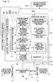
- Fig. 3 is a block diagram showing a schematic configuration of the slip control device 20, etc.
- the inverter device 2 includes: an inverter 17 which converts a direct current from a battery, which is not shown, into a three-phase alternating current; and torque control section 16 which converts the torque command (or torque command value) sent from the VCU 1, into a current command (or current command value) and controls a current output of the inverter 17.
- the torque control section 16 has a control section to perform vector control or the like which achieves efficiency improvement in accordance with a rotation angle of a rotor (not shown) of the motor 3. For the control, a rotation angle detection value of a rotation angle sensor 3a provided to the motor 3 is inputted to the torque control section 16.
- Rotation number conversion section 14a ( Fig. 3 ) is provided which differentiates the rotation angle detection value from the rotation angle sensor 3a and multiplies the differentiated value by a speed reduction rate of the reducer 10 ( Fig. 2 ), thereby to calculate the number of rotations of the drive wheel 7.
- the rotation number conversion section 14a and the rotation angle sensor 3a form rotation detection section 14 configured to detect the number of rotations of the drive wheel 7.
- rotation detection section 14' configured to detect the number of rotations of the drive wheel 7 may be provided, for example, on the wheel bearing 10 ( Fig. 2 ).
- the rotation detection section 15 configured to detect the number of rotations of the driven wheel 6 is provided, for example, on a wheel bearing or the like.
- the rotation detection section 15 is radial type rotation detection section including a rotor 15a and a sensor 15b.
- the rotor 15a includes a plurality of to-be-detected portions 15aa which are arranged around a rotation center L1 at equal pitches.
- the rotor 15a is provided on a rotating ring (not shown) of the wheel bearing and rotates integrally with the driven wheel 6 ( Fig. 3 ).
- the sensor 15b is, for example, an electromagnetic pickup type magnetic sensor, is opposed to the to-be-detected portions 15aa of the rotor 15a across a radial gap, and detects the to-be-detected portions 15aa.
- teeth of a gear type pulse coder formed on an outer peripheral portion of the rotor 15a are used, but the plurality of to-be-detected portions 15aa is not limited thereto.
- a magnetic encoder including to-be-detected portions composed of magnetic poles may be used instead of the teeth of the gear type pulse coder or recesses and projections.
- Axial type rotation detection section 15 may be used in which a detection portion of the sensor 15b is opposed to the to-be-detected portions 15aa across an axial gap.
- the rotation detection section 15 for the driven wheel 6 has been described, in the case where the rotation detection section 14' for the drive wheel 7 is provided, the rotation detection section 14' is the same as the above rotation detection section 15.
- the torque control section 16 is provided in a light current circuit segment composed of a microcomputer or another electronic circuit.
- the slip control section 28 of the slip control device 20 is provided in the light current circuit segment. Control by the slip control devices 20 is performed via the respective torque control sections 16 individually for the right and left drive wheels 7. Each slip control device 20 performs control shown in a flowchart of Fig. 6 described later.
- the inverter device 2 performs various kinds of control for motor driving in a set control repetition cycle.
- One kind of control performed in the control repetition cycle by the inverter device 2 is slip control.
- slip control a process in one cycle from START to RETURN in the flowchart of Fig. 6 described later is repeatedly performed. Specifically, every control repetition cycle, control is performed as to whether a torque command value is decreased or is maintained unchanged.
- the control repetition cycle is not fixed but is variable.
- the slip control device 20 includes a driven wheel rotation number observation section 21, a drive wheel rotation number observation section 23, the slip control section 28, a vehicle speed detection section 29, and a control repetition cycle change section 30.
- the driven wheel rotation number observation section 21 observes a driven wheel number of rotations which is the number of rotations of the driven wheel 6 obtained from the rotation detection section 15, via the VCU 1 constantly, that is, every control repetition cycle described above.
- the observed number of rotations of the driven wheel 6 may be the average of detection values of the numbers of rotations of the driven wheels 6 at both right and left sides, or may be the number of rotations of the driven wheel 6 at the laterally same side as the drive wheel 7 for which the slip control is performed.
- the drive wheel rotation number observation section 23 observes a drive wheel number of rotations which is the number of rotations of the drive wheel 7 obtained from the rotation detection sections 14 or 14'.
- the slip control section 28 performs a series of slip control of decreasing a torque command (value) to the motor 3.
- the slip control section 28 determines whether or not a slip state has occurred, on the basis of the observed drive wheel number of rotations and the observed driven wheel number of rotations. If the slip state has occurred, the series of slip control is performed in the variable control repetition cycle.
- the control repetition cycle change section 30 lengthens the control repetition cycle of the slip control section 28 when a vehicle speed detected by the vehicle speed detection section 29 is in a predetermined low-speed range (e.g., equal to or less than 10 km/h).
- a response cycle Ts (ms) of the rotation speed sensor of the rotation detection section 15 is calculated by the following formula (1).
- Ts 1000 ⁇ 2 ⁇ R / VN
- R is a tire radius (m)
- V is the vehicle speed (m/s)
- N is the number of teeth (the to-be-detected portions) of the above-described rotor.
- the response cycle Ts of the rotation speed sensor becomes slow as the vehicle speed V decreases.
- the response cycle Ts of the rotation speed sensor is too long for the control repetition cycle of the slip control section 28.
- the control repetition cycle change section 30 lengthens the control repetition cycle of the slip control section 28.
- the control repetition cycle is made variable, and the response cycle Ts (ms) of the rotation speed sensor which is calculated by formula (1) is designated as the control repetition cycle T of the slip control section 28. Accordingly, in the low-speed range, the response cycle Ts of the rotation speed sensor is prevented from being too slow for the control repetition cycle T of the slip control section 28.
- the control repetition cycle T of the slip control section 28 can be assuredly caused to substantially coincide with the response cycle of the sensor even when the vehicle speed is any speed in the low-speed range.
- the response cycle Ts of the rotation speed sensor becomes shorter than or equal to 10 ms and thus is prevented from being too slow for the control repetition cycle of 10 ms which is initially set in the slip control section 28.
- the slip control section 28 includes a slip ratio change section 31, a maximum rotation number calculation section 22, a slip state determination section 24, and a slip-time torque cancellation section 26.
- the slip ratio change section 31 sets the slip ratio ⁇ at 0.3 when the vehicle speed exceeds 0 km/h and is equal to or less than 5 km/h, and sets the slip ratio ⁇ at 0.2 when the vehicle speed exceeds 5 km/h and is equal to or less than 10 km/h.
- the maximum rotation number calculation section 22 calculates a drive wheel maximum number of rotations with the above-described slip ratio corresponding to the vehicle speed.
- the drive wheel maximum number of rotations Nmax can be calculated on the basis of a relational expression indicated by the following formula (2).
- N1 is the number of rotations of the driven wheel 6.
- the torque command to the motor 3 is controlled such that the drive wheel maximum number of rotations calculated with the slip ratio ⁇ is not exceeded.
- the drive wheel maximum number of rotations calculated with the slip ratio is small, and thus, due to an error of the rotation detection section 15 ( Fig. 3 ), it may be erroneously determined that a drive wheel number of rotations N2 has fallen within a watch range number of rotations which is set so as to be lower than the drive wheel maximum number of rotations Nmax, or it may be erroneously determined that the drive wheel number of rotations N2 has exceeded the drive wheel maximum number of rotations Nmax.
- the slip ratio is changed from the slip ratio which serves as a reference, in accordance with the vehicle speed in the low-speed range as described above.
- the slip state determination section 24 determines that a slip state has occurred. If the slip state determination section 24 determines that the drive wheel number of rotations N2 has exceeded the drive wheel maximum number of rotations Nmax, it can be inferred that a slip has occurred. At this time, the slip-time torque cancellation section 26 causes a torque command value, which is to be inputted to the torque control section 16, to be zero, or causes a current command, which is to be outputted from the torque control section 16, to be zero.
- the slip control section 28 further includes slip watch range determination section 25 and watch range-time torque reduction section 27. If the slip state determination section 24 determines that the observed drive wheel number of rotations N2 has not exceeded the drive wheel maximum number of rotations Nmax, the slip watch range determination section 25 determines whether or not the drive wheel number of rotations N2 has exceeded a watch range number of rotations Nc which is set so as to be lower than the drive wheel maximum number of rotations Nmax. In other words, through comparison of the drive wheel number of rotations N2 with the watch range number of rotations Nc, the slip watch range determination section 25 determines what extent the drive wheel number of rotations N2 is close to the drive wheel maximum number of rotations Nmax,.
- Fig. 6 is a flowchart showing a control operation of the slip control device. A description will be given also with reference to Fig. 3 .
- this process starts under a condition that the power of the vehicle is turned on (START), and the control repetition cycle change section 30 of the slip control device 20 determines whether or not the vehicle speed detected by the vehicle speed detection section 29 is in the predetermined low-speed range (step S1). If it is determined that the vehicle speed is in the low-speed range (step S1: Yes), the control repetition cycle change section 30 lengthens the control repetition cycle of the slip control section 28 (step S2).
- the driven wheel rotation number observation section 21 monitors, that is, observes, the driven wheel number of rotations N1 obtained from the rotation detection section 15, via the VCU 1 constantly (i.e., every control repetition cycle described above) (step S3).
- the maximum rotation number calculation section 22 calculates the present drive wheel maximum number of rotations Nmax from the obtained present number of rotations N1 of the driven wheel 6 and from the slip ratio ⁇ changed by the slip ratio change section 31, by using formula (2) (step S4). After the calculation of the drive wheel maximum number of rotations Nmax, the drive wheel rotation number observation section 23 observes and obtains the drive wheel number of rotations N2 (step S5). Next, the process proceeds to step S10.
- the drive wheel number of rotations N2 may not be obtained in step S5 but may be obtained during or prior to the calculation of the drive wheel maximum number of rotations Nmax in step S4.
- step S1 If it is determined in step S1 that the vehicle speed is not in the low-speed range (step S1: No), the control repetition cycle of the slip control section 28 is fixed at 10 ms which is initially set (step S6).
- the driven wheel rotation number observation section 21 observes the driven wheel number of rotations N1 (step S7).
- the maximum rotation number calculation section 22 calculates the present drive wheel maximum number of rotations Nmax from the obtained present number of rotations N1 of the driven wheel 6 and the slip ratio ⁇ 0, which serves as a reference, by using formula (2) (step S8), and the drive wheel rotation number observation section 23 observes and obtains the drive wheel number of rotations N2 (step S9). Thereafter, the process proceeds to step S10.
- the drive wheel number of rotations N2 may not be obtained in step S9 but may be obtained during or prior to the calculation of the drive wheel maximum number of rotations Nmax in step S8.
- step S10 the slip state determination section 24 determines whether or not the observed drive wheel number of rotations N2 has exceeded the drive wheel maximum number of rotations Nmax. If it is determined that the observed drive wheel number of rotations N2 has exceeded the drive wheel maximum number of rotations Nmax (step S10: Yes), the slip-time torque cancellation section 26 causes the torque command value, which is to be inputted to the torque control section 16, to be zero, or causes the current command, which is to be outputted from the torque control section 16, to be zero (step S11). In a state where a slip has occurred, the torque command value is maintained at zero. Thereafter, RETURN is made to return the process to START, and the routine in Fig. 6 is repeated from the initial step S 1 again.
- step S10 If it is determined in step S10 that the observed drive wheel number of rotations N2 has not exceeded the drive wheel maximum number of rotations Nmax (step S10: No), the slip watch range determination section 25 determines whether or not the drive wheel number of rotations N2 has fallen within the watch range (step S12). If it is determined that the drive wheel number of rotations N2 has not fallen within the watch range (step S12: No), the present state is a safe state where there is no slip, a process of torque change is not performed (step S13), RETURN is made to return the process to START, and the routine in Fig. 6 is repeated from the initial step S 1 again.
- the watch range-time torque reduction section 27 decreases the torque command value which is to be inputted to the torque control section 16, or decreases the current command which is to be outputted from the torque control section 16 (step S14). Specifically, the difference between the drive wheel number of rotations N2 and the drive wheel maximum number of rotations Nmax is calculated, and sequential deceleration is performed in which the torque command value is decreased by a larger amount as the difference decreases.
- a nonlinear curve A which determines a relationship between the above difference (the horizontal axis) and a ratio of a torque caused to be outputted relative to a torque command inputted from the accelerator (the vertical axis)
- the torque is decreased by a larger amount as the difference decreases (the leftward direction of the horizontal axis in Fig. 7 ). Since an unstable state is enhanced as the drive wheel number of rotations gets close to the maximum number of rotations, the torque is decreased by a larger amount such that the present state quickly returns to a stable state. Accordingly, even if the drive wheel number of rotations exceeds the maximum number of rotations and thus the torque is forcedly made zero, no sudden torque change occurs, and vibration of the vehicle body is reduced, since the torque has been decreased beforehand in the watch range.
- the curve A is assumed to be a curve in which: when the difference is zero, the output ratio of the torque is made zero; as the difference increases, the ratio of the torque caused to be outputted increases but the degree of the increase decreases; and when the difference gets out of the watch range, the output ratio of the torque becomes 100%.
- the curve A has a continuous shape (a shape that allows for differentiation at any point) from the point at which the difference is zero and the torque is zero to the point at which the torque is 100%.
- the slip control section 28 when the vehicle is in a slip state, the slip control section 28 performs the series of slip control of decreasing the torque command to the motor 3, in the variable control repetition cycle. While this slip control is performed, the control repetition cycle change section 30 lengthens the control repetition cycle of the slip control section 28 when the detected vehicle speed is in the predetermined low-speed range (e.g., equal to or less than 10 km/h).
- the predetermined low-speed range e.g., equal to or less than 10 km/h.
- control repetition cycle of the slip control section 28 variable and then lengthening the control repetition cycle in the low-speed range as described above, for example, the control repetition cycle and the response cycle of the sensor for detecting the driven wheel number of rotations can be caused to substantially coincide with each other, so that the response cycle of the sensor can be prevented from being too slow for the control repetition cycle of the slip control section 28. Accordingly, it is possible to prevent an erroneous operation of the slip control section 28 and accurately detect a driven wheel number of rotations, thereby accurately performing the slip control.
- the slip ratio change section 31 changes the slip ratio ⁇ from the slip ratio ⁇ 0, which serves as a reference, in accordance with the vehicle speed as described above, and thus the drive wheel number of rotations can be prevented from erroneously falling within the watch range or exceeding the drive wheel maximum number of rotations due to an error of the rotation detection section 15.
- the watch range-time torque reduction section 27 decreases the torque command value to the motor 3, or decrease the current command which is to be outputted from the torque control section 16.
- the torque of the motor 3 is decreased to some extent beforehand, whereby shock and vibration of the vehicle body in the case that the torque is made zero due to occurrence of a slip are reduced, so that occurrence of an uncomfortable feeling in an occupant can be alleviated.
- each wheel 7 is individually driven by the corresponding motor and is greatly affected by a slip, and therefore the effect by the above slip control is more effectively exerted.
- the response cycle Ts itself of the sensor 15b corresponding to the vehicle speed is designated as the control repetition cycle T of the slip control section 28, but the present invention may include further considerations as long as this basic condition is still met.
- the control repetition cycle T may be uniformly lengthened, or the low-speed range may be divided into a plurality of areas, and the control repetition cycle T may be lengthened by multiplying the initial control repetition cycle T by a multiplying factor that is set for each of the areas obtained by dividing mentioned above.
- the vehicle speed detection section 29 is independently provided, but the present invention is not limited to this example.
- the vehicle speed may be obtained by differentiating a rotation angle of the driven wheel 6 which is detected by the rotation detection section 15.
Landscapes
- Engineering & Computer Science (AREA)
- Transportation (AREA)
- Mechanical Engineering (AREA)
- Power Engineering (AREA)
- Life Sciences & Earth Sciences (AREA)
- Sustainable Development (AREA)
- Sustainable Energy (AREA)
- Chemical & Material Sciences (AREA)
- Combustion & Propulsion (AREA)
- Electric Propulsion And Braking For Vehicles (AREA)
Claims (5)
- Un dispositif de contrôle du glissement (20) pour un véhicule électrique, véhicule qui comprend un moteur électrique (3) configuré pour entrainer en rotation une roue motrice (7), le dispositif de contrôle du glissement (20) réaliantant le contrôle du glissement du véhicule électrique, ce dispositif de contrôle du glissement comprenant :une section d'observation du nombre de rotations de la roue motrice la roue motrice (23) configurée pour observer le nombre de rotations de la roue motrice (7);une section d'observation du nombre de rotations des roues entrainées (21) configurée pour observer le nombre de rotations d'une roue entrainées (6) par l'intermédiaire d'un capteur de vitesse de rotation d'une section de détection (15) de la rotation laquelle présente une durée de cycle de réponse Ts qui dans une plage de basse vitesse prédéterminée varie en fonction de la vitesse du véhicule;une section de contrôle du glissement (28) configurée pour effectuer, dans une durée de cycle de répétition du contrôle Tc, une série de contrôles du glissement qui détermineront si un état de glissement s'est produit ou non, sur la base du nombre de rotations de la roue motrice (7) observé par la section d'observation du nombre de rotations des roues motrices (23) et du nombre de rotations de la roue entraînée (6) observées par la section d'observation du nombre de rotation des roues entraînées (21) et qui diminue une valeur de contrôle de couple du moteur (3) si un état de glissement s'est produit;une section de détection de la vitesse du véhicule (29) configurée pour détecter la vitesse d'un véhicule;une section de changement de cycle de répétition du contrôle (30) configurée pour rendre variable la durée du cycle de répétition Tc de la section de contrôle du glissement (2) puis ensuite prolonger la durée du cycle de répétition Tc de contrôle de la section (28) de façon à ce qu'elle coïncide substantiellement avec la durée du cycle de réponse de la section de détection de la rotation (15), quand la vitesse de véhicule détectée par la section de détection de vitesse de véhicule (29) est dans une gamme prédéterminée de basse vitesse,dans laquelle la section de contrôle du glissement (28) comprend :une section de détermination de la plage de surveillance du glissement (25) configurée pour déterminer si oui ou non le nombre de rotations de la roue motrice (7) a dépassé le nombre de rotations de la plage de surveillance qui est fixé de manière à être inférieur au nombre maximum de rotations de la roue motrice (7), si la section de détermination de l'état du glissement (24) détermine que le nombre de rotations de la roue motrice (7) n'a pas dépassé le nombre maximal de rotations de la roue motrice; etune section de réduction du couple temps-distance de la surveillance(27) configurée pour diminuer la valeur de contrôle du couple pour le moteur (3) si la section de détermination de la plage de surveillance du glissement (25) détermine que le nombre de rotations de la roue motrice (7) a dépassé le nombre de rotations de la plage surveillée.
- Le dispositif de contrôle du glissement d'un véhicule électrique tel que revendiqué dans la réclamation 1, dans lequel
le véhicule électrique comprend une section de détection de la rotation (15) configurée pour détecter le nombre de rotations de la roue entraînée (6), et la section de détection de la rotation (15) comprend: un rotor (15a) comportant une pluralité de parties destinées à être détectées disposées autour d'un centre de rotation à pas égaux, le rotor étant configuré pour tourner intégralement avec la roue entraînée; et un capteur (15b) opposé aux parties destinées à être détectées du rotor (15a) et configuré pour détecter les parties destinées à être détectées, et
lorsque la vitesse du véhicule se trouve dans la plage à basse vitesse prédéterminée, la section de changement de cycle de répétition du contrôle (30) définit le cycle de répétition du contrôle T en fonction de la vitesse du véhicule selon la formule suivante :
- Le dispositif de contrôle du glissement pour le véhicule électrique tel que revendiqué dans la revendication 1 ou 2, dans lequel la section de contrôle du glissement(30) inclut :une section de changement du rapport de glissement (31) configurée pour modifier un rapport du glissement λ dans la vitesse du véhicule détectée par la section de détection de vitesse du véhicule (29) se situe dans la plage prédéterminée à basse vitesse;une section de calcul du nombre de rotation maximum (22) configurée pour calculer un nombre maximum momentané de rotations des roues motrices Nmax en utilisant le rapport du glissement modifié par la section de changement du rapport de glissement et un nombre momentané de rotations N1 de la roue entraînée observée par la section d'observation du nombre de rotation des roues entrainées, selon une relation indiquée par une formule suivante :
 une section de détermination de l'état de glissement (24) configurée pour déterminer qu'un état de glissement s'est produit, lorsque le nombre de rotations de la roue motrice observées par la section d'observation du nombre de rotation des roues motrices a dépassé le nombre maximum de rotations de la roue calculé Nmax.
 - Le dispositif de contrôle du glissement pour le véhicule électrique comme revendiqué dans la revendication 3, dans lequel quand la vitesse de véhicule est dans une gamme de vitesse intermédiaire prédéterminée ou dans une gamme à grande vitesse prédéterminée, la section de calcul de nombre de rotation maximum (22) calcules le nombre maximum momentané de rotations de roue de contrôle Nmax en utilisant un rapport de glissement λ0, qui sert de référence, au lieu du rapport du glissement changé λ.
- Le dispositif de contrôle de glissement pour le véhicule électrique tel que revendiqué dans une quelconque des revendication 1 à 4, dans lequel le moteur (3) forme un dispositif moteur de roue (11).
Applications Claiming Priority (2)
| Application Number | Priority Date | Filing Date | Title |
|---|---|---|---|
| JP2013192602A JP6266280B2 (ja) | 2013-09-18 | 2013-09-18 | 電気自動車のスリップ制御装置 |
| PCT/JP2014/073862 WO2015041108A1 (fr) | 2013-09-18 | 2014-09-10 | Dispositif de régulation du glissement d'un véhicule électrique |
Publications (3)
| Publication Number | Publication Date |
|---|---|
| EP3048002A1 EP3048002A1 (fr) | 2016-07-27 |
| EP3048002A4 EP3048002A4 (fr) | 2017-04-26 |
| EP3048002B1 true EP3048002B1 (fr) | 2021-03-24 |
Family
ID=52688759
Family Applications (1)
| Application Number | Title | Priority Date | Filing Date |
|---|---|---|---|
| EP14845633.8A Not-in-force EP3048002B1 (fr) | 2013-09-18 | 2014-09-10 | Dispositif de régulation du glissement d'un véhicule électrique |
Country Status (5)
| Country | Link |
|---|---|
| US (1) | US10202038B2 (fr) |
| EP (1) | EP3048002B1 (fr) |
| JP (1) | JP6266280B2 (fr) |
| CN (1) | CN105531144B (fr) |
| WO (1) | WO2015041108A1 (fr) |
Families Citing this family (11)
| Publication number | Priority date | Publication date | Assignee | Title |
|---|---|---|---|---|
| CN106004519A (zh) * | 2016-06-21 | 2016-10-12 | 杭州虬龙科技有限公司 | 一种电动车辆的牵引力控制系统 |
| US10065636B2 (en) * | 2016-06-23 | 2018-09-04 | Ford Global Technologies, Llc | Vehicle tire saturation estimator |
| CN106427662A (zh) * | 2016-06-30 | 2017-02-22 | 创驱(上海)新能源科技有限公司 | 一种新能源汽车防抱死控制方法 |
| CN106427663B (zh) * | 2016-07-27 | 2019-01-29 | 北京新能源汽车股份有限公司 | 电动汽车牵引力控制方法和装置 |
| JP2018144576A (ja) * | 2017-03-03 | 2018-09-20 | Ntn株式会社 | 車両制御装置 |
| FR3069223B1 (fr) * | 2017-07-19 | 2020-10-02 | Michelin & Cie | Procede de gestion d'une chaine de traction d'un vehicule automobile |
| CN108437850B (zh) * | 2018-03-20 | 2020-05-05 | 北京经纬恒润科技有限公司 | 一种汽车驱动车轮防滑控制方法和装置 |
| JP7172675B2 (ja) * | 2019-02-04 | 2022-11-16 | トヨタ自動車株式会社 | 電動車両の制御装置 |
| TWI778558B (zh) * | 2021-03-26 | 2022-09-21 | 泓創綠能股份有限公司 | 電動載具的驅動系統及其驅動控制方法 |
| WO2023211339A1 (fr) * | 2022-04-29 | 2023-11-02 | Scania Cv Ab | Dispositif de commande et procédé de prévision de résistance au roulement |
| CN115626067A (zh) * | 2022-10-21 | 2023-01-20 | 华为数字能源技术有限公司 | 一种电机控制模块的控制器、电机的控制方法及相关设备 |
Family Cites Families (13)
| Publication number | Priority date | Publication date | Assignee | Title |
|---|---|---|---|---|
| JP2896383B2 (ja) * | 1990-08-22 | 1999-05-31 | 富士重工業株式会社 | 車両の駆動力制御装置 |
| JP3603018B2 (ja) * | 2000-12-12 | 2004-12-15 | 独立行政法人科学技術振興機構 | 電気自動車の制御装置 |
| JP3699371B2 (ja) * | 2001-07-17 | 2005-09-28 | Ntn株式会社 | インホイールモータ型駆動ユニットおよびハイブリッドシステム |
| US7315804B2 (en) * | 2002-09-04 | 2008-01-01 | Nissan Motor Co., Ltd. | Engineering assist method and system |
| JP3948453B2 (ja) * | 2003-11-18 | 2007-07-25 | 日産自動車株式会社 | 車両の駆動力制御装置 |
| JP4727354B2 (ja) * | 2005-09-07 | 2011-07-20 | 本田技研工業株式会社 | 電動車両の制御装置 |
| JP4358264B2 (ja) * | 2007-08-08 | 2009-11-04 | 株式会社日本自動車部品総合研究所 | ハイブリッド車両 |
| JP4845839B2 (ja) * | 2007-09-20 | 2011-12-28 | 株式会社日立製作所 | 電気駆動車両 |
| EP2527190B1 (fr) * | 2010-01-22 | 2017-06-07 | Hitachi Construction Machinery Co., Ltd. | Véhicule électrique |
| JP5336447B2 (ja) * | 2010-09-02 | 2013-11-06 | 日立建機株式会社 | 電気駆動車両 |
| JP5562277B2 (ja) | 2011-03-07 | 2014-07-30 | Ntn株式会社 | 電気自動車 |
| KR101339233B1 (ko) | 2011-12-01 | 2013-12-09 | 기아자동차 주식회사 | 하이브리드 차량의 엔진 정지상태 판단 시스템 및 방법 |
| JP6223718B2 (ja) | 2013-06-03 | 2017-11-01 | Ntn株式会社 | 電気自動車のスリップ制御装置 |
-
2013
- 2013-09-18 JP JP2013192602A patent/JP6266280B2/ja not_active Expired - Fee Related
-
2014
- 2014-09-10 WO PCT/JP2014/073862 patent/WO2015041108A1/fr not_active Ceased
- 2014-09-10 CN CN201480050720.7A patent/CN105531144B/zh not_active Expired - Fee Related
- 2014-09-10 EP EP14845633.8A patent/EP3048002B1/fr not_active Not-in-force
-
2016
- 2016-03-14 US US15/069,256 patent/US10202038B2/en not_active Expired - Fee Related
Non-Patent Citations (1)
| Title |
|---|
| None * |
Also Published As
| Publication number | Publication date |
|---|---|
| JP6266280B2 (ja) | 2018-01-24 |
| US10202038B2 (en) | 2019-02-12 |
| JP2015061362A (ja) | 2015-03-30 |
| EP3048002A4 (fr) | 2017-04-26 |
| EP3048002A1 (fr) | 2016-07-27 |
| CN105531144A (zh) | 2016-04-27 |
| CN105531144B (zh) | 2018-01-30 |
| US20160193919A1 (en) | 2016-07-07 |
| WO2015041108A1 (fr) | 2015-03-26 |
Similar Documents
| Publication | Publication Date | Title |
|---|---|---|
| EP3048002B1 (fr) | Dispositif de régulation du glissement d'un véhicule électrique | |
| EP3511218B1 (fr) | Système de commande de virage de véhicule | |
| EP2915692A1 (fr) | Dispositif de commande de véhicule | |
| EP3190000B1 (fr) | Dispositif de commande de prévention de dérapage d'un véhicule | |
| EP3020598B1 (fr) | Dispositif de commande de patinage pour véhicule électrique | |
| EP3006259B1 (fr) | Dispositif de commande de glissement destiné à un véhicule électrique | |
| US9475396B2 (en) | Slip control device for electric vehicle | |
| EP3072730A1 (fr) | Dispositif de commande de frein antiblocage | |
| EP3153344B1 (fr) | Dispositif de commande d'entraînement à fonction de contrôle de traction pour véhicule à entraînement indépendant droite-gauche | |
| JP2018157657A (ja) | 車両の制御装置 | |
| EP3088267B1 (fr) | Système d'entraînement de véhicule | |
| CN104527456B (zh) | 动平衡车及其限速控制方法和系统 | |
| JP6050089B2 (ja) | 電気自動車の制御装置およびその電気自動車 | |
| US8725381B2 (en) | Slip detection apparatus and slip detection method | |
| WO2015141519A1 (fr) | Dispositif de contrôle de patinage d'automobile électrique | |
| WO2015002033A1 (fr) | Dispositif de commande de couple d'entraînement | |
| JP5462121B2 (ja) | モータ制御装置 | |
| JP7149713B2 (ja) | スリップ制御装置 | |
| JP4165093B2 (ja) | 車両 |
Legal Events
| Date | Code | Title | Description |
|---|---|---|---|
| PUAI | Public reference made under article 153(3) epc to a published international application that has entered the european phase |
Free format text: ORIGINAL CODE: 0009012 |
|
| 17P | Request for examination filed |
Effective date: 20160318 |
|
| AK | Designated contracting states |
Kind code of ref document: A1 Designated state(s): AL AT BE BG CH CY CZ DE DK EE ES FI FR GB GR HR HU IE IS IT LI LT LU LV MC MK MT NL NO PL PT RO RS SE SI SK SM TR |
|
| AX | Request for extension of the european patent |
Extension state: BA ME |
|
| DAX | Request for extension of the european patent (deleted) | ||
| A4 | Supplementary search report drawn up and despatched |
Effective date: 20170324 |
|
| RIC1 | Information provided on ipc code assigned before grant |
Ipc: B60L 3/10 20060101ALI20170320BHEP Ipc: B60L 15/20 20060101AFI20170320BHEP |
|
| GRAP | Despatch of communication of intention to grant a patent |
Free format text: ORIGINAL CODE: EPIDOSNIGR1 |
|
| STAA | Information on the status of an ep patent application or granted ep patent |
Free format text: STATUS: GRANT OF PATENT IS INTENDED |
|
| INTG | Intention to grant announced |
Effective date: 20201106 |
|
| GRAS | Grant fee paid |
Free format text: ORIGINAL CODE: EPIDOSNIGR3 |
|
| GRAA | (expected) grant |
Free format text: ORIGINAL CODE: 0009210 |
|
| STAA | Information on the status of an ep patent application or granted ep patent |
Free format text: STATUS: THE PATENT HAS BEEN GRANTED |
|
| AK | Designated contracting states |
Kind code of ref document: B1 Designated state(s): AL AT BE BG CH CY CZ DE DK EE ES FI FR GB GR HR HU IE IS IT LI LT LU LV MC MK MT NL NO PL PT RO RS SE SI SK SM TR |
|
| REG | Reference to a national code |
Ref country code: GB Ref legal event code: FG4D |
|
| REG | Reference to a national code |
Ref country code: CH Ref legal event code: EP |
|
| REG | Reference to a national code |
Ref country code: IE Ref legal event code: FG4D |
|
| REG | Reference to a national code |
Ref country code: AT Ref legal event code: REF Ref document number: 1374150 Country of ref document: AT Kind code of ref document: T Effective date: 20210415 Ref country code: DE Ref legal event code: R096 Ref document number: 602014076016 Country of ref document: DE |
|
| REG | Reference to a national code |
Ref country code: LT Ref legal event code: MG9D |
|
| PG25 | Lapsed in a contracting state [announced via postgrant information from national office to epo] |
Ref country code: FI Free format text: LAPSE BECAUSE OF FAILURE TO SUBMIT A TRANSLATION OF THE DESCRIPTION OR TO PAY THE FEE WITHIN THE PRESCRIBED TIME-LIMIT Effective date: 20210324 Ref country code: HR Free format text: LAPSE BECAUSE OF FAILURE TO SUBMIT A TRANSLATION OF THE DESCRIPTION OR TO PAY THE FEE WITHIN THE PRESCRIBED TIME-LIMIT Effective date: 20210324 Ref country code: GR Free format text: LAPSE BECAUSE OF FAILURE TO SUBMIT A TRANSLATION OF THE DESCRIPTION OR TO PAY THE FEE WITHIN THE PRESCRIBED TIME-LIMIT Effective date: 20210625 Ref country code: BG Free format text: LAPSE BECAUSE OF FAILURE TO SUBMIT A TRANSLATION OF THE DESCRIPTION OR TO PAY THE FEE WITHIN THE PRESCRIBED TIME-LIMIT Effective date: 20210624 Ref country code: NO Free format text: LAPSE BECAUSE OF FAILURE TO SUBMIT A TRANSLATION OF THE DESCRIPTION OR TO PAY THE FEE WITHIN THE PRESCRIBED TIME-LIMIT Effective date: 20210624 |
|
| PG25 | Lapsed in a contracting state [announced via postgrant information from national office to epo] |
Ref country code: RS Free format text: LAPSE BECAUSE OF FAILURE TO SUBMIT A TRANSLATION OF THE DESCRIPTION OR TO PAY THE FEE WITHIN THE PRESCRIBED TIME-LIMIT Effective date: 20210324 Ref country code: LV Free format text: LAPSE BECAUSE OF FAILURE TO SUBMIT A TRANSLATION OF THE DESCRIPTION OR TO PAY THE FEE WITHIN THE PRESCRIBED TIME-LIMIT Effective date: 20210324 Ref country code: SE Free format text: LAPSE BECAUSE OF FAILURE TO SUBMIT A TRANSLATION OF THE DESCRIPTION OR TO PAY THE FEE WITHIN THE PRESCRIBED TIME-LIMIT Effective date: 20210324 |
|
| REG | Reference to a national code |
Ref country code: NL Ref legal event code: MP Effective date: 20210324 |
|
| REG | Reference to a national code |
Ref country code: AT Ref legal event code: MK05 Ref document number: 1374150 Country of ref document: AT Kind code of ref document: T Effective date: 20210324 |
|
| PG25 | Lapsed in a contracting state [announced via postgrant information from national office to epo] |
Ref country code: NL Free format text: LAPSE BECAUSE OF FAILURE TO SUBMIT A TRANSLATION OF THE DESCRIPTION OR TO PAY THE FEE WITHIN THE PRESCRIBED TIME-LIMIT Effective date: 20210324 |
|
| PG25 | Lapsed in a contracting state [announced via postgrant information from national office to epo] |
Ref country code: SM Free format text: LAPSE BECAUSE OF FAILURE TO SUBMIT A TRANSLATION OF THE DESCRIPTION OR TO PAY THE FEE WITHIN THE PRESCRIBED TIME-LIMIT Effective date: 20210324 Ref country code: EE Free format text: LAPSE BECAUSE OF FAILURE TO SUBMIT A TRANSLATION OF THE DESCRIPTION OR TO PAY THE FEE WITHIN THE PRESCRIBED TIME-LIMIT Effective date: 20210324 Ref country code: CZ Free format text: LAPSE BECAUSE OF FAILURE TO SUBMIT A TRANSLATION OF THE DESCRIPTION OR TO PAY THE FEE WITHIN THE PRESCRIBED TIME-LIMIT Effective date: 20210324 Ref country code: LT Free format text: LAPSE BECAUSE OF FAILURE TO SUBMIT A TRANSLATION OF THE DESCRIPTION OR TO PAY THE FEE WITHIN THE PRESCRIBED TIME-LIMIT Effective date: 20210324 Ref country code: AT Free format text: LAPSE BECAUSE OF FAILURE TO SUBMIT A TRANSLATION OF THE DESCRIPTION OR TO PAY THE FEE WITHIN THE PRESCRIBED TIME-LIMIT Effective date: 20210324 |
|
| PGFP | Annual fee paid to national office [announced via postgrant information from national office to epo] |
Ref country code: FR Payment date: 20210709 Year of fee payment: 8 |
|
| PG25 | Lapsed in a contracting state [announced via postgrant information from national office to epo] |
Ref country code: PT Free format text: LAPSE BECAUSE OF FAILURE TO SUBMIT A TRANSLATION OF THE DESCRIPTION OR TO PAY THE FEE WITHIN THE PRESCRIBED TIME-LIMIT Effective date: 20210726 Ref country code: PL Free format text: LAPSE BECAUSE OF FAILURE TO SUBMIT A TRANSLATION OF THE DESCRIPTION OR TO PAY THE FEE WITHIN THE PRESCRIBED TIME-LIMIT Effective date: 20210324 Ref country code: ES Free format text: LAPSE BECAUSE OF FAILURE TO SUBMIT A TRANSLATION OF THE DESCRIPTION OR TO PAY THE FEE WITHIN THE PRESCRIBED TIME-LIMIT Effective date: 20210324 Ref country code: SK Free format text: LAPSE BECAUSE OF FAILURE TO SUBMIT A TRANSLATION OF THE DESCRIPTION OR TO PAY THE FEE WITHIN THE PRESCRIBED TIME-LIMIT Effective date: 20210324 Ref country code: RO Free format text: LAPSE BECAUSE OF FAILURE TO SUBMIT A TRANSLATION OF THE DESCRIPTION OR TO PAY THE FEE WITHIN THE PRESCRIBED TIME-LIMIT Effective date: 20210324 Ref country code: IS Free format text: LAPSE BECAUSE OF FAILURE TO SUBMIT A TRANSLATION OF THE DESCRIPTION OR TO PAY THE FEE WITHIN THE PRESCRIBED TIME-LIMIT Effective date: 20210724 |
|
| PGFP | Annual fee paid to national office [announced via postgrant information from national office to epo] |
Ref country code: DE Payment date: 20210830 Year of fee payment: 8 |
|
| REG | Reference to a national code |
Ref country code: DE Ref legal event code: R097 Ref document number: 602014076016 Country of ref document: DE |
|
| PG25 | Lapsed in a contracting state [announced via postgrant information from national office to epo] |
Ref country code: DK Free format text: LAPSE BECAUSE OF FAILURE TO SUBMIT A TRANSLATION OF THE DESCRIPTION OR TO PAY THE FEE WITHIN THE PRESCRIBED TIME-LIMIT Effective date: 20210324 Ref country code: AL Free format text: LAPSE BECAUSE OF FAILURE TO SUBMIT A TRANSLATION OF THE DESCRIPTION OR TO PAY THE FEE WITHIN THE PRESCRIBED TIME-LIMIT Effective date: 20210324 |
|
| PLBE | No opposition filed within time limit |
Free format text: ORIGINAL CODE: 0009261 |
|
| STAA | Information on the status of an ep patent application or granted ep patent |
Free format text: STATUS: NO OPPOSITION FILED WITHIN TIME LIMIT |
|
| PG25 | Lapsed in a contracting state [announced via postgrant information from national office to epo] |
Ref country code: SI Free format text: LAPSE BECAUSE OF FAILURE TO SUBMIT A TRANSLATION OF THE DESCRIPTION OR TO PAY THE FEE WITHIN THE PRESCRIBED TIME-LIMIT Effective date: 20210324 |
|
| 26N | No opposition filed |
Effective date: 20220104 |
|
| REG | Reference to a national code |
Ref country code: CH Ref legal event code: PL |
|
| REG | Reference to a national code |
Ref country code: BE Ref legal event code: MM Effective date: 20210930 |
|
| GBPC | Gb: european patent ceased through non-payment of renewal fee |
Effective date: 20210910 |
|
| PG25 | Lapsed in a contracting state [announced via postgrant information from national office to epo] |
Ref country code: IS Free format text: LAPSE BECAUSE OF FAILURE TO SUBMIT A TRANSLATION OF THE DESCRIPTION OR TO PAY THE FEE WITHIN THE PRESCRIBED TIME-LIMIT Effective date: 20210724 Ref country code: MC Free format text: LAPSE BECAUSE OF FAILURE TO SUBMIT A TRANSLATION OF THE DESCRIPTION OR TO PAY THE FEE WITHIN THE PRESCRIBED TIME-LIMIT Effective date: 20210324 |
|
| PG25 | Lapsed in a contracting state [announced via postgrant information from national office to epo] |
Ref country code: LU Free format text: LAPSE BECAUSE OF NON-PAYMENT OF DUE FEES Effective date: 20210910 Ref country code: IE Free format text: LAPSE BECAUSE OF NON-PAYMENT OF DUE FEES Effective date: 20210910 Ref country code: GB Free format text: LAPSE BECAUSE OF NON-PAYMENT OF DUE FEES Effective date: 20210910 Ref country code: BE Free format text: LAPSE BECAUSE OF NON-PAYMENT OF DUE FEES Effective date: 20210930 |
|
| PG25 | Lapsed in a contracting state [announced via postgrant information from national office to epo] |
Ref country code: LI Free format text: LAPSE BECAUSE OF NON-PAYMENT OF DUE FEES Effective date: 20210930 Ref country code: CH Free format text: LAPSE BECAUSE OF NON-PAYMENT OF DUE FEES Effective date: 20210930 |
|
| PG25 | Lapsed in a contracting state [announced via postgrant information from national office to epo] |
Ref country code: IT Free format text: LAPSE BECAUSE OF FAILURE TO SUBMIT A TRANSLATION OF THE DESCRIPTION OR TO PAY THE FEE WITHIN THE PRESCRIBED TIME-LIMIT Effective date: 20210324 |
|
| REG | Reference to a national code |
Ref country code: DE Ref legal event code: R119 Ref document number: 602014076016 Country of ref document: DE |
|
| PG25 | Lapsed in a contracting state [announced via postgrant information from national office to epo] |
Ref country code: HU Free format text: LAPSE BECAUSE OF FAILURE TO SUBMIT A TRANSLATION OF THE DESCRIPTION OR TO PAY THE FEE WITHIN THE PRESCRIBED TIME-LIMIT; INVALID AB INITIO Effective date: 20140910 |
|
| PG25 | Lapsed in a contracting state [announced via postgrant information from national office to epo] |
Ref country code: CY Free format text: LAPSE BECAUSE OF FAILURE TO SUBMIT A TRANSLATION OF THE DESCRIPTION OR TO PAY THE FEE WITHIN THE PRESCRIBED TIME-LIMIT Effective date: 20210324 |
|
| PG25 | Lapsed in a contracting state [announced via postgrant information from national office to epo] |
Ref country code: FR Free format text: LAPSE BECAUSE OF NON-PAYMENT OF DUE FEES Effective date: 20220930 Ref country code: DE Free format text: LAPSE BECAUSE OF NON-PAYMENT OF DUE FEES Effective date: 20230401 |
|
| PG25 | Lapsed in a contracting state [announced via postgrant information from national office to epo] |
Ref country code: MK Free format text: LAPSE BECAUSE OF FAILURE TO SUBMIT A TRANSLATION OF THE DESCRIPTION OR TO PAY THE FEE WITHIN THE PRESCRIBED TIME-LIMIT Effective date: 20210324 |
|
| PG25 | Lapsed in a contracting state [announced via postgrant information from national office to epo] |
Ref country code: TR Free format text: LAPSE BECAUSE OF FAILURE TO SUBMIT A TRANSLATION OF THE DESCRIPTION OR TO PAY THE FEE WITHIN THE PRESCRIBED TIME-LIMIT Effective date: 20210324 |
|
| PG25 | Lapsed in a contracting state [announced via postgrant information from national office to epo] |
Ref country code: MT Free format text: LAPSE BECAUSE OF FAILURE TO SUBMIT A TRANSLATION OF THE DESCRIPTION OR TO PAY THE FEE WITHIN THE PRESCRIBED TIME-LIMIT Effective date: 20210324 |