EP3048220B1 - Vorrichtung zur reinigung von bodenflächen - Google Patents
Vorrichtung zur reinigung von bodenflächen Download PDFInfo
- Publication number
- EP3048220B1 EP3048220B1 EP13893770.1A EP13893770A EP3048220B1 EP 3048220 B1 EP3048220 B1 EP 3048220B1 EP 13893770 A EP13893770 A EP 13893770A EP 3048220 B1 EP3048220 B1 EP 3048220B1
- Authority
- EP
- European Patent Office
- Prior art keywords
- rollers
- floor cleaner
- casing
- cleaner
- floor
- Prior art date
- Legal status (The legal status is an assumption and is not a legal conclusion. Google has not performed a legal analysis and makes no representation as to the accuracy of the status listed.)
- Active
Links
Images




Classifications
-
- G—PHYSICS
- G21—NUCLEAR PHYSICS; NUCLEAR ENGINEERING
- G21C—NUCLEAR REACTORS
- G21C19/00—Arrangements for treating, for handling, or for facilitating the handling of, fuel or other materials which are used within the reactor, e.g. within its pressure vessel
- G21C19/20—Arrangements for introducing objects into the pressure vessel; Arrangements for handling objects within the pressure vessel; Arrangements for removing objects from the pressure vessel
- G21C19/207—Assembling, maintenance or repair of reactor components
-
- B—PERFORMING OPERATIONS; TRANSPORTING
- B08—CLEANING
- B08B—CLEANING IN GENERAL; PREVENTION OF FOULING IN GENERAL
- B08B1/00—Cleaning by methods involving the use of tools
- B08B1/30—Cleaning by methods involving the use of tools by movement of cleaning members over a surface
- B08B1/32—Cleaning by methods involving the use of tools by movement of cleaning members over a surface using rotary cleaning members
- B08B1/34—Cleaning by methods involving the use of tools by movement of cleaning members over a surface using rotary cleaning members rotating about an axis parallel to the surface
-
- B—PERFORMING OPERATIONS; TRANSPORTING
- B08—CLEANING
- B08B—CLEANING IN GENERAL; PREVENTION OF FOULING IN GENERAL
- B08B9/00—Cleaning hollow articles by methods or apparatus specially adapted thereto
- B08B9/08—Cleaning containers, e.g. tanks
- B08B9/087—Cleaning containers, e.g. tanks by methods involving the use of tools, e.g. brushes, scrapers
-
- E—FIXED CONSTRUCTIONS
- E04—BUILDING
- E04H—BUILDINGS OR LIKE STRUCTURES FOR PARTICULAR PURPOSES; SWIMMING OR SPLASH BATHS OR POOLS; MASTS; FENCING; TENTS OR CANOPIES, IN GENERAL
- E04H4/00—Swimming or splash baths or pools
- E04H4/14—Parts, details or accessories not otherwise provided for
- E04H4/16—Parts, details or accessories not otherwise provided for specially adapted for cleaning
- E04H4/1654—Self-propelled cleaners
-
- G—PHYSICS
- G21—NUCLEAR PHYSICS; NUCLEAR ENGINEERING
- G21C—NUCLEAR REACTORS
- G21C17/00—Monitoring; Testing ; Maintaining
- G21C17/003—Remote inspection of vessels, e.g. pressure vessels
- G21C17/013—Inspection vehicles
-
- G—PHYSICS
- G21—NUCLEAR PHYSICS; NUCLEAR ENGINEERING
- G21C—NUCLEAR REACTORS
- G21C19/00—Arrangements for treating, for handling, or for facilitating the handling of, fuel or other materials which are used within the reactor, e.g. within its pressure vessel
- G21C19/02—Details of handling arrangements
- G21C19/06—Magazines for holding fuel elements or control elements
- G21C19/07—Storage racks; Storage pools
-
- G—PHYSICS
- G21—NUCLEAR PHYSICS; NUCLEAR ENGINEERING
- G21F—PROTECTION AGAINST X-RADIATION, GAMMA RADIATION, CORPUSCULAR RADIATION OR PARTICLE BOMBARDMENT; TREATING RADIOACTIVELY CONTAMINATED MATERIAL; DECONTAMINATION ARRANGEMENTS THEREFOR
- G21F9/00—Treating radioactively contaminated material; Decontamination arrangements therefor
-
- G—PHYSICS
- G21—NUCLEAR PHYSICS; NUCLEAR ENGINEERING
- G21F—PROTECTION AGAINST X-RADIATION, GAMMA RADIATION, CORPUSCULAR RADIATION OR PARTICLE BOMBARDMENT; TREATING RADIOACTIVELY CONTAMINATED MATERIAL; DECONTAMINATION ARRANGEMENTS THEREFOR
- G21F9/00—Treating radioactively contaminated material; Decontamination arrangements therefor
- G21F9/001—Decontamination of contaminated objects, apparatus, clothes, food; Preventing contamination thereof
- G21F9/002—Decontamination of the surface of objects with chemical or electrochemical processes
- G21F9/004—Decontamination of the surface of objects with chemical or electrochemical processes of metallic surfaces
-
- E—FIXED CONSTRUCTIONS
- E04—BUILDING
- E04H—BUILDINGS OR LIKE STRUCTURES FOR PARTICULAR PURPOSES; SWIMMING OR SPLASH BATHS OR POOLS; MASTS; FENCING; TENTS OR CANOPIES, IN GENERAL
- E04H4/00—Swimming or splash baths or pools
- E04H4/14—Parts, details or accessories not otherwise provided for
- E04H4/16—Parts, details or accessories not otherwise provided for specially adapted for cleaning
- E04H4/1654—Self-propelled cleaners
- E04H4/1663—Self-propelled cleaners the propulsion resulting from an intermittent interruption of the waterflow through the cleaner
-
- Y—GENERAL TAGGING OF NEW TECHNOLOGICAL DEVELOPMENTS; GENERAL TAGGING OF CROSS-SECTIONAL TECHNOLOGIES SPANNING OVER SEVERAL SECTIONS OF THE IPC; TECHNICAL SUBJECTS COVERED BY FORMER USPC CROSS-REFERENCE ART COLLECTIONS [XRACs] AND DIGESTS
- Y02—TECHNOLOGIES OR APPLICATIONS FOR MITIGATION OR ADAPTATION AGAINST CLIMATE CHANGE
- Y02E—REDUCTION OF GREENHOUSE GAS [GHG] EMISSIONS, RELATED TO ENERGY GENERATION, TRANSMISSION OR DISTRIBUTION
- Y02E30/00—Energy generation of nuclear origin
- Y02E30/30—Nuclear fission reactors
Definitions
- This invention refers to a floor cleaner specially designed to be used in critical areas with difficult accessibility or restricted access, such as the pools used for housing a reactor vessel at a nuclear power station, in which human presence must be avoided as far as possible or only be for the shortest possible time, when this is absolutely necessary.
- the floor cleaner comprises:
- the pools in which the reactor of a nuclear power station is housed are made up of a compartment which may be in a regular or irregular shape and have dimensions that can range from one or two dozen metres on the smaller horizontal side to several dozen metres on the larger side, with a height of several metres, able to temporarily house a large number of the components of the reactor in the dismantling stage.
- a device is thus required for cleaning the floors of the pools in which reactors of nuclear power stations are housed which is able to clean narrow spaces, to the maximum width of the apparatus and which is able to get over any small obstacles which it might come up against.
- EP 1472425 describes an independent floor cleaner for pools which comprises a set of support wheels and is provided with filtration and pumping means. It does not have means of controlling the movement.
- EP 1002173 discloses a floor cleaner with movement induced by a suction flow from an exterior pump; like the previous one this does not have any means for controlling its movement.
- WO2013/030005 teaches a device for submersibly cleaning surfaces inside a nuclear reactor with two cleaning rollers.
- a robot device known on the market as "ZODIAC Sweepy M3”, comprises a pair of lateral drive chains driven by motors and also comprises a motor for pumping water through a filter.
- the cleaning width is nevertheless interior, between the drive chains, for which reason it is far from the outer edges. Furthermore, since this is conceived for cleaning swimming pools, it is not designed to get over obstacles.
- the "WEDA N600” device is also a compact device able to be handled in remote control or in automatic mode, which has, like the previous one, a pair of drive chains, in this case with front and rear brushes of a width approximately equal to that of the body of the device and in which the extraction system installed in the apparatus itself expels the water through filter bags.
- the "ATOX underwater bottom cleaner” device has a structure similar to the previous ones, in that this is provided with lateral drive chains, with a filtration body operated with an exterior pump.
- This device is its weight, apart from the difficulties of cleaning the side zones, for the reasons given above.
- any of these can be held up by a small obstacle, such as a bolt head two or three centimetres high, when said obstacle is not directly confronted by one of the drive chains.
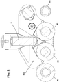
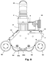
- the invention being proposed consists of a floor cleaner which comprises a casing or housing carrying the other items, which forms a suction bell. This is moved by drive wheels or chains (belts); it is preferable for the movement to take place by means of belts, as the possibility of the device being held up on an obstacle, such as a bolt head, is lower if this option is used. It is driven by means of independent motors, with variable speed and rotation direction, meaning that, depending on the rotation direction of the motors, the cleaner can move forward when both belts rotate at the same speed in one direction, move in reverse when they rotate inversely in respect of the above or rotate on its own axis if the belt movements are mutually inverse or with displacement when the speeds of the belts are different.
- interior rollers and exterior rollers For proper cleaning of the floor, there are interior rollers and exterior rollers.
- two interior rollers are used, with the suction bell between them, and two rollers (two geometrical axles carrying the rollers).
- the interior set of these rollers has a smaller size than the width of the cleaner, insofar as these are driven from at least one of its sides.
- the outer rollers are thus divided into two portions, and driven from the centre, so that the free end of each side reaches the width required; in particular the length of the rollers is greater than the width of the cleaner casing.
- the rollers are made up of a core and a sheath. It has been found that an ideal sheath for proper cleaning is made up of rubber strips, arranged radially (in a transversal direction to the movement). Hence, at least some of the strips will have to be positioned radially in respect of the roller axis. These transversal strips may be joined to strips arranged on a plane perpendicular to the axle of the roller without impairing their operation.
- the exterior rollers (and preferably also the interior ones) rotate towards the interior of the suction bell (they drag the dirt along the floor towards the interior of the suction bell).
- the movement of the rollers and especially that of the interior rollers in respect of the exterior ones may be mutually independent (with different motors and mechanical systems) or can be synchronised with each other (driven by a single motor) but is always independent from the displacement movement of the cleaner, driven by two independent motors.
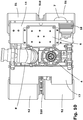
- motors and mechanical transmission assemblies For the movement of the rollers and the drive belts, there are respectively motors and mechanical transmission assemblies, each formed of a plurality of pinions engaging each other.
- the exterior rollers are driven from the central part; this central drive is made up of an arm or support which houses a mechanism, and sustains the corresponding parts of the lateral rollers projecting outward.
- the sheath of the interior rollers must therefore be continuous on the longitudinal plane on which the mechanism for driving the exterior rollers is located, especially the front rollers.
- the front arm has been designed for the front arm to be hinged, and to be subject to an elastic retaining tension, so that the elevation tension is lower than the cleaner's effective weight in the water and so that when an obstacle is reached said arm rises over the obstacle and the cleaner continues its displacement and after the obstacle is reached by the drive belts, these are indeed able to get over this with no further problems, the arm returning to the normal working position when the elastic tension caused on reaching the obstacle has been released.
- At least one of the rollers normally the front interior roller, has been provided with a set of wheels joined to its axle, so that when the cleaner comes up against an obstacle, these wheels continue to pull.
- the wheels have a smaller diameter than that of the corresponding brush, so that they will not be in contact with the floor unless an obstacle with sufficient height is found. This guarantees that the cleaning is correct in routes with no obstacles.
- said rollers are also designed to be fitted with wheels.
- said wheels are designed to be freely rotating, constituting only a support which does not force any inverse movement because of the movement of the corresponding brush.
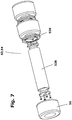
- the suction head forming the external casing or housing comprises an upper suction mouth which is connected to a suction pump; the element for connection to the pump is designed to be freely rotating at both mouths and obliquely at 45° in its central zone allowing positioning with no restriction both from the upper end and from any lateral position.
- the casing is made up of lateral elements and an upper cover closed at the front and rear by the relevant rollers
- each of the lateral elements is formed of separate parallel plates which define a chamber housing mechanical transmission assemblies.
- the casing comprises a turbine which takes the water from the inside of the bell, and ejects this outwards in the opposite direction, upwards when the cleaner is on the floor.
- the cleaner is designed to have lighting means, at least in the forward motion direction, but possibly also for reverse movement.
- the cleaner comprises an electronic control system.
- the electronic control system determines the actions of speeds and movement directions of each of the motors for driving the displacement or movement of the rollers and the turbine, of the lighting and picture-taking elements, or indicates any fault which might arise in the device.
- the electronic system comprises a sealed connection box for connecting the electric supply and control cables of the device.
- the control body is preferably formed of at least two elements, one of these constituting the actual electronics of the device, and the control system is normally placed in a remote unit, this remote unit normally being a computer. It could possibly have an intermediate unit, for example in a float which minimises the requirements of control cable sections, when the distances are excessively long, and which allows control by means of wireless means, where applicable.
- the invention being proposed consists, as stated in the heading, of a floor cleaner, governed by remote control, which is suitable for use in cleaning the floors and walls of the pools housing the vessel of nuclear power stations, which comprises:
- the drive and cleaning body has a maximum width of roughly 32 cm and a length of roughly 41 cm, with a height up to the suction mouth under 30 cm, which allows great manoeuvring capacity and can reach recesses which would be impossible for other devices due to their dimensions and structure.
Landscapes
- Engineering & Computer Science (AREA)
- Physics & Mathematics (AREA)
- General Engineering & Computer Science (AREA)
- High Energy & Nuclear Physics (AREA)
- Plasma & Fusion (AREA)
- Architecture (AREA)
- Mechanical Engineering (AREA)
- Structural Engineering (AREA)
- Civil Engineering (AREA)
- Chemical & Material Sciences (AREA)
- Food Science & Technology (AREA)
- Life Sciences & Earth Sciences (AREA)
- General Chemical & Material Sciences (AREA)
- Electrochemistry (AREA)
- Chemical Kinetics & Catalysis (AREA)
- Cleaning In General (AREA)
- Nozzles For Electric Vacuum Cleaners (AREA)
- Electric Suction Cleaners (AREA)
Claims (22)
- Bodenreiniger, der mit einem äußeren Gehäuse (1) bereitgestellt ist, das eine Saugglocke mit einer oberen Saugöffnung (2) bildet, wobei dieses Gehäuse (1) eine Vorderkante, eine Hinterkante und seitliche Elemente (11) umfasst und mit Zugeinrichtungen (55, 551) bereitgestellt ist, die an einem der seitlichen Elemente eingepasst sind, die mit unabhängigen Antriebsmotoren und entsprechenden Übertragungsmechanismen auf jeder Seite ausgestattet sind, wobei der Bodenreiniger ferner mit Reinigungswalzen (51, 52, 53, 54) bereitgestellt ist, und dadurch gekennzeichnet, dass er Folgendes umfasst:• Anordnungen von inneren Reinigungswalzen (53, 54), die innerhalb des Gehäuses (1) nahe der Mitte des Gehäuses angeordnet sind, deren Breite etwa gleich dem Abstand zwischen den Seitenelementen (11) des Gehäuses (1) ist;• Anordnungen von äußeren Reinigungswalzen (51, 52), die in einem Bereich nahe der Vorderkante und nahe der Hinterkante des Gehäuses (1) des Reinigers angeordnet sind, deren Gesamtbreite geringfügig größer als die Breite des Gehäuses ist.
- Bodenreiniger nach einem der vorhergehenden Ansprüche, dadurch gekennzeichnet, dass die Saugöffnung (2) mit einem Drehelement (25) bereitgestellt ist, das mit dem Gehäuse verbunden ist.
- Bodenreiniger nach einem der Ansprüche 1 bis 2, dadurch gekennzeichnet, dass die Saugöffnung (2) mit einer externen Saugquelle verbunden ist.
- Bodenreiniger nach Anspruch 3, dadurch gekennzeichnet, dass die Saugöffnung auch einen sich um 45° drehenden Körper (21) mit einem unteren Element (24) und einem oberen Element (23) umfasst, die wiederum mit einer Drehöffnung (22) ausgestattet sind.
- Bodenreiniger nach einem der Ansprüche 1 bis 4, dadurch gekennzeichnet, dass das Gehäuse (1) eine interne Saugturbine (8) umfasst.
- Bodenreiniger nach einem der Ansprüche 1 bis 4, dadurch gekennzeichnet, dass das Gehäuse (1) auch einen Filter umfasst, der direkt mit dem Sauger (2) verbunden ist.
- Bodenreiniger nach einem der Ansprüche 1 bis 6, dadurch gekennzeichnet, dass die Bewegung der äußeren Reinigungswalzen (51, 52) unabhängig von derjenigen der inneren Reinigungswalzen (53, 54) sowie der Antriebsmotoren und relevanten Getriebemechanismen ist.
- Bodenreiniger nach einem der Ansprüche 1 bis 6, dadurch gekennzeichnet, dass die Bewegung der äußeren Reinigungswalzen (51) mit derjenigen der inneren Reinigungswalzen (53, 54) synchronisiert ist, wobei alle durch einen einzigen Antriebsmotor und entsprechende Getriebemechanismen bewegt werden.
- Bodenreiniger nach einem der Ansprüche 1 bis 8, dadurch gekennzeichnet, dass die inneren Walzen (53, 54) durchgehend sind, wobei ein Kern aus einem einzigen starren Körper gebildet ist, und dadurch dass der Antriebsmechanismus an mindestens einer der Kanten angeordnet ist.
- Bodenreiniger nach einem der Ansprüche 1 bis 9, dadurch gekennzeichnet, dass die äußeren Walzen (51, 52) in zwei Abschnitte mit einem zentralen Antriebsmechanismus unterteilt sind, welcher die einzige Stütze für jeden der Abschnitte bildet.
- Bodenreiniger nach Anspruch 10, dadurch gekennzeichnet, dass die inneren Walzen mit einem oder mehr Stützrädern (539) bereitgestellt sind, die sich zusammen mit der Walze bewegen, auf der diese angeordnet sind.
- Bodenreiniger nach Anspruch 10, dadurch gekennzeichnet, dass die inneren Walzen mit einem oder mehreren Stützrädern (539) bereitgestellt sind, die sich frei in Bezug auf die Walze bewegen, auf der diese angeordnet sind.
- Bodenreiniger nach einem der Ansprüche 11 und 12, dadurch gekennzeichnet, dass die Stützräder der inneren Walzen nicht mit dem Mechanismus zum Antreiben der äußeren Walzen ausgerichtet sind.
- Bodenreiniger nach einem der Ansprüche 1 bis 13, dadurch gekennzeichnet, dass die Walzen aus einem Kern (518, 528, 538) bestehen, der mit einem Band (56) aus einem elastischen Werkstoff bedeckt ist, das die Reinigungsbürste bildet, die mindestens eine Reihe von Laschen oder Lamellen (561) umfasst, die in einer radialen Position auf ihrer Außenfläche angeordnet sind.
- Bodenreiniger nach einem der Ansprüche 1 bis 13, dadurch gekennzeichnet, dass die Walzen, die in dem Bereich nahe der Vorderkante angeordnet sind, und/oder die Walzen, die in dem Bereich nahe der Hinterkante angeordnet sind, an einem Arm (520) angebracht sind, der in Bezug auf das Gehäuse (1) beweglich ist, und dadurch, dass der Arm mit elastischen Mitteln bereitgestellt ist, welche diese in ihre Arbeitsposition zurückführen, wenn diese Position durch das Vorhandensein eines Hindernisses abgeändert wurde.
- Bodenreiniger nach einem der Ansprüche 1 bis 15, dadurch gekennzeichnet, dass er auch eine Turbine (4) zum Anhaften an dem Boden umfasst, welche das Wasser von außerhalb der Glocke aufnimmt und dieses senkrecht zu der Stützfläche ausstößt.
- Bodenreiniger nach einem der Ansprüche 1 bis 16, dadurch gekennzeichnet, dass er mindestens einen Beleuchtungsscheinwerfer umfasst.
- Bodenreiniger nach einem der Ansprüche 1 bis 17, dadurch gekennzeichnet, dass er auch eine Kamera zum Machen von Aufnahmen umfasst.
- Bodenreiniger nach einem der Ansprüche 1 bis 18, dadurch gekennzeichnet, dass er auch ein elektronisches System zur Steuerung und Lenkung mit abgedichteten Anschlüssen umfasst.
- Bodenreiniger nach Anspruch 19, dadurch gekennzeichnet, dass das elektronische Steuerungs- und Lenkungssystem aus mindestens zwei Elementen besteht, einem ersten Element, das in dem Reiniger selbst bereitgestellt ist und mit dem Anschlusssystem bereitgestellt ist, und einem weiteren externen Element, welches das Steuerungssystem umfasst.
- Bodenreiniger nach Anspruch 19, dadurch gekennzeichnet, dass das elektronische Steuersystem verdoppelt ist, wobei eine seiner Einheiten außerhalb des Reinigers angeordnet ist, und durch Kabel direkt mit dem Reiniger verbunden ist.
- Bodenreiniger nach Anspruch 20, dadurch gekennzeichnet, dass mindestens eines der externen Elemente ein Computer ist.
Applications Claiming Priority (1)
| Application Number | Priority Date | Filing Date | Title |
|---|---|---|---|
| PCT/ES2013/070658 WO2015040248A1 (es) | 2013-09-20 | 2013-09-20 | Limpiador de fondos |
Publications (3)
| Publication Number | Publication Date |
|---|---|
| EP3048220A1 EP3048220A1 (de) | 2016-07-27 |
| EP3048220A4 EP3048220A4 (de) | 2017-07-05 |
| EP3048220B1 true EP3048220B1 (de) | 2020-02-26 |
Family
ID=52688270
Family Applications (1)
| Application Number | Title | Priority Date | Filing Date |
|---|---|---|---|
| EP13893770.1A Active EP3048220B1 (de) | 2013-09-20 | 2013-09-20 | Vorrichtung zur reinigung von bodenflächen |
Country Status (5)
| Country | Link |
|---|---|
| US (1) | US10249395B2 (de) |
| EP (1) | EP3048220B1 (de) |
| ES (1) | ES2794916T3 (de) |
| MX (1) | MX2016003367A (de) |
| WO (1) | WO2015040248A1 (de) |
Families Citing this family (15)
| Publication number | Priority date | Publication date | Assignee | Title |
|---|---|---|---|---|
| AU2016211669C1 (en) | 2015-01-26 | 2020-05-07 | Hayward Industries, Inc. | Swimming pool cleaner with hydrocyclonic particle separator and/or six-roller drive system |
| US9885196B2 (en) | 2015-01-26 | 2018-02-06 | Hayward Industries, Inc. | Pool cleaner power coupling |
| ES2718932T3 (es) * | 2015-04-30 | 2019-07-05 | Ingenieria Y Marketing S A | Aparato de limpieza de la brida de cierre de la vasija del reactor de una planta nuclear |
| CN105139911B (zh) * | 2015-08-05 | 2021-03-26 | 中国核电工程有限公司 | 一种乏燃料贮存水池池底除污装置 |
| FR3053375A1 (fr) * | 2016-07-04 | 2018-01-05 | Amalis-Assainissement Maintenance Assistance Logistique Sur Installations Et Services | Outil de nettoyage d'une piscine, notamment en milieu radioactif, comprenant une cuve |
| US9896858B1 (en) | 2017-05-11 | 2018-02-20 | Hayward Industries, Inc. | Hydrocyclonic pool cleaner |
| US9885194B1 (en) | 2017-05-11 | 2018-02-06 | Hayward Industries, Inc. | Pool cleaner impeller subassembly |
| US10156083B2 (en) | 2017-05-11 | 2018-12-18 | Hayward Industries, Inc. | Pool cleaner power coupling |
| CN107350240B (zh) * | 2017-08-18 | 2020-06-09 | 深圳市华星光电技术有限公司 | 一种用于活动式炉层的清洁装置 |
| US10982456B2 (en) | 2018-03-16 | 2021-04-20 | Maytronic Ltd. | Pool cleaning system |
| PL3560613T3 (pl) * | 2018-04-26 | 2025-01-13 | Gerotto Federico S.R.L. | Urządzenie ssące do usuwania błotnistego i/lub lepkiego osadu warstwowego z dna zbiornika magazynowego |
| CN108798088B (zh) * | 2018-07-31 | 2019-12-17 | 卢均楠 | 一种智能多向游泳池清洗机器人 |
| CN108750039A (zh) * | 2018-08-01 | 2018-11-06 | 广州奕航科技有限公司 | 一种用于船底固着生物智能清理装置的清洗器 |
| CN113738163B (zh) * | 2021-08-17 | 2022-10-18 | 浙江金泽泳池设备工程有限公司 | 一种自适应泳池底壁形状的清洁装置 |
| CN114872069B (zh) * | 2022-06-24 | 2023-06-13 | 重庆电子工程职业学院 | 一种便于清洁的地板安装用机器人 |
Family Cites Families (11)
| Publication number | Priority date | Publication date | Assignee | Title |
|---|---|---|---|---|
| CH638272A5 (de) * | 1978-12-27 | 1983-09-15 | Sommer Schenk Ag | Geraet zur unterwasserreinigung. |
| US5205174A (en) * | 1991-05-24 | 1993-04-27 | Silverman Eugene B | Scavenger submersible visual and acoustical tank inspection system and method |
| US5454129A (en) * | 1994-09-01 | 1995-10-03 | Kell; Richard T. | Self-powered pool vacuum with remote controlled capabilities |
| SE510376C2 (sv) * | 1997-09-26 | 1999-05-17 | Weda Poolcleaner Ab | Automatisk bassängrenare |
| EP1290293B1 (de) * | 2000-05-26 | 2010-01-20 | Poolvergnuegen | Druckreiniger für schwimmbecken mit integriertem steuermechanismus |
| ES2365729T3 (es) | 2002-01-18 | 2011-10-10 | Smartpool Incorporated | Dispositivo para la limpieza de piscinas. |
| ES2525326T3 (es) * | 2005-11-01 | 2014-12-22 | Integrated Pool Products (Proprietary) Limited | Limpiador de piscinas |
| US8505143B2 (en) * | 2006-11-28 | 2013-08-13 | Gedaliahu Finezilber | Programmable steerable robot particularly useful for cleaning swimming pools |
| CN101280634B (zh) * | 2007-04-03 | 2012-01-25 | 卓景顾问有限公司 | 一种水池清洁机的滚筒 |
| FR2925552B1 (fr) * | 2007-12-21 | 2010-01-22 | Zodiac Pool Care Europe | Appareil roulant nettoyeur de surface immergee a entrainement partiellement hydraulique |
| SE537414C2 (sv) * | 2011-08-26 | 2015-04-21 | Westinghouse Electric Sweden | Anordning och metod för att rengöra ytor |
-
2013
- 2013-09-20 EP EP13893770.1A patent/EP3048220B1/de active Active
- 2013-09-20 ES ES13893770T patent/ES2794916T3/es active Active
- 2013-09-20 MX MX2016003367A patent/MX2016003367A/es unknown
- 2013-09-20 US US15/021,957 patent/US10249395B2/en active Active
- 2013-09-20 WO PCT/ES2013/070658 patent/WO2015040248A1/es not_active Ceased
Non-Patent Citations (1)
| Title |
|---|
| None * |
Also Published As
| Publication number | Publication date |
|---|---|
| WO2015040248A1 (es) | 2015-03-26 |
| MX2016003367A (es) | 2016-08-12 |
| ES2794916T3 (es) | 2020-11-19 |
| US20160225469A1 (en) | 2016-08-04 |
| EP3048220A4 (de) | 2017-07-05 |
| EP3048220A1 (de) | 2016-07-27 |
| US10249395B2 (en) | 2019-04-02 |
Similar Documents
| Publication | Publication Date | Title |
|---|---|---|
| US10249395B2 (en) | Cleaning device for bottom surfaces | |
| EP3156563B1 (de) | Fussboden- und wandreiniger | |
| US10214932B2 (en) | Robotic pool cleaning apparatus | |
| EP3263802B1 (de) | System zur entnahme eines schwimmbeckenreinigungsroboters | |
| AU2023200690B2 (en) | Autonomous cleaning systems principally for swimming pools | |
| US3979788A (en) | Mobile machine for cleaning swimming pools | |
| US5203646A (en) | Cable crawling underwater inspection and cleaning robot | |
| EP2748824B1 (de) | Vorrichtung und ihre verwendung zur reinigung von oberflächen | |
| US20210129948A1 (en) | Water surface cleaning machine | |
| US20080250580A1 (en) | Motorised Pool-Cleaning Device Comprising Cantilevered Motor Movement Transmission Means | |
| WO2025016454A2 (en) | Robotic pool cleaner | |
| CN117513278A (zh) | 一种水面清洁装置 | |
| US20080244842A1 (en) | Motorised Pool-Cleaning Device Comprising Freewheel Rotary Movement Means | |
| EP0465453A1 (de) | Bedienungsroboter | |
| CN222991237U (zh) | 水面清洁机器人 | |
| EP3291243B1 (de) | Vorrichtung zur reinigung des abdeckungsflansches des reaktorbehälters in einem kernkraftwerk | |
| KR20150059314A (ko) | 수중 청소로봇용 청소브러시 및 이를 갖춘 수중 청소로봇 | |
| CN115924041A (zh) | 一种可越障碍物的水下机器人 |
Legal Events
| Date | Code | Title | Description |
|---|---|---|---|
| PUAI | Public reference made under article 153(3) epc to a published international application that has entered the european phase |
Free format text: ORIGINAL CODE: 0009012 |
|
| 17P | Request for examination filed |
Effective date: 20160415 |
|
| AK | Designated contracting states |
Kind code of ref document: A1 Designated state(s): AL AT BE BG CH CY CZ DE DK EE ES FI FR GB GR HR HU IE IS IT LI LT LU LV MC MK MT NL NO PL PT RO RS SE SI SK SM TR |
|
| AX | Request for extension of the european patent |
Extension state: BA ME |
|
| DAX | Request for extension of the european patent (deleted) | ||
| A4 | Supplementary search report drawn up and despatched |
Effective date: 20170607 |
|
| RIC1 | Information provided on ipc code assigned before grant |
Ipc: G21C 19/20 20060101ALI20170531BHEP Ipc: B08B 9/087 20060101ALI20170531BHEP Ipc: E04H 4/16 20060101AFI20170531BHEP Ipc: G21F 9/00 20060101ALI20170531BHEP Ipc: G21C 17/013 20060101ALI20170531BHEP Ipc: G21C 19/07 20060101ALI20170531BHEP Ipc: B08B 1/04 20060101ALI20170531BHEP |
|
| RIC1 | Information provided on ipc code assigned before grant |
Ipc: G21C 19/07 20060101ALI20190719BHEP Ipc: G21C 19/20 20060101ALI20190719BHEP Ipc: B08B 1/04 20060101ALI20190719BHEP Ipc: G21C 17/013 20060101ALI20190719BHEP Ipc: B08B 9/087 20060101ALI20190719BHEP Ipc: E04H 4/16 20060101AFI20190719BHEP Ipc: G21F 9/00 20060101ALI20190719BHEP |
|
| GRAP | Despatch of communication of intention to grant a patent |
Free format text: ORIGINAL CODE: EPIDOSNIGR1 |
|
| STAA | Information on the status of an ep patent application or granted ep patent |
Free format text: STATUS: GRANT OF PATENT IS INTENDED |
|
| INTG | Intention to grant announced |
Effective date: 20190912 |
|
| RIN1 | Information on inventor provided before grant (corrected) |
Inventor name: VAQUER PEREZ, JUAN IGNACIO Inventor name: LACALLE BAYO, JESUS Inventor name: MORENO MUNOZ, MIGUEL |
|
| GRAJ | Information related to disapproval of communication of intention to grant by the applicant or resumption of examination proceedings by the epo deleted |
Free format text: ORIGINAL CODE: EPIDOSDIGR1 |
|
| STAA | Information on the status of an ep patent application or granted ep patent |
Free format text: STATUS: REQUEST FOR EXAMINATION WAS MADE |
|
| GRAP | Despatch of communication of intention to grant a patent |
Free format text: ORIGINAL CODE: EPIDOSNIGR1 |
|
| STAA | Information on the status of an ep patent application or granted ep patent |
Free format text: STATUS: GRANT OF PATENT IS INTENDED |
|
| INTC | Intention to grant announced (deleted) | ||
| GRAS | Grant fee paid |
Free format text: ORIGINAL CODE: EPIDOSNIGR3 |
|
| INTG | Intention to grant announced |
Effective date: 20191219 |
|
| GRAA | (expected) grant |
Free format text: ORIGINAL CODE: 0009210 |
|
| STAA | Information on the status of an ep patent application or granted ep patent |
Free format text: STATUS: THE PATENT HAS BEEN GRANTED |
|
| AK | Designated contracting states |
Kind code of ref document: B1 Designated state(s): AL AT BE BG CH CY CZ DE DK EE ES FI FR GB GR HR HU IE IS IT LI LT LU LV MC MK MT NL NO PL PT RO RS SE SI SK SM TR |
|
| RAP1 | Party data changed (applicant data changed or rights of an application transferred) |
Owner name: INGENIERIA Y MARKETING, S.A. |
|
| REG | Reference to a national code |
Ref country code: GB Ref legal event code: FG4D |
|
| REG | Reference to a national code |
Ref country code: CH Ref legal event code: EP |
|
| REG | Reference to a national code |
Ref country code: AT Ref legal event code: REF Ref document number: 1237792 Country of ref document: AT Kind code of ref document: T Effective date: 20200315 |
|
| REG | Reference to a national code |
Ref country code: IE Ref legal event code: FG4D |
|
| REG | Reference to a national code |
Ref country code: DE Ref legal event code: R096 Ref document number: 602013066348 Country of ref document: DE |
|
| PG25 | Lapsed in a contracting state [announced via postgrant information from national office to epo] |
Ref country code: RS Free format text: LAPSE BECAUSE OF FAILURE TO SUBMIT A TRANSLATION OF THE DESCRIPTION OR TO PAY THE FEE WITHIN THE PRESCRIBED TIME-LIMIT Effective date: 20200226 Ref country code: FI Free format text: LAPSE BECAUSE OF FAILURE TO SUBMIT A TRANSLATION OF THE DESCRIPTION OR TO PAY THE FEE WITHIN THE PRESCRIBED TIME-LIMIT Effective date: 20200226 Ref country code: NO Free format text: LAPSE BECAUSE OF FAILURE TO SUBMIT A TRANSLATION OF THE DESCRIPTION OR TO PAY THE FEE WITHIN THE PRESCRIBED TIME-LIMIT Effective date: 20200526 |
|
| REG | Reference to a national code |
Ref country code: NL Ref legal event code: MP Effective date: 20200226 |
|
| REG | Reference to a national code |
Ref country code: LT Ref legal event code: MG4D |
|
| PG25 | Lapsed in a contracting state [announced via postgrant information from national office to epo] |
Ref country code: HR Free format text: LAPSE BECAUSE OF FAILURE TO SUBMIT A TRANSLATION OF THE DESCRIPTION OR TO PAY THE FEE WITHIN THE PRESCRIBED TIME-LIMIT Effective date: 20200226 Ref country code: GR Free format text: LAPSE BECAUSE OF FAILURE TO SUBMIT A TRANSLATION OF THE DESCRIPTION OR TO PAY THE FEE WITHIN THE PRESCRIBED TIME-LIMIT Effective date: 20200527 Ref country code: BG Free format text: LAPSE BECAUSE OF FAILURE TO SUBMIT A TRANSLATION OF THE DESCRIPTION OR TO PAY THE FEE WITHIN THE PRESCRIBED TIME-LIMIT Effective date: 20200526 Ref country code: SE Free format text: LAPSE BECAUSE OF FAILURE TO SUBMIT A TRANSLATION OF THE DESCRIPTION OR TO PAY THE FEE WITHIN THE PRESCRIBED TIME-LIMIT Effective date: 20200226 Ref country code: LV Free format text: LAPSE BECAUSE OF FAILURE TO SUBMIT A TRANSLATION OF THE DESCRIPTION OR TO PAY THE FEE WITHIN THE PRESCRIBED TIME-LIMIT Effective date: 20200226 Ref country code: IS Free format text: LAPSE BECAUSE OF FAILURE TO SUBMIT A TRANSLATION OF THE DESCRIPTION OR TO PAY THE FEE WITHIN THE PRESCRIBED TIME-LIMIT Effective date: 20200626 |
|
| PG25 | Lapsed in a contracting state [announced via postgrant information from national office to epo] |
Ref country code: NL Free format text: LAPSE BECAUSE OF FAILURE TO SUBMIT A TRANSLATION OF THE DESCRIPTION OR TO PAY THE FEE WITHIN THE PRESCRIBED TIME-LIMIT Effective date: 20200226 |
|
| PG25 | Lapsed in a contracting state [announced via postgrant information from national office to epo] |
Ref country code: RO Free format text: LAPSE BECAUSE OF FAILURE TO SUBMIT A TRANSLATION OF THE DESCRIPTION OR TO PAY THE FEE WITHIN THE PRESCRIBED TIME-LIMIT Effective date: 20200226 Ref country code: SK Free format text: LAPSE BECAUSE OF FAILURE TO SUBMIT A TRANSLATION OF THE DESCRIPTION OR TO PAY THE FEE WITHIN THE PRESCRIBED TIME-LIMIT Effective date: 20200226 Ref country code: CZ Free format text: LAPSE BECAUSE OF FAILURE TO SUBMIT A TRANSLATION OF THE DESCRIPTION OR TO PAY THE FEE WITHIN THE PRESCRIBED TIME-LIMIT Effective date: 20200226 Ref country code: PT Free format text: LAPSE BECAUSE OF FAILURE TO SUBMIT A TRANSLATION OF THE DESCRIPTION OR TO PAY THE FEE WITHIN THE PRESCRIBED TIME-LIMIT Effective date: 20200719 Ref country code: DK Free format text: LAPSE BECAUSE OF FAILURE TO SUBMIT A TRANSLATION OF THE DESCRIPTION OR TO PAY THE FEE WITHIN THE PRESCRIBED TIME-LIMIT Effective date: 20200226 Ref country code: LT Free format text: LAPSE BECAUSE OF FAILURE TO SUBMIT A TRANSLATION OF THE DESCRIPTION OR TO PAY THE FEE WITHIN THE PRESCRIBED TIME-LIMIT Effective date: 20200226 Ref country code: EE Free format text: LAPSE BECAUSE OF FAILURE TO SUBMIT A TRANSLATION OF THE DESCRIPTION OR TO PAY THE FEE WITHIN THE PRESCRIBED TIME-LIMIT Effective date: 20200226 Ref country code: SM Free format text: LAPSE BECAUSE OF FAILURE TO SUBMIT A TRANSLATION OF THE DESCRIPTION OR TO PAY THE FEE WITHIN THE PRESCRIBED TIME-LIMIT Effective date: 20200226 |
|
| REG | Reference to a national code |
Ref country code: AT Ref legal event code: MK05 Ref document number: 1237792 Country of ref document: AT Kind code of ref document: T Effective date: 20200226 |
|
| REG | Reference to a national code |
Ref country code: ES Ref legal event code: FG2A Ref document number: 2794916 Country of ref document: ES Kind code of ref document: T3 Effective date: 20201119 |
|
| REG | Reference to a national code |
Ref country code: DE Ref legal event code: R097 Ref document number: 602013066348 Country of ref document: DE |
|
| PLBE | No opposition filed within time limit |
Free format text: ORIGINAL CODE: 0009261 |
|
| STAA | Information on the status of an ep patent application or granted ep patent |
Free format text: STATUS: NO OPPOSITION FILED WITHIN TIME LIMIT |
|
| PG25 | Lapsed in a contracting state [announced via postgrant information from national office to epo] |
Ref country code: AT Free format text: LAPSE BECAUSE OF FAILURE TO SUBMIT A TRANSLATION OF THE DESCRIPTION OR TO PAY THE FEE WITHIN THE PRESCRIBED TIME-LIMIT Effective date: 20200226 Ref country code: IT Free format text: LAPSE BECAUSE OF FAILURE TO SUBMIT A TRANSLATION OF THE DESCRIPTION OR TO PAY THE FEE WITHIN THE PRESCRIBED TIME-LIMIT Effective date: 20200226 |
|
| 26N | No opposition filed |
Effective date: 20201127 |
|
| PG25 | Lapsed in a contracting state [announced via postgrant information from national office to epo] |
Ref country code: SI Free format text: LAPSE BECAUSE OF FAILURE TO SUBMIT A TRANSLATION OF THE DESCRIPTION OR TO PAY THE FEE WITHIN THE PRESCRIBED TIME-LIMIT Effective date: 20200226 Ref country code: PL Free format text: LAPSE BECAUSE OF FAILURE TO SUBMIT A TRANSLATION OF THE DESCRIPTION OR TO PAY THE FEE WITHIN THE PRESCRIBED TIME-LIMIT Effective date: 20200226 |
|
| REG | Reference to a national code |
Ref country code: DE Ref legal event code: R119 Ref document number: 602013066348 Country of ref document: DE |
|
| PG25 | Lapsed in a contracting state [announced via postgrant information from national office to epo] |
Ref country code: MC Free format text: LAPSE BECAUSE OF FAILURE TO SUBMIT A TRANSLATION OF THE DESCRIPTION OR TO PAY THE FEE WITHIN THE PRESCRIBED TIME-LIMIT Effective date: 20200226 |
|
| REG | Reference to a national code |
Ref country code: CH Ref legal event code: PL |
|
| REG | Reference to a national code |
Ref country code: BE Ref legal event code: MM Effective date: 20200930 |
|
| PG25 | Lapsed in a contracting state [announced via postgrant information from national office to epo] |
Ref country code: LU Free format text: LAPSE BECAUSE OF NON-PAYMENT OF DUE FEES Effective date: 20200920 |
|
| PG25 | Lapsed in a contracting state [announced via postgrant information from national office to epo] |
Ref country code: DE Free format text: LAPSE BECAUSE OF NON-PAYMENT OF DUE FEES Effective date: 20210401 |
|
| PG25 | Lapsed in a contracting state [announced via postgrant information from national office to epo] |
Ref country code: CH Free format text: LAPSE BECAUSE OF NON-PAYMENT OF DUE FEES Effective date: 20200930 Ref country code: BE Free format text: LAPSE BECAUSE OF NON-PAYMENT OF DUE FEES Effective date: 20200930 Ref country code: IE Free format text: LAPSE BECAUSE OF NON-PAYMENT OF DUE FEES Effective date: 20200920 Ref country code: LI Free format text: LAPSE BECAUSE OF NON-PAYMENT OF DUE FEES Effective date: 20200930 |
|
| PG25 | Lapsed in a contracting state [announced via postgrant information from national office to epo] |
Ref country code: TR Free format text: LAPSE BECAUSE OF FAILURE TO SUBMIT A TRANSLATION OF THE DESCRIPTION OR TO PAY THE FEE WITHIN THE PRESCRIBED TIME-LIMIT Effective date: 20200226 Ref country code: MT Free format text: LAPSE BECAUSE OF FAILURE TO SUBMIT A TRANSLATION OF THE DESCRIPTION OR TO PAY THE FEE WITHIN THE PRESCRIBED TIME-LIMIT Effective date: 20200226 Ref country code: CY Free format text: LAPSE BECAUSE OF FAILURE TO SUBMIT A TRANSLATION OF THE DESCRIPTION OR TO PAY THE FEE WITHIN THE PRESCRIBED TIME-LIMIT Effective date: 20200226 |
|
| PG25 | Lapsed in a contracting state [announced via postgrant information from national office to epo] |
Ref country code: MK Free format text: LAPSE BECAUSE OF FAILURE TO SUBMIT A TRANSLATION OF THE DESCRIPTION OR TO PAY THE FEE WITHIN THE PRESCRIBED TIME-LIMIT Effective date: 20200226 Ref country code: AL Free format text: LAPSE BECAUSE OF FAILURE TO SUBMIT A TRANSLATION OF THE DESCRIPTION OR TO PAY THE FEE WITHIN THE PRESCRIBED TIME-LIMIT Effective date: 20200226 |
|
| PGFP | Annual fee paid to national office [announced via postgrant information from national office to epo] |
Ref country code: GB Payment date: 20250922 Year of fee payment: 13 |
|
| PGFP | Annual fee paid to national office [announced via postgrant information from national office to epo] |
Ref country code: FR Payment date: 20250922 Year of fee payment: 13 |
|
| PGFP | Annual fee paid to national office [announced via postgrant information from national office to epo] |
Ref country code: ES Payment date: 20251010 Year of fee payment: 13 |