EP3048303A1 - Dispositif à fluide pour engrenage - Google Patents
Dispositif à fluide pour engrenage Download PDFInfo
- Publication number
- EP3048303A1 EP3048303A1 EP14845988.6A EP14845988A EP3048303A1 EP 3048303 A1 EP3048303 A1 EP 3048303A1 EP 14845988 A EP14845988 A EP 14845988A EP 3048303 A1 EP3048303 A1 EP 3048303A1
- Authority
- EP
- European Patent Office
- Prior art keywords
- gear
- sliding contact
- groove
- rotary shaft
- drive gear
- Prior art date
- Legal status (The legal status is an assumption and is not a legal conclusion. Google has not performed a legal analysis and makes no representation as to the accuracy of the status listed.)
- Granted
Links
Images




Classifications
-
- F—MECHANICAL ENGINEERING; LIGHTING; HEATING; WEAPONS; BLASTING
- F04—POSITIVE - DISPLACEMENT MACHINES FOR LIQUIDS; PUMPS FOR LIQUIDS OR ELASTIC FLUIDS
- F04C—ROTARY-PISTON, OR OSCILLATING-PISTON, POSITIVE-DISPLACEMENT MACHINES FOR LIQUIDS; ROTARY-PISTON, OR OSCILLATING-PISTON, POSITIVE-DISPLACEMENT PUMPS
- F04C2/00—Rotary-piston machines or pumps
- F04C2/08—Rotary-piston machines or pumps of intermeshing-engagement type, i.e. with engagement of co-operating members similar to that of toothed gearing
- F04C2/12—Rotary-piston machines or pumps of intermeshing-engagement type, i.e. with engagement of co-operating members similar to that of toothed gearing of other than internal-axis type
- F04C2/14—Rotary-piston machines or pumps of intermeshing-engagement type, i.e. with engagement of co-operating members similar to that of toothed gearing of other than internal-axis type with toothed rotary pistons
- F04C2/18—Rotary-piston machines or pumps of intermeshing-engagement type, i.e. with engagement of co-operating members similar to that of toothed gearing of other than internal-axis type with toothed rotary pistons with similar tooth forms
-
- F—MECHANICAL ENGINEERING; LIGHTING; HEATING; WEAPONS; BLASTING
- F01—MACHINES OR ENGINES IN GENERAL; ENGINE PLANTS IN GENERAL; STEAM ENGINES
- F01C—ROTARY-PISTON OR OSCILLATING-PISTON MACHINES OR ENGINES
- F01C21/00—Component parts, details or accessories not provided for in groups F01C1/00 - F01C20/00
- F01C21/10—Outer members for co-operation with rotary pistons; Casings
- F01C21/104—Stators; Members defining the outer boundaries of the working chamber
- F01C21/108—Stators; Members defining the outer boundaries of the working chamber with an axial surface, e.g. side plates
-
- F—MECHANICAL ENGINEERING; LIGHTING; HEATING; WEAPONS; BLASTING
- F04—POSITIVE - DISPLACEMENT MACHINES FOR LIQUIDS; PUMPS FOR LIQUIDS OR ELASTIC FLUIDS
- F04C—ROTARY-PISTON, OR OSCILLATING-PISTON, POSITIVE-DISPLACEMENT MACHINES FOR LIQUIDS; ROTARY-PISTON, OR OSCILLATING-PISTON, POSITIVE-DISPLACEMENT PUMPS
- F04C13/00—Adaptations of machines or pumps for special use, e.g. for extremely high pressures
- F04C13/005—Removing contaminants, deposits or scale from the pump; Cleaning
-
- F—MECHANICAL ENGINEERING; LIGHTING; HEATING; WEAPONS; BLASTING
- F04—POSITIVE - DISPLACEMENT MACHINES FOR LIQUIDS; PUMPS FOR LIQUIDS OR ELASTIC FLUIDS
- F04C—ROTARY-PISTON, OR OSCILLATING-PISTON, POSITIVE-DISPLACEMENT MACHINES FOR LIQUIDS; ROTARY-PISTON, OR OSCILLATING-PISTON, POSITIVE-DISPLACEMENT PUMPS
- F04C15/00—Component parts, details or accessories of machines, pumps or pumping installations, not provided for in groups F04C2/00 - F04C14/00
- F04C15/0003—Sealing arrangements in rotary-piston machines or pumps
- F04C15/0023—Axial sealings for working fluid
- F04C15/0026—Elements specially adapted for sealing of the lateral faces of intermeshing-engagement type machines or pumps, e.g. gear machines or pumps
-
- F—MECHANICAL ENGINEERING; LIGHTING; HEATING; WEAPONS; BLASTING
- F04—POSITIVE - DISPLACEMENT MACHINES FOR LIQUIDS; PUMPS FOR LIQUIDS OR ELASTIC FLUIDS
- F04C—ROTARY-PISTON, OR OSCILLATING-PISTON, POSITIVE-DISPLACEMENT MACHINES FOR LIQUIDS; ROTARY-PISTON, OR OSCILLATING-PISTON, POSITIVE-DISPLACEMENT PUMPS
- F04C15/00—Component parts, details or accessories of machines, pumps or pumping installations, not provided for in groups F04C2/00 - F04C14/00
- F04C15/0088—Lubrication
-
- F—MECHANICAL ENGINEERING; LIGHTING; HEATING; WEAPONS; BLASTING
- F04—POSITIVE - DISPLACEMENT MACHINES FOR LIQUIDS; PUMPS FOR LIQUIDS OR ELASTIC FLUIDS
- F04C—ROTARY-PISTON, OR OSCILLATING-PISTON, POSITIVE-DISPLACEMENT MACHINES FOR LIQUIDS; ROTARY-PISTON, OR OSCILLATING-PISTON, POSITIVE-DISPLACEMENT PUMPS
- F04C2/00—Rotary-piston machines or pumps
- F04C2/08—Rotary-piston machines or pumps of intermeshing-engagement type, i.e. with engagement of co-operating members similar to that of toothed gearing
- F04C2/082—Details specially related to intermeshing engagement type machines or pumps
- F04C2/086—Carter
-
- F—MECHANICAL ENGINEERING; LIGHTING; HEATING; WEAPONS; BLASTING
- F04—POSITIVE - DISPLACEMENT MACHINES FOR LIQUIDS; PUMPS FOR LIQUIDS OR ELASTIC FLUIDS
- F04C—ROTARY-PISTON, OR OSCILLATING-PISTON, POSITIVE-DISPLACEMENT MACHINES FOR LIQUIDS; ROTARY-PISTON, OR OSCILLATING-PISTON, POSITIVE-DISPLACEMENT PUMPS
- F04C29/00—Component parts, details or accessories of pumps or pumping installations, not provided for in groups F04C18/00 - F04C28/00
- F04C29/02—Lubrication; Lubricant separation
- F04C29/028—Means for improving or restricting lubricant flow
-
- F—MECHANICAL ENGINEERING; LIGHTING; HEATING; WEAPONS; BLASTING
- F04—POSITIVE - DISPLACEMENT MACHINES FOR LIQUIDS; PUMPS FOR LIQUIDS OR ELASTIC FLUIDS
- F04C—ROTARY-PISTON, OR OSCILLATING-PISTON, POSITIVE-DISPLACEMENT MACHINES FOR LIQUIDS; ROTARY-PISTON, OR OSCILLATING-PISTON, POSITIVE-DISPLACEMENT PUMPS
- F04C2240/00—Components
- F04C2240/50—Bearings
- F04C2240/56—Bearing bushings or details thereof
-
- F—MECHANICAL ENGINEERING; LIGHTING; HEATING; WEAPONS; BLASTING
- F04—POSITIVE - DISPLACEMENT MACHINES FOR LIQUIDS; PUMPS FOR LIQUIDS OR ELASTIC FLUIDS
- F04C—ROTARY-PISTON, OR OSCILLATING-PISTON, POSITIVE-DISPLACEMENT MACHINES FOR LIQUIDS; ROTARY-PISTON, OR OSCILLATING-PISTON, POSITIVE-DISPLACEMENT PUMPS
- F04C2280/00—Arrangements for preventing or removing deposits or corrosion
Definitions
- the present invention relates to a gear fluid device.
- a gear pump which includes a drive gear and a driven gear to be engaged with each other and in which sliding contact surfaces of side plates are brought into sliding contact with a side face of the drive gear and a side face of the driven gear (see, e.g., JP H8-121352 A (PTL1), JP H6-317261 A (PTL2)).
- a gap between a gear side face and a housing facing the gear side face is preferably set narrow so as to reduce internal leaks of the pump.
- pressure balance type side plates or bearing cases are adopted so that the gaps are narrowed aggressively.
- Figs. 6 and 7 show plan views of a conventional first gear pump, as viewed from the sliding contact surface side of a side plate 405.
- Fig. 8 shows a sectional view of main part of the gear pump.
- reference signs 405a, 405b denote through holes
- 410 denotes a body
- 430 denotes a cover
- 430a denotes a return passage
- 440 denotes a gasket
- 451, 452 denote clearance grooves
- like component members are designated by like reference signs.
- the cross section of the side plate 405 in Fig. 8 is taken along the line A-A of Fig. 7 .
- Fig. 9 shows a plan view of a conventional second gear pump as viewed from the sliding contact surface side of a side plate 505.
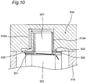
- Fig. 10 shows a sectional view of main part of the gear pump.
- reference signs 505a, 505b denote through holes
- 510 denotes a body
- 530 denotes a cover
- 530a denotes a return passage
- 540 denotes a gasket
- 551, 552 denote clearance grooves
- like component members are designated by like reference signs.
- the cross section of the side plate 505 in Fig. 10 is taken along the line B-B of Fig. 9 .
- the sliding contact surface is desirably formed into such a shape, as shown in Fig. 6 , that the low pressure side clearance groove 451 does not communicate with the through holes 405a, 405b, through which rotary shafts pass, respectively, in the side plate 405.
- part of the operating fluid leaked at the gear side faces is fed to a bearing part 413A (indicated by solid-line arrow) while the rest of the operating fluid flows toward the low pressure side via a gap between the side plate 405 and an end face of the cover 430 (indicated by dotted-line arrow).
- the conventional first gear pump has a drawback that internal leaks at the gear side faces increase, more likely causing deterioration of the pump performance.
- a low pressure side clearance groove 551 and the through holes 505a, 505b are communicated with each other by communicating portions 551a, 551b. This is because the communicating portions 551a, 551b of the clearance groove 551 make it easier for the foreign matters in the operating fluid to escape from the gaps between the gear side faces and the side plate 505 so that wear of the sliding contact surface can be prevented.
- An object of the invention is, therefore, to provide a gear fluid device capable of effectively preventing wear of sliding contact surfaces while keeping a lubricated state of the bearing part with simple construction.
- a gear fluid device of the present invention comprises:
- the groove portion or the recessed portion is provided in the sliding contact surfaces of the sliding contact members (side plate, bearing case, housing, etc.) so as to be positioned radially inside the root diameter of the drive gear and moreover radially outside the rotary shaft hole, into which the rotary shaft of the drive gear is inserted, in such a way that the rotary shaft hole and the clearance groove are not communicated with each other, since the low pressure side and the rotary shaft hole are not communicated with each other, operating fluid leaked at the side face of the drive gear never returns to the low pressure side by passing through the groove portion or the recessed portion.
- the groove portion or the recessed portion is provided in the sliding contact surfaces of the sliding contact members so as to be positioned radially inside the root diameter of the driven gear and moreover radially outside the rotary shaft hole, into which the rotary shaft of the driven gear is inserted, in such a way that the rotary shaft hole and the clearance groove are not communicated with each other, since the low pressure side and the rotary shaft hole are not communicated with each other, operating fluid leaked at the side face of the driven gear never returns to the low pressure side by passing through the groove portion or the recessed portion.
- the sliding contact members are side plates or bearing cases which are placed so as to sandwich both side faces of the drive gear and both side faces of the driven gear, or a housing in which the drive gear and the driven gear are housed.
- the groove portion or the recessed portion of the sliding contact members is provided on the low pressure side of the gear fluid device.
- the groove portion or recessed portion of the sliding contact members (side plate, bearing case, or housing, etc.) is provided on the low pressure side of the gear fluid device, sealing areas for operating fluid on the high pressure side to be sealed by the side faces of the drive gear as well as the driven gear and the sliding contact members do not need to be reduced. That is, since internal leaks at the side faces of the drive gear and the driven gear are never increased, the pump performance can be prevented from adverse effects.
- the groove portion or the recessed portion of the sliding contact members is provided so as to connect to the clearance grooves.
- the groove portion (or recessed portion) of the sliding contact members (side plate, bearing case, or housing, etc.) is provided so as to connect to the clearance groove, foreign matters which have intruded into the gaps between the side faces of the drive gear as well as the driven gear and the sliding contact surfaces of the sliding contact members and which have dropped off into the groove portion (or recessed portion) flow out into the clearance groove along with the operating fluid. Therefore, the removal of foreign matters can be achieved effectively.
- At least one of the groove portions or the recessed portions of the sliding contact members is provided so as to connect to the clearance groove, and another at least one of the groove portions or the recessed portions of the sliding contact members is provided so as to connect to the rotary shaft hole.
- the sliding contact members side plate, bearing case, or housing, etc.
- another at least one of the groove portions (or recessed portions) of the sliding contact members is provided so as to connect to the rotary shaft hole
- foreign matters which have intruded into the gaps between the side faces of the drive gear as well as the driven gear and the sliding contact surfaces of the sliding contact members drop off into the groove portion (or recessed portion) and flow out into both the clearance groove and the rotary shaft hole along with the operating fluid. Therefore, the removal of foreign matters can be achieved more effectively.
- a radially-inner end portion of at least one of the groove portions or the recessed portions connecting to the clearance groove of the sliding contact members is positioned radially inside a radially-outer end portion of the at least one of the groove portions or the recessed portions connecting to the rotary shaft hole of the sliding contact members.
- a radially-inner end portion of at least one of the groove portions (or recessed portions) connecting to the clearance groove of the sliding contact members is positioned radially inside a radially-outer end portion of at least one of the groove portions (or recessed portions) connecting to the rotary shaft hole of the sliding contact members, a foreign-matter removal region by the groove portion (or recessed portion) connecting to the clearance groove and a foreign-matter removal region by the groove portion (or recessed portion) connecting to the rotary shaft hole overlap with each other.
- Fig. 1 is a sectional view of a gear pump as an example of a gear fluid device which is a first embodiment of the present invention.
- the gear pump of this first embodiment includes a body 10 which has two cylindrical spaces having axes parallel to each other and partly overlapping with each other, a drive gear 1 which is a spur gear placed within the body 10, and a driven gear 2 which is placed in the body 10 and which is a spur gear to be mutually engaged with the drive gear 1.
- the body 10 is provided with an inlet port (not shown) and a discharge port (not shown).
- the body 10 is made by using cast iron, aluminum alloy or the like.
- the drive gear 1 and the driven gear 2 are made by using carburizing hardened steel or the like.
- a first side plate 5 and a second side plate 6 as an example of sliding contact members are placed so as to sandwich both side faces of the drive gear 1 and both side faces of the driven gear 2.
- a high-pressure part area on a non-sliding contact surface side of the first side plate 5 and the second side plate 6 is slightly larger than a high-pressure part area on their sliding contact surface side, by which the sliding contact surfaces are to be pressed against the side faces of the drive gear 1 and the driven gear 2 so as to provide as narrow gaps as possible.
- a left end of the body 10 in the figure is covered by the mount member 20 while a right side of the body 10 in the figure is covered by the cover 30.
- the body 10, the mount member 20 and the cover 30 constitute a housing. In this housing, the drive gear 1 and the driven gear 2 having teeth (not shown) to be engaged with each other are contained.
- a first rotary shaft 11 for driving the drive gear 1 is rotatably supported by the cover 30 via a bearing 13A while the other end (left side in Fig. 1 ) of the first rotary shaft 11 is rotatably supported by mount member 20 via a bearing 13B.
- the other-end side coupling part 11a of the first rotary shaft 11 is protruded from the mount member 20, and a drive shaft of an unshown motor is coupled to the coupling part 11a.
- one end (right side in Fig. 1 ) of a second rotary shaft 12 for the driven gear 2 is rotatably supported by the cover 30 via a bearing 14A while the other end (left side in Fig. 1 ) of the second rotary shaft 12 is rotatably supported by the mount member 20 via a bearing 14B.
- reference sign 15 denotes an oil seal.
- Fig. 2 is a plan view of the gear pump as viewed from the sliding contact surface side of the first side plate 5. It is noted that the second side plate 6 is similar in structure to the first side plate 5.
- the first side plate 5 formed into an 8-like shape has a through hole 5a as an example of a rotary shaft hole into which the first rotary shaft 11 (shown in Fig. 1 ) is inserted, a through hole 5b as an example of a rotary shaft hole into which the second rotary shaft 12 (shown in Fig. 1 ) is inserted, a clearance groove 51 extending toward the low-pressure chamber side from a proximity of an engagement portion of the drive gear 1 and the driven gear 2, and a clearance groove 52 extending toward the high-pressure chamber side from a proximity of the engagement portion of the drive gear 1 and the driven gear 2.
- the clearance groove 51 when a confinement region (central portion of the first side plate 5) of operating fluid formed by the first, second side plates 5, 6 and individual teeth of the drive gear 1 and the driven gear 2 in proximity of the engagement portion of the drive gear 1 and the driven gear 2 is expanded so as to come to low pressure, the operating fluid is supplied from the low pressure side of the gear pump to the confinement region to prevent the confinement region from going to negative pressure.
- the clearance groove 52 when the confinement region is contracted along with rotations of the drive gear 1 and the driven gear 2, high-pressure operating fluid within the confinement region is let to escape toward the high pressure side of the gear pump to prevent occurrence of high pressure within the confinement region.
- a groove portion 53 is formed which communicates with the clearance groove 51 of the first side plate 5 and which extends radially inward of a root diameter (indicated by C11) of the drive gear 1 but which does not reach the through hole 5a.
- This groove portion 53 extends radially inward of an intermediate diameter (indicated by C12).
- a groove portion 55 is formed which communicates with the through hole 5a of the first side plate 5 and which extends radially outward of the intermediate diameter (indicated by C12). This groove portion 55 does not communicate with the clearance groove 51.
- the intermediate diameter (indicated by C12) is a diameter equal to 1/2 of a sum of the root diameter of the drive gear 1 and the inner diameter of the through hole 5a.
- a radially-inner end portion of the groove portion 53 connecting to the clearance groove 51 of the first side plate 5 is positioned radially inside a radially-outer end portion of the groove portion 55 connecting to the through hole 5a of the first side plate 5.
- a groove portion 54 is formed which communicates with the clearance groove 51 of the first side plate 5 and which extends radially inward of a root diameter (indicated by C21) of the driven gear 2 but which does not reach the through hole 5b.
- This groove portion 54 extends radially inward of an intermediate diameter (indicated by C22).
- a groove portion 56 is formed which communicates with the through hole 5b of the first side plate 5 and which extends radially outward of the intermediate diameter (indicated by C22). This groove portion 56 does not communicate with the clearance groove 51.
- the intermediate diameter (indicated by C22) is a diameter equal to 1/2 of a sum of the root diameter of the driven gear 2 and the inner diameter of the through hole 5b.
- a radially-inner end portion of the groove portion 54 connecting to the clearance groove 51 of the first side plate 5 is positioned radially inside a radially-outer end portion of the groove portion 56 connecting to the through hole 5b of the first side plate 5.
- the groove portion 53 is formed so as to extend from the low-pressure side clearance groove 51 of the first side plate 5 toward the through hole 5a for the first rotary shaft 11, being terminated on the way leading to the through hole 5a.
- the groove portion 55 is formed also from the through hole 5a toward the low-pressure side clearance groove 51, being terminated on the way leading to the clearance groove 51.
- the groove portion 54 is formed so as to extend from the low-pressure side clearance groove 51 of the first side plate 5 toward the through hole 5b for the second rotary shaft 12, being terminated on the way leading to the through hole 5b.
- the groove portion 56 is formed also from the through hole 5b toward the low-pressure side clearance groove 52, being terminated on the way leading to the clearance groove 52.
- the groove portions 53, 55 are present in an annular region which is radially inside the root diameters (indicated by C11) and which is radially outside the inner diameter of the through hole 5a, and moreover the groove portions 54, 56 are present in an annular region which is radially inside the root diameters (indicated by C21) and which is radially outside the inner diameter of the through hole 5b. That is, the radially-inner end portions of the groove portions 53, 54 connecting to the clearance groove 51 of the first, second side plates 5, 6 are positioned radially inside the radially-outer end portions of the groove portions 55, 56 connecting to the through holes 5a, 5b of the first, second side plates 5, 6.
- the groove portions 53, 55 are provided radially inside the root diameters of the drive gear 1 of the first, second side plates 5, 6 (sliding contact members) and radially outside the through hole 5a into which the first rotary shaft 11 of the drive gear 1 is inserted, in such a way that the through hole 5a and the clearance groove 51 are not communicated with each other.
- the groove portions 54, 56 are provided radially inside the root diameters of the driven gear 2 of the first, second side plates 5, 6 (sliding contact members) and radially outside the through hole 5b into which the second rotary shaft 12 of the driven gear 2 is inserted, in such a way that the through hole 5b and the clearance groove 51 are not communicated with each other.
- the gear pump of the first embodiment it is implementable to effectively prevent wear of the sliding contact surfaces while keeping the lubricated state of the bearing part with simple construction.
- groove portions 53, 54, 55, 56 of the first, second side plates 5, 6 are provided on the low pressure side of the gear pump, sealing areas for operating fluid on the high pressure side to be sealed by the side faces of the drive gear 1 and the driven gear 2 as well as the first, second side plates 5, 6 do not need to be reduced. That is, since internal leaks at the side faces of the drive gear 1 and the driven gear 2 are never increased, the pump performance can be prevented from adverse effects.
- the groove portions 53, 54 of the first, second side plates 5, 6 are provided so as to connect to the clearance groove 51, foreign matters which have intruded into the gaps between the side faces of the drive gear 1 as well as the driven gear 2 and the side faces as sliding contact surfaces of the first, second side plates 5, 6 and which have dropped off into the groove portions 53, 54 flow out into the clearance groove 51 along with the operating fluid. Therefore, the removal of foreign matters can be achieved more effectively.
- the groove portions 53, 54 of the first, second side plates 5, 6 are provided so as to connecting to the clearance groove 51 while the groove portions 55, 56 of the first, second side plates 5, 6 are provided so as to connect to the through holes 5a, 5b, foreign matters which have intruded into the gaps between the side faces of the drive gear 1 as well as the driven gear 2 and the side faces as sliding contact surfaces of the first, second side plates 5, 6 and which have dropped off into the groove portions 53, 54, 55, 56 flow out into both the clearance grooves 51, 52 and the through holes 5a, 5b along with the operating fluid. Therefore, the removal of foreign matters can be achieved more effectively.
- radially-inner end portions of the groove portions 53, 54 connecting to the clearance groove 51 of the first, second side plates 5, 6 are positioned radially inside the radially-outer end portions of the groove portions 55, 56 connecting to the through holes 5a, 5b of the first, second side plates 5, 6, a foreign-matter removal region by the groove portion 53 connecting to the clearance groove 51 and a foreign-matter removal region by the groove portion 55 connecting to the through hole 5a overlap with each other, and moreover a foreign-matter removal region by the groove portion 54 connecting to the clearance groove 51 and a foreign-matter removal region by the groove portion 56 connecting to the through hole 5b overlap with each other.
- the groove portions 53, 54, 55, 56 communicating with only either the rotary shaft-dedicated through holes 5a, 5b or the clearance grooves 51, 52 are provided in the first, second side plates 5, 6 as sliding contact members.
- the number of the groove portions is not particularly limited.
- recessed portions may be provided in annular regions which are radially inside the root diameters of the first, second side plates 5, 6 as sliding contact members and which are radially outside the inner diameters of the through holes 5a, 5b as rotary shaft holes. These recessed portions may be communicated with either the rotary shaft holes or the clearance grooves and moreover may be communicated with neither the rotary shaft holes nor the clearance grooves. In this case, foreign matters which have intruded into the gaps between the side faces of the drive gear as well as the driven gear and the sliding contact surfaces of the sliding contact members drop off into the recessed portions of the sliding contact members.
- the foreign-matter removal region by the groove portion 53 connecting to the clearance groove 51 and the foreign-matter removal region by the groove portion 55 connecting to the through hole 5a overlap with each other, and moreover the foreign-matter removal region by the groove portion 54 connecting to the clearance groove 51 and the foreign-matter removal region by the groove portion 56 connecting to the through hole 5b overlap with each other.
- the invention may be so modified that a foreign-matter removal region by a groove portion (or recessed portion) connecting to a clearance groove and a foreign-matter removal region by a groove portion (or recessed portion) connecting to a through hole do not overlap with each other and are close to each other.
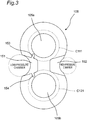
- Fig. 3 is a plan view of a gear pump as an example of a gear fluid device which is a second embodiment of the invention, as viewed from a sliding contact surface side of its first side plate 105.
- the gear pump of this second embodiment is similar in structure to the gear pump of the first embodiment except groove portions of side plates and therefore Fig. 1 is referenced also in this case.
- the second side plate is also similar in structure to the first side plate 105.
- the first side plate 105 formed into an 8-like shape has a through hole 105a as an example of a rotary shaft hole into which the first rotary shaft 11 (shown in Fig. 1 ) is inserted, a through hole 105b as an example of a rotary shaft hole into which the second rotary shaft 12 (shown in Fig. 1 ) is inserted, a clearance groove 151 extending toward the low-pressure chamber side from a proximity of an engagement position of the drive gear 1 (shown in Fig. 1 ) and the driven gear 2 (shown in Fig. 1 ), and a clearance groove 152 extending toward the high-pressure chamber side from a proximity of the engagement position of the drive gear 1 and the driven gear 2.
- a groove portion 153 is formed which communicates with the clearance groove 151 on the low pressure side of the first side plate 105 and which extends from the clearance groove 151 toward the rotary shaft-dedicated through hole 105a up to a proximity of the through hole 105a.
- a groove portion 154 is formed which communicates with the clearance groove 151 on the low pressure side of the first side plate 105 and which extends from the clearance groove 151 toward the rotary shaft-dedicated through hole 105b up to a proximity of the through hole 105b.
- the groove portion 153 is present generally over a region which is radially inside the root diameter (C111) and which is radially outside the inner diameter of the through hole 105a, and moreover the groove portion 154 is present generally over a region which is radially inside the root diameter (C121) and which is radially outside the inner diameter of the through hole 105b.
- the groove portion 153 is present generally over a region which is radially inside the root diameter (C111) and which is radially outside the inner diameter of the through hole 105a
- the groove portion 154 is present generally over a region which is radially inside the root diameter (C121) and which is radially outside the inner diameter of the through hole 105b.
- the gear pump of the above-described second embodiment is capable of effectively preventing wear of sliding contact surfaces while keeping the lubricated state of the bearing part with simple construction.
- the gear pump of this second embodiment can be embodied by taking into account the labor for forming the groove portions and the effects of preventing deterioration of pump performance.
- the groove portions 153, 154 are not communicated with the through holes 105a, 105b, foreign matters never intrude into the bearings 13A, 13B, 14A, 14B (shown in Fig. 1 ), so that damage to the bearings due to foreign matters can be prevented.
- the groove portions 153, 154 communicating with only either the through holes 105a, 105b (rotary shaft holes) or the clearance grooves 151, 152 are provided in the first side plate 105 and the second side plate as sliding contact members.
- the number of groove portions is not limited.
- recessed portions may be provided in annular regions which are radially inside the root diameters of the sliding contact members and which are radially outside the inner diameters of the through holes 105a, 105b. These recessed portions may be communicated with either the rotary shaft holes or the clearance grooves, or may be communicated with neither the rotary shaft holes nor the clearance grooves. In this case, foreign matters which have intruded into the gaps between the side faces of the drive gear as well as the driven gear and the sliding contact surfaces of the sliding contact members drop off into the recessed portions of the sliding contact members.
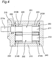
- Fig. 4 is a sectional view of a gear pump as an example of a gear fluid device which is a third embodiment of the invention.
- the gear pump of this third embodiment includes a body 210 which has two cylindrical spaces having axes parallel to each other and partly overlapping with each other, two bearing cases 220, 220 as an example of sliding contact members placed in the body 210 with a specified spacing to each other, a drive gear 201 which is a spur gear placed between the bearing cases 220, 220, and a driven gear 202 which is a spur gear placed between the bearing cases 220, 220 and to be mutually engaged with the drive gear 201.
- the body 210 is provided with an inlet port (not shown) and a discharge port (not shown).
- a high-pressure part area on non-sliding contact surfaces of the bearing cases 220, 220 is slightly larger than a high-pressure part area on their sliding contact surface side.
- the sliding contact surfaces are to be pressed against the side faces of the drive gear 201 and the driven gear 202 so as to provide as narrow gaps as possible.
- a left end of the body 210 in the figure is covered by the mount member 230 while a right side of the body 210 in the figure is covered by the cover 240.
- the body 210, the mount member 230 and the cover 240 constitute a housing. In this housing, the drive gear 201 and the driven gear 202 to be engaged with each other are contained.
- One end (right side in Fig. 4 ) of a first rotary shaft 211 for driving the drive gear 201 is rotatably supported by a bearing case 220 via a bearing 213A while the other end (left side in Fig. 4 ) of the first rotary shaft 211 is rotatably supported by another bearing case 220 via a bearing 213B.
- the other-end side coupling part 211a of the first rotary shaft 211 is protruded from the mount member 230, and a drive shaft of an unshown motor is coupled to the coupling part 211a.
- one end (right side in Fig. 4 ) of a first rotary shaft 211 for driving the drive gear 201 is rotatably supported by a bearing case 220 via a bearing 213A while the other end (left side in Fig. 4 ) of the first rotary shaft 211 is rotatably supported by another bearing case 220 via a bearing 213B.
- a second rotary shaft 212 for the driven gear 202 is rotatably supported by the bearing case 220 via a bearing 214A while the other end (left side in Fig. 4 ) of the second rotary shaft 212 is rotatably supported by the bearing case 220 via a bearing 214B.
- reference sign 215 denotes an oil seal.
- the sliding contact surface side of the bearing cases 220, 220 (sliding contact members) to be brought into sliding contact with the side faces of the drive gear 201 and the driven gear 202 is similar in structure to that of the first, second side plates of the first embodiment or the second embodiment.
- the gear pump of the third embodiment has the same effects as the gear pump of the first embodiment.
- the side plates or the bearing cases have been mentioned in the first to third embodiments.
- the present invention is applicable also to sliding contact surfaces of mount members or covers facing gear side faces in even pumps of the fixed gap method using neither the side plates nor the bearing cases.
- Fig. 5 is a sectional view of a gear pump as an example of a gear fluid device which is a fourth embodiment of the invention.
- the gear pump of this fourth embodiment is similar in structure to the gear pump of the first embodiment except that neither the side plates nor the bearing cases are included and that the mount member and the cover are different therefrom.
- the gear pump of the fourth embodiment includes a body 310 which has two cylindrical spaces having axes parallel to each other and partly overlapping with each other, a drive gear 301 which is a spur gear placed within the body 310, and a driven gear 302 which is placed in the body 310 and which is a spur gear to be mutually engaged with the drive gear 301.
- the body 310 is provided with an inlet port (not shown) and a discharge port (not shown).
- a left end of the body 310 in the figure is covered by a mount member 320 while a right side of the body 310 in the figure is covered by a cover 330.
- the body 310, the mount member 320 and the cover 330 constitute a housing.
- the drive gear 301 and the driven gear 302 having teeth (not shown) to be engaged with each other are contained.
- mount member 320 and the cover 330 as an example of sliding contact members placed so as to sandwich both side faces of the drive gear 301 and both side faces of the driven gear 302
- sealing is performed between the side faces of the drive gear 301 as well as the driven gear 302 and the sliding contact surface of the mount member 320 as well as between the side surfaces of the drive gear 301 and the driven gear 302 and the sliding contact surface of the cover 330, by which a low-pressure chamber communicating with the inlet port and a high-pressure chamber communicating with the discharge port are formed.
- One end (right side in Fig. 5 ) of a first rotary shaft 311 for driving the drive gear 301 is rotatably supported by the cover 330 via a bearing 313A while the other end (left side in Fig. 5 ) of the first rotary shaft 311 is rotatably supported by the mount member 320 via a bearing 313B.
- the other-end side coupling part 311a of the first rotary shaft 311 is protruded from the mount member 320, and a drive shaft of an unshown motor is coupled to the coupling part 311a.
- one end (right side in Fig. 5 ) of a first rotary shaft 311 for driving the drive gear 301 is rotatably supported by the cover 330 via a bearing 313A while the other end (left side in Fig. 5 ) of the first rotary shaft 311 is rotatably supported by the mount member 320 via a bearing 313B.
- the other-end side coupling part 311a of the first rotary shaft 311
- a second rotary shaft 312 for the driven gear 302 is rotatably supported by the cover 330 via a bearing 314A while the other end (left side in Fig. 5 ) of the second rotary shaft 312 is rotatably supported by the mount member 320 via a bearing 314B.
- reference sign 315 denotes an oil seal.
- the sliding contact surface side of the mount member 320 and the cover 330 to be brought into sliding contact with the side faces of the drive gear 301 and the driven gear 302 is similar in structure to that of the first, second side plates of the first embodiment or the second embodiment.
- the gear pump of the fourth embodiment has the same effects as the gear pump of the first embodiment.
- gear pumps as an example of the gear fluid device.
- present invention is applicable also to gear motors because gear motors are similar in structure to gear pumps except that their actions are reverse to each other.
- the first to fourth embodiments have been described on gear fluid devices including, as the sliding contact members, the first, second side plates 5, 6, 105 and the bearing cases 220, 220, as well as the mount member 320 and the cover 330.
- the sliding contact members need only to be members having sliding contact surfaces to be brought into sliding contact with the side face of the drive gear and the side face of the driven gear.
- the first to fourth embodiments have been described on gear pumps in which the drive gears 1, 201, 301 and the driven gears 2, 202, 302 are spur gears.
- the invention may also be applied to gear fluid devices in which the drive gear and the driven gear are helical gears.
- the first to fourth embodiments have been described on gear pumps which are provided with the groove portions 53, 54, 153, 154 communicating with the clearance grooves 51, 151 on the low pressure side of the first, second side plates 5, 6, 105 as well as the groove portions 55, 56 communicating with the through hole 5a.
- the groove portions (or recessed portions) to be provided in the side plates may be non-communicated with the clearance grooves or may be provided not on the low pressure side of the gear pumps but on the high pressure side of the gear pump.
- the groove portions or recessed portions are provided radially inside the root diameters of the drive gear and the driven gear and moreover radially outside the rotary shaft holes in such a way that the rotary shaft holes and the clearance grooves are not communicated with each other, it is achievable to effectively prevent wear of sliding contact surfaces while keeping the lubricated state of the bearing part.
Landscapes
- Engineering & Computer Science (AREA)
- Mechanical Engineering (AREA)
- General Engineering & Computer Science (AREA)
- Rotary Pumps (AREA)
- Details And Applications Of Rotary Liquid Pumps (AREA)
- Valve Device For Special Equipments (AREA)
Applications Claiming Priority (3)
| Application Number | Priority Date | Filing Date | Title |
|---|---|---|---|
| JP2013193276 | 2013-09-18 | ||
| JP2014147177A JP5783305B2 (ja) | 2013-09-18 | 2014-07-17 | ギヤ流体装置 |
| PCT/JP2014/071332 WO2015040985A1 (fr) | 2013-09-18 | 2014-08-12 | Dispositif à fluide pour engrenage |
Publications (4)
| Publication Number | Publication Date |
|---|---|
| EP3048303A1 true EP3048303A1 (fr) | 2016-07-27 |
| EP3048303A4 EP3048303A4 (fr) | 2017-04-19 |
| EP3048303B1 EP3048303B1 (fr) | 2022-12-28 |
| EP3048303B8 EP3048303B8 (fr) | 2023-02-08 |
Family
ID=52688642
Family Applications (1)
| Application Number | Title | Priority Date | Filing Date |
|---|---|---|---|
| EP14845988.6A Active EP3048303B8 (fr) | 2013-09-18 | 2014-08-12 | Dispositif à fluide pour engrenage |
Country Status (6)
| Country | Link |
|---|---|
| EP (1) | EP3048303B8 (fr) |
| JP (1) | JP5783305B2 (fr) |
| CN (1) | CN105492774B (fr) |
| ES (1) | ES2938841T3 (fr) |
| TW (1) | TWI545265B (fr) |
| WO (1) | WO2015040985A1 (fr) |
Cited By (3)
| Publication number | Priority date | Publication date | Assignee | Title |
|---|---|---|---|---|
| WO2018019587A1 (fr) * | 2016-07-26 | 2018-02-01 | Robert Bosch Gmbh | Pompe à engrenages extérieurs pour un système de récuperation de chaleur perdue |
| WO2018114332A1 (fr) * | 2016-12-21 | 2018-06-28 | Robert Bosch Gmbh | Pompe à fluide pour un système de récupération de chaleur perdue |
| US11143197B2 (en) | 2017-09-06 | 2021-10-12 | Ebm-Papst Mulfingen Gmbh & Co. Kg | Covered radial fan wheel with a periodically and asymmetrically shaped plate |
Families Citing this family (3)
| Publication number | Priority date | Publication date | Assignee | Title |
|---|---|---|---|---|
| CN107228179A (zh) * | 2017-04-13 | 2017-10-03 | 天津市汇晶丰精密机械有限公司 | 一种深海探测马达 |
| CN108799101A (zh) * | 2018-06-15 | 2018-11-13 | 哈尔滨理工大学 | 一种外啮合齿轮泵用新型浮动轴套 |
| CN110761998B (zh) * | 2019-11-12 | 2022-11-11 | 浙江麦得机器有限公司 | 一种基于液压系统的内缩型隔离补偿式齿轮泵 |
Family Cites Families (15)
| Publication number | Priority date | Publication date | Assignee | Title |
|---|---|---|---|---|
| US2354992A (en) * | 1941-11-11 | 1944-08-01 | Westinghouse Electric & Mfg Co | Gear pump |
| US2665641A (en) * | 1949-06-18 | 1954-01-12 | Borg Warner | Pump, pressure loaded, with differential valve |
| US2718758A (en) * | 1949-07-15 | 1955-09-27 | Borg Warner | Variable ratio hydrostatic transmission |
| US3303792A (en) * | 1964-04-20 | 1967-02-14 | Roper Ind Inc | Gear pump with trapping reliefs |
| GB1232590A (fr) * | 1967-08-21 | 1971-05-19 | ||
| JPS5842629Y2 (ja) * | 1978-08-31 | 1983-09-27 | カヤバ工業株式会社 | 歯車ポンプ又はモ−タ |
| JP2527929B2 (ja) * | 1985-05-20 | 1996-08-28 | カヤバ工業 株式会社 | ギヤポンプの低圧潤滑装置 |
| JP2613051B2 (ja) * | 1987-05-07 | 1997-05-21 | カヤバ工業株式会社 | ギヤポンプ |
| JP2743616B2 (ja) * | 1991-04-23 | 1998-04-22 | 株式会社島津製作所 | ギヤポンプ |
| JP3407331B2 (ja) | 1993-05-06 | 2003-05-19 | 株式会社島津製作所 | 歯車ポンプ・モータ |
| JP3433533B2 (ja) | 1994-10-31 | 2003-08-04 | 株式会社島津製作所 | 歯車ポンプ又はモータ |
| JPH1182323A (ja) * | 1997-09-11 | 1999-03-26 | Hitachi Ltd | 燃料ポンプ |
| PT1540184E (pt) * | 2002-06-03 | 2015-08-20 | M & M Technologies Inc | Bomba de engrenagens |
| US20080240968A1 (en) * | 2004-02-13 | 2008-10-02 | Chiu Hing L | Low Cost Gear Fuel Pump |
| DE102009012916A1 (de) * | 2009-03-12 | 2010-09-16 | Robert Bosch Gmbh | Hydraulische Zahnradmaschine |
-
2014
- 2014-07-17 JP JP2014147177A patent/JP5783305B2/ja not_active Expired - Fee Related
- 2014-08-12 ES ES14845988T patent/ES2938841T3/es active Active
- 2014-08-12 EP EP14845988.6A patent/EP3048303B8/fr active Active
- 2014-08-12 CN CN201480048335.9A patent/CN105492774B/zh not_active Expired - Fee Related
- 2014-08-12 WO PCT/JP2014/071332 patent/WO2015040985A1/fr not_active Ceased
- 2014-09-16 TW TW103131969A patent/TWI545265B/zh not_active IP Right Cessation
Non-Patent Citations (1)
| Title |
|---|
| See references of WO2015040985A1 * |
Cited By (3)
| Publication number | Priority date | Publication date | Assignee | Title |
|---|---|---|---|---|
| WO2018019587A1 (fr) * | 2016-07-26 | 2018-02-01 | Robert Bosch Gmbh | Pompe à engrenages extérieurs pour un système de récuperation de chaleur perdue |
| WO2018114332A1 (fr) * | 2016-12-21 | 2018-06-28 | Robert Bosch Gmbh | Pompe à fluide pour un système de récupération de chaleur perdue |
| US11143197B2 (en) | 2017-09-06 | 2021-10-12 | Ebm-Papst Mulfingen Gmbh & Co. Kg | Covered radial fan wheel with a periodically and asymmetrically shaped plate |
Also Published As
| Publication number | Publication date |
|---|---|
| JP5783305B2 (ja) | 2015-09-24 |
| EP3048303B8 (fr) | 2023-02-08 |
| TW201529984A (zh) | 2015-08-01 |
| EP3048303B1 (fr) | 2022-12-28 |
| WO2015040985A1 (fr) | 2015-03-26 |
| TWI545265B (zh) | 2016-08-11 |
| CN105492774B (zh) | 2017-05-03 |
| JP2015083831A (ja) | 2015-04-30 |
| ES2938841T3 (es) | 2023-04-17 |
| CN105492774A (zh) | 2016-04-13 |
| EP3048303A4 (fr) | 2017-04-19 |
Similar Documents
| Publication | Publication Date | Title |
|---|---|---|
| EP3048303B1 (fr) | Dispositif à fluide pour engrenage | |
| US10954790B2 (en) | Stepped sealing device circumferential pumping groove | |
| JP5904961B2 (ja) | スクリュー圧縮機 | |
| CN1224814C (zh) | 封闭式电动压缩机 | |
| US9366253B2 (en) | Scroll compressor and processing method of scroll including a projection on a tip seal and a hole in a tip seal groove | |
| JP2016156310A (ja) | 開放型圧縮機 | |
| EP3508723B1 (fr) | Compresseur à spirales | |
| TWI408295B (zh) | 旋轉機 | |
| EP3564532B1 (fr) | Compresseur à vis | |
| US7717689B2 (en) | Rotor apparatus of pump including a drive shaft with a plurality of arcuate circumferential surface sections | |
| EP3546699B1 (fr) | Élément d'étanchéité | |
| US7467934B2 (en) | Axial piston engine with integrated filling pump | |
| CN105339665B (zh) | 涡旋式流体设备及其垫圈 | |
| US10082140B2 (en) | Scroll compressor having compression chamber communicating with discharge port via a gap between recessed part formed on front face of movable-side plate and tip of fixed-side lap | |
| JP2014047751A (ja) | 内接歯車ポンプ | |
| JP6229391B2 (ja) | ウォータポンプ | |
| JP7539828B2 (ja) | 油冷式スクリュ圧縮機の軸封構造 | |
| JP6596233B2 (ja) | 密閉型スクロール圧縮機 | |
| JP2025038542A (ja) | スクリュ圧縮機及びガス圧縮設備 | |
| JP2009235948A (ja) | 圧縮機 | |
| EP3115608A1 (fr) | Dispositif de pompe | |
| WO2025263415A1 (fr) | Pompe à engrenage interne | |
| JP2025038543A (ja) | スクリュ圧縮機及びガス圧縮設備 | |
| WO2018135444A1 (fr) | Compresseur à vis refroidi à l'huile | |
| JP2009222150A (ja) | 軸受け構造および圧縮機 |
Legal Events
| Date | Code | Title | Description |
|---|---|---|---|
| PUAI | Public reference made under article 153(3) epc to a published international application that has entered the european phase |
Free format text: ORIGINAL CODE: 0009012 |
|
| 17P | Request for examination filed |
Effective date: 20160225 |
|
| AK | Designated contracting states |
Kind code of ref document: A1 Designated state(s): AL AT BE BG CH CY CZ DE DK EE ES FI FR GB GR HR HU IE IS IT LI LT LU LV MC MK MT NL NO PL PT RO RS SE SI SK SM TR |
|
| AX | Request for extension of the european patent |
Extension state: BA ME |
|
| DAX | Request for extension of the european patent (deleted) | ||
| A4 | Supplementary search report drawn up and despatched |
Effective date: 20170322 |
|
| RIC1 | Information provided on ipc code assigned before grant |
Ipc: F03C 2/08 20060101ALI20170316BHEP Ipc: F04C 2/18 20060101AFI20170316BHEP Ipc: F04C 13/00 20060101ALI20170316BHEP Ipc: F04C 2/08 20060101ALI20170316BHEP Ipc: F01C 21/10 20060101ALI20170316BHEP Ipc: F04C 15/00 20060101ALI20170316BHEP Ipc: F04C 29/02 20060101ALI20170316BHEP |
|
| STAA | Information on the status of an ep patent application or granted ep patent |
Free format text: STATUS: EXAMINATION IS IN PROGRESS |
|
| 17Q | First examination report despatched |
Effective date: 20200820 |
|
| GRAP | Despatch of communication of intention to grant a patent |
Free format text: ORIGINAL CODE: EPIDOSNIGR1 |
|
| STAA | Information on the status of an ep patent application or granted ep patent |
Free format text: STATUS: GRANT OF PATENT IS INTENDED |
|
| INTG | Intention to grant announced |
Effective date: 20220909 |
|
| GRAS | Grant fee paid |
Free format text: ORIGINAL CODE: EPIDOSNIGR3 |
|
| GRAA | (expected) grant |
Free format text: ORIGINAL CODE: 0009210 |
|
| STAA | Information on the status of an ep patent application or granted ep patent |
Free format text: STATUS: THE PATENT HAS BEEN GRANTED |
|
| AK | Designated contracting states |
Kind code of ref document: B1 Designated state(s): AL AT BE BG CH CY CZ DE DK EE ES FI FR GB GR HR HU IE IS IT LI LT LU LV MC MK MT NL NO PL PT RO RS SE SI SK SM TR |
|
| REG | Reference to a national code |
Ref country code: GB Ref legal event code: FG4D |
|
| REG | Reference to a national code |
Ref country code: CH Ref legal event code: EP |
|
| REG | Reference to a national code |
Ref country code: DE Ref legal event code: R096 Ref document number: 602014085955 Country of ref document: DE |
|
| REG | Reference to a national code |
Ref country code: CH Ref legal event code: PK Free format text: BERICHTIGUNG B8 |
|
| REG | Reference to a national code |
Ref country code: AT Ref legal event code: REF Ref document number: 1540649 Country of ref document: AT Kind code of ref document: T Effective date: 20230115 |
|
| RAP4 | Party data changed (patent owner data changed or rights of a patent transferred) |
Owner name: DAIKIN INDUSTRIES, LTD. |
|
| REG | Reference to a national code |
Ref country code: IE Ref legal event code: FG4D |
|
| REG | Reference to a national code |
Ref country code: LT Ref legal event code: MG9D |
|
| REG | Reference to a national code |
Ref country code: ES Ref legal event code: FG2A Ref document number: 2938841 Country of ref document: ES Kind code of ref document: T3 Effective date: 20230417 |
|
| PG25 | Lapsed in a contracting state [announced via postgrant information from national office to epo] |
Ref country code: SE Free format text: LAPSE BECAUSE OF FAILURE TO SUBMIT A TRANSLATION OF THE DESCRIPTION OR TO PAY THE FEE WITHIN THE PRESCRIBED TIME-LIMIT Effective date: 20221228 Ref country code: NO Free format text: LAPSE BECAUSE OF FAILURE TO SUBMIT A TRANSLATION OF THE DESCRIPTION OR TO PAY THE FEE WITHIN THE PRESCRIBED TIME-LIMIT Effective date: 20230328 Ref country code: LT Free format text: LAPSE BECAUSE OF FAILURE TO SUBMIT A TRANSLATION OF THE DESCRIPTION OR TO PAY THE FEE WITHIN THE PRESCRIBED TIME-LIMIT Effective date: 20221228 Ref country code: FI Free format text: LAPSE BECAUSE OF FAILURE TO SUBMIT A TRANSLATION OF THE DESCRIPTION OR TO PAY THE FEE WITHIN THE PRESCRIBED TIME-LIMIT Effective date: 20221228 |
|
| REG | Reference to a national code |
Ref country code: NL Ref legal event code: MP Effective date: 20221228 |
|
| REG | Reference to a national code |
Ref country code: AT Ref legal event code: MK05 Ref document number: 1540649 Country of ref document: AT Kind code of ref document: T Effective date: 20221228 |
|
| PG25 | Lapsed in a contracting state [announced via postgrant information from national office to epo] |
Ref country code: RS Free format text: LAPSE BECAUSE OF FAILURE TO SUBMIT A TRANSLATION OF THE DESCRIPTION OR TO PAY THE FEE WITHIN THE PRESCRIBED TIME-LIMIT Effective date: 20221228 Ref country code: LV Free format text: LAPSE BECAUSE OF FAILURE TO SUBMIT A TRANSLATION OF THE DESCRIPTION OR TO PAY THE FEE WITHIN THE PRESCRIBED TIME-LIMIT Effective date: 20221228 Ref country code: HR Free format text: LAPSE BECAUSE OF FAILURE TO SUBMIT A TRANSLATION OF THE DESCRIPTION OR TO PAY THE FEE WITHIN THE PRESCRIBED TIME-LIMIT Effective date: 20221228 Ref country code: GR Free format text: LAPSE BECAUSE OF FAILURE TO SUBMIT A TRANSLATION OF THE DESCRIPTION OR TO PAY THE FEE WITHIN THE PRESCRIBED TIME-LIMIT Effective date: 20230329 |
|
| PG25 | Lapsed in a contracting state [announced via postgrant information from national office to epo] |
Ref country code: NL Free format text: LAPSE BECAUSE OF FAILURE TO SUBMIT A TRANSLATION OF THE DESCRIPTION OR TO PAY THE FEE WITHIN THE PRESCRIBED TIME-LIMIT Effective date: 20221228 |
|
| P01 | Opt-out of the competence of the unified patent court (upc) registered |
Effective date: 20230525 |
|
| PG25 | Lapsed in a contracting state [announced via postgrant information from national office to epo] |
Ref country code: SM Free format text: LAPSE BECAUSE OF FAILURE TO SUBMIT A TRANSLATION OF THE DESCRIPTION OR TO PAY THE FEE WITHIN THE PRESCRIBED TIME-LIMIT Effective date: 20221228 Ref country code: RO Free format text: LAPSE BECAUSE OF FAILURE TO SUBMIT A TRANSLATION OF THE DESCRIPTION OR TO PAY THE FEE WITHIN THE PRESCRIBED TIME-LIMIT Effective date: 20221228 Ref country code: PT Free format text: LAPSE BECAUSE OF FAILURE TO SUBMIT A TRANSLATION OF THE DESCRIPTION OR TO PAY THE FEE WITHIN THE PRESCRIBED TIME-LIMIT Effective date: 20230428 Ref country code: EE Free format text: LAPSE BECAUSE OF FAILURE TO SUBMIT A TRANSLATION OF THE DESCRIPTION OR TO PAY THE FEE WITHIN THE PRESCRIBED TIME-LIMIT Effective date: 20221228 Ref country code: CZ Free format text: LAPSE BECAUSE OF FAILURE TO SUBMIT A TRANSLATION OF THE DESCRIPTION OR TO PAY THE FEE WITHIN THE PRESCRIBED TIME-LIMIT Effective date: 20221228 Ref country code: AT Free format text: LAPSE BECAUSE OF FAILURE TO SUBMIT A TRANSLATION OF THE DESCRIPTION OR TO PAY THE FEE WITHIN THE PRESCRIBED TIME-LIMIT Effective date: 20221228 |
|
| PG25 | Lapsed in a contracting state [announced via postgrant information from national office to epo] |
Ref country code: SK Free format text: LAPSE BECAUSE OF FAILURE TO SUBMIT A TRANSLATION OF THE DESCRIPTION OR TO PAY THE FEE WITHIN THE PRESCRIBED TIME-LIMIT Effective date: 20221228 Ref country code: PL Free format text: LAPSE BECAUSE OF FAILURE TO SUBMIT A TRANSLATION OF THE DESCRIPTION OR TO PAY THE FEE WITHIN THE PRESCRIBED TIME-LIMIT Effective date: 20221228 Ref country code: IS Free format text: LAPSE BECAUSE OF FAILURE TO SUBMIT A TRANSLATION OF THE DESCRIPTION OR TO PAY THE FEE WITHIN THE PRESCRIBED TIME-LIMIT Effective date: 20230428 Ref country code: AL Free format text: LAPSE BECAUSE OF FAILURE TO SUBMIT A TRANSLATION OF THE DESCRIPTION OR TO PAY THE FEE WITHIN THE PRESCRIBED TIME-LIMIT Effective date: 20221228 |
|
| REG | Reference to a national code |
Ref country code: DE Ref legal event code: R097 Ref document number: 602014085955 Country of ref document: DE |
|
| PG25 | Lapsed in a contracting state [announced via postgrant information from national office to epo] |
Ref country code: DK Free format text: LAPSE BECAUSE OF FAILURE TO SUBMIT A TRANSLATION OF THE DESCRIPTION OR TO PAY THE FEE WITHIN THE PRESCRIBED TIME-LIMIT Effective date: 20221228 |
|
| PGFP | Annual fee paid to national office [announced via postgrant information from national office to epo] |
Ref country code: IT Payment date: 20230825 Year of fee payment: 10 |
|
| PLBE | No opposition filed within time limit |
Free format text: ORIGINAL CODE: 0009261 |
|
| STAA | Information on the status of an ep patent application or granted ep patent |
Free format text: STATUS: NO OPPOSITION FILED WITHIN TIME LIMIT |
|
| PGFP | Annual fee paid to national office [announced via postgrant information from national office to epo] |
Ref country code: DE Payment date: 20230821 Year of fee payment: 10 |
|
| 26N | No opposition filed |
Effective date: 20230929 |
|
| PGFP | Annual fee paid to national office [announced via postgrant information from national office to epo] |
Ref country code: ES Payment date: 20231027 Year of fee payment: 10 |
|
| PG25 | Lapsed in a contracting state [announced via postgrant information from national office to epo] |
Ref country code: SI Free format text: LAPSE BECAUSE OF FAILURE TO SUBMIT A TRANSLATION OF THE DESCRIPTION OR TO PAY THE FEE WITHIN THE PRESCRIBED TIME-LIMIT Effective date: 20221228 |
|
| PG25 | Lapsed in a contracting state [announced via postgrant information from national office to epo] |
Ref country code: MC Free format text: LAPSE BECAUSE OF FAILURE TO SUBMIT A TRANSLATION OF THE DESCRIPTION OR TO PAY THE FEE WITHIN THE PRESCRIBED TIME-LIMIT Effective date: 20221228 |
|
| REG | Reference to a national code |
Ref country code: CH Ref legal event code: PL |
|
| PG25 | Lapsed in a contracting state [announced via postgrant information from national office to epo] |
Ref country code: MC Free format text: LAPSE BECAUSE OF FAILURE TO SUBMIT A TRANSLATION OF THE DESCRIPTION OR TO PAY THE FEE WITHIN THE PRESCRIBED TIME-LIMIT Effective date: 20221228 |
|
| PG25 | Lapsed in a contracting state [announced via postgrant information from national office to epo] |
Ref country code: LU Free format text: LAPSE BECAUSE OF NON-PAYMENT OF DUE FEES Effective date: 20230812 |
|
| GBPC | Gb: european patent ceased through non-payment of renewal fee |
Effective date: 20230812 |
|
| PG25 | Lapsed in a contracting state [announced via postgrant information from national office to epo] |
Ref country code: LU Free format text: LAPSE BECAUSE OF NON-PAYMENT OF DUE FEES Effective date: 20230812 Ref country code: CH Free format text: LAPSE BECAUSE OF NON-PAYMENT OF DUE FEES Effective date: 20230831 |
|
| REG | Reference to a national code |
Ref country code: BE Ref legal event code: MM Effective date: 20230831 |
|
| REG | Reference to a national code |
Ref country code: IE Ref legal event code: MM4A |
|
| PG25 | Lapsed in a contracting state [announced via postgrant information from national office to epo] |
Ref country code: IE Free format text: LAPSE BECAUSE OF NON-PAYMENT OF DUE FEES Effective date: 20230812 |
|
| PG25 | Lapsed in a contracting state [announced via postgrant information from national office to epo] |
Ref country code: GB Free format text: LAPSE BECAUSE OF NON-PAYMENT OF DUE FEES Effective date: 20230812 |
|
| PG25 | Lapsed in a contracting state [announced via postgrant information from national office to epo] |
Ref country code: IE Free format text: LAPSE BECAUSE OF NON-PAYMENT OF DUE FEES Effective date: 20230812 Ref country code: GB Free format text: LAPSE BECAUSE OF NON-PAYMENT OF DUE FEES Effective date: 20230812 Ref country code: FR Free format text: LAPSE BECAUSE OF NON-PAYMENT OF DUE FEES Effective date: 20230831 |
|
| PG25 | Lapsed in a contracting state [announced via postgrant information from national office to epo] |
Ref country code: BE Free format text: LAPSE BECAUSE OF NON-PAYMENT OF DUE FEES Effective date: 20230831 |
|
| PG25 | Lapsed in a contracting state [announced via postgrant information from national office to epo] |
Ref country code: BG Free format text: LAPSE BECAUSE OF FAILURE TO SUBMIT A TRANSLATION OF THE DESCRIPTION OR TO PAY THE FEE WITHIN THE PRESCRIBED TIME-LIMIT Effective date: 20221228 |
|
| PG25 | Lapsed in a contracting state [announced via postgrant information from national office to epo] |
Ref country code: BG Free format text: LAPSE BECAUSE OF FAILURE TO SUBMIT A TRANSLATION OF THE DESCRIPTION OR TO PAY THE FEE WITHIN THE PRESCRIBED TIME-LIMIT Effective date: 20221228 |
|
| REG | Reference to a national code |
Ref country code: DE Ref legal event code: R119 Ref document number: 602014085955 Country of ref document: DE |
|
| PG25 | Lapsed in a contracting state [announced via postgrant information from national office to epo] |
Ref country code: DE Free format text: LAPSE BECAUSE OF NON-PAYMENT OF DUE FEES Effective date: 20250301 |
|
| PG25 | Lapsed in a contracting state [announced via postgrant information from national office to epo] |
Ref country code: IT Free format text: LAPSE BECAUSE OF NON-PAYMENT OF DUE FEES Effective date: 20240812 |
|
| PG25 | Lapsed in a contracting state [announced via postgrant information from national office to epo] |
Ref country code: CY Free format text: LAPSE BECAUSE OF FAILURE TO SUBMIT A TRANSLATION OF THE DESCRIPTION OR TO PAY THE FEE WITHIN THE PRESCRIBED TIME-LIMIT; INVALID AB INITIO Effective date: 20140812 |
|
| PG25 | Lapsed in a contracting state [announced via postgrant information from national office to epo] |
Ref country code: HU Free format text: LAPSE BECAUSE OF FAILURE TO SUBMIT A TRANSLATION OF THE DESCRIPTION OR TO PAY THE FEE WITHIN THE PRESCRIBED TIME-LIMIT; INVALID AB INITIO Effective date: 20140812 |
|
| REG | Reference to a national code |
Ref country code: ES Ref legal event code: FD2A Effective date: 20250929 |
|
| PG25 | Lapsed in a contracting state [announced via postgrant information from national office to epo] |
Ref country code: ES Free format text: LAPSE BECAUSE OF NON-PAYMENT OF DUE FEES Effective date: 20240813 |
|
| PG25 | Lapsed in a contracting state [announced via postgrant information from national office to epo] |
Ref country code: TR Free format text: LAPSE BECAUSE OF FAILURE TO SUBMIT A TRANSLATION OF THE DESCRIPTION OR TO PAY THE FEE WITHIN THE PRESCRIBED TIME-LIMIT Effective date: 20221228 |