EP3048343A1 - Bague d'étanchéité d'arbre inter à plusieurs étages - Google Patents
Bague d'étanchéité d'arbre inter à plusieurs étages Download PDFInfo
- Publication number
- EP3048343A1 EP3048343A1 EP16152097.8A EP16152097A EP3048343A1 EP 3048343 A1 EP3048343 A1 EP 3048343A1 EP 16152097 A EP16152097 A EP 16152097A EP 3048343 A1 EP3048343 A1 EP 3048343A1
- Authority
- EP
- European Patent Office
- Prior art keywords
- seal
- protrusion
- stages
- notch
- spring
- Prior art date
- Legal status (The legal status is an assumption and is not a legal conclusion. Google has not performed a legal analysis and makes no representation as to the accuracy of the status listed.)
- Granted
Links
Images







Classifications
-
- F—MECHANICAL ENGINEERING; LIGHTING; HEATING; WEAPONS; BLASTING
- F02—COMBUSTION ENGINES; HOT-GAS OR COMBUSTION-PRODUCT ENGINE PLANTS
- F02C—GAS-TURBINE PLANTS; AIR INTAKES FOR JET-PROPULSION PLANTS; CONTROLLING FUEL SUPPLY IN AIR-BREATHING JET-PROPULSION PLANTS
- F02C7/00—Features, components parts, details or accessories, not provided for in, or of interest apart form groups F02C1/00 - F02C6/00; Air intakes for jet-propulsion plants
- F02C7/28—Arrangement of seals
-
- F—MECHANICAL ENGINEERING; LIGHTING; HEATING; WEAPONS; BLASTING
- F01—MACHINES OR ENGINES IN GENERAL; ENGINE PLANTS IN GENERAL; STEAM ENGINES
- F01D—NON-POSITIVE DISPLACEMENT MACHINES OR ENGINES, e.g. STEAM TURBINES
- F01D11/00—Preventing or minimising internal leakage of working-fluid, e.g. between stages
- F01D11/003—Preventing or minimising internal leakage of working-fluid, e.g. between stages by packing rings; Mechanical seals
-
- F—MECHANICAL ENGINEERING; LIGHTING; HEATING; WEAPONS; BLASTING
- F01—MACHINES OR ENGINES IN GENERAL; ENGINE PLANTS IN GENERAL; STEAM ENGINES
- F01D—NON-POSITIVE DISPLACEMENT MACHINES OR ENGINES, e.g. STEAM TURBINES
- F01D25/00—Component parts, details, or accessories, not provided for in, or of interest apart from, other groups
- F01D25/18—Lubricating arrangements
- F01D25/183—Sealing means
-
- F—MECHANICAL ENGINEERING; LIGHTING; HEATING; WEAPONS; BLASTING
- F16—ENGINEERING ELEMENTS AND UNITS; GENERAL MEASURES FOR PRODUCING AND MAINTAINING EFFECTIVE FUNCTIONING OF MACHINES OR INSTALLATIONS; THERMAL INSULATION IN GENERAL
- F16J—PISTONS; CYLINDERS; SEALINGS
- F16J15/00—Sealings
- F16J15/16—Sealings between relatively-moving surfaces
- F16J15/26—Sealings between relatively-moving surfaces with stuffing-boxes for rigid sealing rings
- F16J15/30—Sealings between relatively-moving surfaces with stuffing-boxes for rigid sealing rings with sealing rings made of carbon
-
- F—MECHANICAL ENGINEERING; LIGHTING; HEATING; WEAPONS; BLASTING
- F16—ENGINEERING ELEMENTS AND UNITS; GENERAL MEASURES FOR PRODUCING AND MAINTAINING EFFECTIVE FUNCTIONING OF MACHINES OR INSTALLATIONS; THERMAL INSULATION IN GENERAL
- F16J—PISTONS; CYLINDERS; SEALINGS
- F16J15/00—Sealings
- F16J15/16—Sealings between relatively-moving surfaces
- F16J15/32—Sealings between relatively-moving surfaces with elastic sealings, e.g. O-rings
- F16J15/3268—Mounting of sealing rings
-
- F—MECHANICAL ENGINEERING; LIGHTING; HEATING; WEAPONS; BLASTING
- F16—ENGINEERING ELEMENTS AND UNITS; GENERAL MEASURES FOR PRODUCING AND MAINTAINING EFFECTIVE FUNCTIONING OF MACHINES OR INSTALLATIONS; THERMAL INSULATION IN GENERAL
- F16J—PISTONS; CYLINDERS; SEALINGS
- F16J15/00—Sealings
- F16J15/44—Free-space packings
- F16J15/441—Free-space packings with floating ring
-
- F—MECHANICAL ENGINEERING; LIGHTING; HEATING; WEAPONS; BLASTING
- F16—ENGINEERING ELEMENTS AND UNITS; GENERAL MEASURES FOR PRODUCING AND MAINTAINING EFFECTIVE FUNCTIONING OF MACHINES OR INSTALLATIONS; THERMAL INSULATION IN GENERAL
- F16J—PISTONS; CYLINDERS; SEALINGS
- F16J15/00—Sealings
- F16J15/44—Free-space packings
- F16J15/441—Free-space packings with floating ring
- F16J15/442—Free-space packings with floating ring segmented
-
- F—MECHANICAL ENGINEERING; LIGHTING; HEATING; WEAPONS; BLASTING
- F05—INDEXING SCHEMES RELATING TO ENGINES OR PUMPS IN VARIOUS SUBCLASSES OF CLASSES F01-F04
- F05D—INDEXING SCHEME FOR ASPECTS RELATING TO NON-POSITIVE-DISPLACEMENT MACHINES OR ENGINES, GAS-TURBINES OR JET-PROPULSION PLANTS
- F05D2250/00—Geometry
- F05D2250/10—Two-dimensional
- F05D2250/18—Two-dimensional patterned
- F05D2250/182—Two-dimensional patterned crenellated, notched
-
- F—MECHANICAL ENGINEERING; LIGHTING; HEATING; WEAPONS; BLASTING
- F05—INDEXING SCHEMES RELATING TO ENGINES OR PUMPS IN VARIOUS SUBCLASSES OF CLASSES F01-F04
- F05D—INDEXING SCHEME FOR ASPECTS RELATING TO NON-POSITIVE-DISPLACEMENT MACHINES OR ENGINES, GAS-TURBINES OR JET-PROPULSION PLANTS
- F05D2250/00—Geometry
- F05D2250/20—Three-dimensional
- F05D2250/29—Three-dimensional machined; miscellaneous
- F05D2250/294—Three-dimensional machined; miscellaneous grooved
Definitions
- Advanced, high-performance engines will require improved performance main shaft bearing compartment seals while also being required to meet more aggressive cost, weight, size, and reliability metrics.
- Improved capability main shaft bearing compartment carbon seals are needed to meet the increased demands of next generation high-performance engines. Carbon seals enable an engine and bearing compartment to function with minimal impact on Thrust Specific Fuel Consumption (TSFC), a thermal management system (TMS), and a lubrication system.
- TSFC Thrust Specific Fuel Consumption
- TMS thermal management system
- Current and future engines require seals capable of providing wear resistance, improved performance and improved reliability.
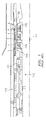
- FIG. 1A an environment is depicted of a system that may be applied in connection with a bearing compartment 101 of an engine.
- FIG. 1A there are six ring seal stages, denoted as stages 1 through 6, arranged about an engine centerline 102.
- a pair of adjacent ring seal stages e.g., stages 1 and 2 are bounded on either side by a pair of plates (e.g., plates 104 and 106) and a liner 108 located radially outward from the engine centerline 102.
- Also associated with the environment of FIG. 1A are two rotors; a so-called high rotor 110 and a low rotor 112.
- the two rotors 110 and 112 may rotate in the same direction or in opposite directions, with the same speed or with different speeds. Aspects of this disclosure are not limited to a co-rotating environment; for example, aspects of the disclosure may be applied in connection with a rotating structure arranged about a fixed/stationary structure.
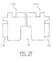
- FIG. 1B illustrates a pairing of any two adjacent stages (e.g., stages 1 and 2, or stages 3 and 4, or stages 5 and 6) of FIG. 1A.
- a cavity 152 for accommodating a retaining spring which loads these stages against the aforementioned plates (e.g., plates 104 and 106), causing contact pressure against them.
- Stages 1, 3 and 5 may contain higher levels of axial force, contact pressure and PV (contact pressure (P) multiplied by rubbing velocity (V)) levels compared to stages 2, 4 and 6. This is due to the additional air pressure loading imparted onto stages 1, 3 and 5.
- Stages 2, 4 and 6 also contain air pressure loading, however this pressure acts in the opposite direction so as to reduce the overall axial force, contact pressure and PV.
- the existing design of the six carbon ring elements contains a relief cut notch (e.g., notches 155 and 156 - see FIG. 1B ) on the inner diameter (ID) sealing face, which was set to avoid the adjacent seal plate radius edge (e.g., edge 132 of FIG. 1A) with radial eccentric overhang and a potential to cause a wear step in the carbon element.
- the need to avoid the seal plate radius edge only applies to stages 2, 4 and 6; however, the carbon element relief cut notch (e.g., notch 155 or notch 156) is provided on all 6 carbon ring stages 1-6 to maintain proper "fool-proofing" (e.g., to avoid improper assembly/installation).
- aspects of the disclosure are directed to a system comprising: a first seal that includes a notch configured to avoid an adjacent seal plate radius edge and a first protrusion, and a second seal that is notch-free with respect to an inner diameter sealing face and includes a second protrusion, wherein the first protrusion and the second protrusion are configured to at least partially overlap with one another in at least one of an axial direction or a radial direction with respect to an engine centerline.
- the first protrusion and the second protrusion are configured to at least partially overlap with one another in the axial direction and the radial direction.
- the system further comprises a spring located in a cavity formed between the first seal and the second seal.
- the first seal and the second seal are configured to provide an axial gap to accommodate a compression of the spring and a movement of the first seal and the second seal.
- the spring is a wave spring.
- the first seal and the second seal are configured to provide a radial gap that accommodates a movement of the first seal and the second seal.
- the first seal and the second seal are configured to provide a radius that accommodates a minimization in terms of stress.
- the first seal and the second seal are configured to be bound by a first plate and a second plate.
- the system further comprises a bearing compartment coupled to the first seal and the second seal.
- the first seal and the second seal are configured to be arranged about a first rotor and a second rotor.
- the first rotor rotates at a first speed and the second rotator rotates at a second speed that is different from the first speed.
- the first seal and the second seal are configured to be arranged about a first structure that rotates and a second structure that is stationary.
- the first protrusion and the second protrusion are configured such that if improperly assembled, the resulting assembly will require more axial space than is available between the plates, therefore providing assembly fool-proofing with respect to an orientation of the first seal and the second seal.
- connections are set forth between elements in the following description and in the drawings (the contents of which are included in this disclosure by way of reference). It is noted that these connections are general and, unless specified otherwise, may be direct or indirect and that this specification is not intended to be limiting in this respect.
- a coupling between two or more entities may refer to a direct connection or an indirect connection.
- An indirect connection may incorporate one or more intervening entities.
- apparatuses, systems and methods are described for providing a multi-stage inter shaft ring seal with additional "fool-proofing” measures (e.g., measure that prevent an improper assembly/installation) that enable contact pressure and PV(contact pressure multiplied by rubbing velocity) reduction on one or more stages, such as stages 1, 3, and 5.
- a ring seal geometry may contain/provide fool-proofing and overlapping "legs" that replace flat surfaces. These legs may meet one or more requirements, such as fool-proofing, gapping or physical space/geometry constraints, as well as meet all other ring seal application design requirements.
- the ring seal design will then also remove the inner diameter (ID) relief cut notch on stages 1, 3, and 5 as these stages may be unique compared to stages 2, 4, and 6. Stages 1, 3 and 5 may not require this notch because the adjacent seal plate geometry might not contain a radius edge to avoid radial eccentric overhang and a potential wear step. Stages 2, 4, and 6 may maintain the needed, proper ID relief cut notch. Accordingly, aspects of the disclosure may provide additional surface area and a resulting contact pressure/PV reduction on stages 1, 3, and 5 to mitigate carbon ring wear and failure.
- FIG. 2 is a side-sectional illustration of an exemplary gas turbine engine 210.
- the engine 210 includes a compressor section 212, a turbine section 214 and one or more engine hot sections.
- the engine hot sections may include, for example, a first engine hot section 216 configured as a combustor section and a second engine hot section 218 configured as an augmentor section.
- the compressor section 212, the first engine hot section 216, the turbine section 214 and the second engine hot section 218 may be sequentially aligned along an axial centerline 220 between a forward engine airflow inlet 222 and an aft engine airflow exhaust 224.
- the second engine hot section 218 may include a first (e.g., annular, radial inner) duct case 226, a second (e.g., annular, radial outer) duct case 228, and one or more hot section vanes 230.
- the engine 210 is illustrative. Aspects of the disclosure may be applied in connection with other engine types or configurations.
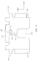
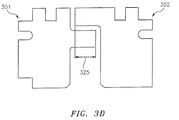
- a pair of seals in accordance with this disclosure are shown.
- a first of the seals is labeled with a reference character 301, and a second of the seals is labeled with a reference character 302.
- the seals 301 and 302 could serve as a substitute or replacement for one or more of the seals of FIGS. 1A-1B.
- one or more of the seal 301 could be used to replace one or more of the seals 1, 3, and 5, and one or more of the seal 302 could be used to replace one or more of the seals 2, 4, and 6.
- the seals 301 and 302 may include a number of distinguishing features which are denoted in FIG. 3 via reference characters 312-324. These features/reference characters 312-324 are described in further detail below.
- the reference character 312 refers to fool-proofing geometry "legs" or protrusions within a carbon ring seal design.
- the legs/protrusions 312 at least partially overlap with one another in at least one of an axial direction or a radial direction (with respect to an engine centerline (e.g., centerline 20 of FIG. 2 )). While the leg 312 associated with the seal 301 is shown as being of a greater size/dimension relative to the leg 312 associated with the seal 302, it is understood that they may be the same size/dimension or that the leg 312 associated with the seal 302 may be greater than the leg 312 associated with the seal 301 in terms of size/dimension. Furthermore, in some embodiments, the relative position of the legs 312 with respect to the seals 301 and 302 may be inverted relative to what is shown in FIG. 3 .
- the reference character 314 refers to fool-proofing (e.g., fool-proofing associated with the legs/protrusions 312 overlapping with one another) enabling a removal of an ID notch on stages 1, 3, and 5 (e.g., the notch 155 of FIG. 1B ), and a provisioning of additional contact area for PV and contact pressure reduction.
- the seal 301 may be referred to as being notch-free with respect to the ID sealing face.
- the reference character 316 refers to a cavity for accommodating a spring, e.g., a wave spring.
- the cavity 316 may be established to provide for spring optimization and may be selected based on prior use/experience.
- the cavity 316 may correspond to the cavity 152 of FIG. 1B .
- the reference character 318 refers to a radial gap that is selected to accommodate/allow a degree of carbon movement and avoid an interference with the radius.
- the reference character 320 refers to a notch for avoiding an adjacent seal plate radius edge while providing radial eccentricity, and may correspond to the notch 156 of FIG. 1B .
- the reference character 322 refers to a radius that is provided to accommodate a minimization/reduction in stress.
- the reference character 324 refers to axial gaps that are set/selected for allowing/enabling spring compression and carbon movement.
- the reference character 325 refers to axial amount of overlap between the seal members 301 and 302, so as to prevent improper assembly.
- FIG. 3A illustrates a minimum amount of overlap, which may be greater than or equal to the axial gap 324.
- FIG. 3B illustrates an embodiment of the invention wherein the amount of overlap is at its maximum, this maximum equal to the axial extent of the spring cavity 316 minus twice of the axial gap 324. Designs in between these latter two extreme locations are also possible.
- FIG. 3A illustrates the axial gap 324 between the two seal members located approximately at the middle of the spring cavity 316.
- FIGS. 3E-3F Two other embodiments of the invention are illustrated by FIGS. 3E-3F , showing axial shifts in the location of this gap.
- FIG. 3E shows the gap closest to seal element 301
- FIG. 3F shows the gap closest to seal element 302. Designs in between these latter two extreme locations are also possible.
- FIG. 3 The arrangement/orientation of the seals 301 and 302 as shown in FIG. 3 represents a proper assembly of the seals 301 and 302 with respect to one another.
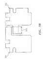
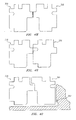
- FIGS. 4A-4O represent improper assemblies involving combinations of two of the seals 301 and 302.
- One or more of the features 312-330 described above provide for a fool-proof design as described below in connection with FIGS. 4A-4O , such that the improper assemblies will be visible or detectable prior to a full assembly of an engine.
- FIGS. 4A-4G , FIGS. 4I-4L , and FIG. 4N the improper assembly results in the spring not fitting.
- stages may experience a detectable amount of wear.
- the reference character 303 in FIG. 4O refers to a seal plate radius edge near the protruding inside edge of the non-notched seal 301. This location may correspond to the notch 132 and adjoining plate radius edge of FIG. 1A.
Landscapes
- Engineering & Computer Science (AREA)
- General Engineering & Computer Science (AREA)
- Mechanical Engineering (AREA)
- Chemical & Material Sciences (AREA)
- Combustion & Propulsion (AREA)
- Mechanical Sealing (AREA)
- Sealing Devices (AREA)
- Gasket Seals (AREA)
Applications Claiming Priority (1)
| Application Number | Priority Date | Filing Date | Title |
|---|---|---|---|
| US14/601,057 US9982604B2 (en) | 2015-01-20 | 2015-01-20 | Multi-stage inter shaft ring seal |
Publications (2)
| Publication Number | Publication Date |
|---|---|
| EP3048343A1 true EP3048343A1 (fr) | 2016-07-27 |
| EP3048343B1 EP3048343B1 (fr) | 2020-09-30 |
Family
ID=55182270
Family Applications (1)
| Application Number | Title | Priority Date | Filing Date |
|---|---|---|---|
| EP16152097.8A Not-in-force EP3048343B1 (fr) | 2015-01-20 | 2016-01-20 | Bague d'étanchéité d'arbre inter à plusieurs étages |
Country Status (2)
| Country | Link |
|---|---|
| US (1) | US9982604B2 (fr) |
| EP (1) | EP3048343B1 (fr) |
Cited By (4)
| Publication number | Priority date | Publication date | Assignee | Title |
|---|---|---|---|---|
| EP3354945A1 (fr) * | 2017-01-13 | 2018-08-01 | United Technologies Corporation | Agencement de joint d'étanchéité annulaire à deux pièces à constante vitesse |
| EP3415723A1 (fr) * | 2017-06-15 | 2018-12-19 | United Technologies Corporation | Agencement de joint à anneau |
| EP3428406A3 (fr) * | 2017-07-14 | 2019-02-20 | United Technologies Corporation | Agencement d'étanchéité à anneau avec installation infaillible |
| EP3543566A1 (fr) * | 2018-03-22 | 2019-09-25 | United Technologies Corporation | Joint de bague d'écartement incliné |
Families Citing this family (2)
| Publication number | Priority date | Publication date | Assignee | Title |
|---|---|---|---|---|
| US10415707B2 (en) * | 2016-06-30 | 2019-09-17 | General Electric Company | Face seal assembly and an associated method thereof |
| EP4336017B1 (fr) * | 2022-09-06 | 2025-10-29 | RTX Corporation | Bague d'étanchéité de piston |
Citations (5)
| Publication number | Priority date | Publication date | Assignee | Title |
|---|---|---|---|---|
| US2867458A (en) * | 1956-02-23 | 1959-01-06 | Sealol Corp | Shaft seal for gas turbines and the like |
| US3119623A (en) * | 1962-03-22 | 1964-01-28 | United Aircraft Corp | Thin land seal unit with seal type pressure regulator |
| US3271037A (en) * | 1963-04-01 | 1966-09-06 | Garlock Inc | Pressure-balanced segmental packing rings |
| FR2595430A1 (fr) * | 1986-03-10 | 1987-09-11 | Mitsubishi Heavy Ind Ltd | Dispositif d'etancheite pour machine a fluide rotative |
| US5518256A (en) * | 1992-04-08 | 1996-05-21 | Ksb Aktiengesellschaft | Floating-ring seal |
Family Cites Families (21)
| Publication number | Priority date | Publication date | Assignee | Title |
|---|---|---|---|---|
| US1544609A (en) * | 1922-10-31 | 1925-07-07 | Walter F Somes | Shaft packing for turbines and the like |
| US2379868A (en) | 1943-05-27 | 1945-07-10 | Curtis Pump Co | Pump seal construction |
| US2921805A (en) * | 1956-12-31 | 1960-01-19 | United Aircraft Corp | Pressure relieved ring seal |
| US3189357A (en) | 1962-06-22 | 1965-06-15 | Borg Warner | Annular seal with keyed sealing ring |
| GB1224234A (en) * | 1968-07-19 | 1971-03-03 | English Electric Co Ltd | Turbines |
| GB2044912B (en) | 1979-03-22 | 1983-02-23 | Rolls Royce | Gas turbine combustion chamber |
| US4415165A (en) | 1982-12-02 | 1983-11-15 | The United States Of America As Represented By The Secretary Of The Navy | Integral elastomeric/graphite dynamic face seal |
| JPS60147861U (ja) * | 1984-03-13 | 1985-10-01 | 三菱重工業株式会社 | 軸封装置 |
| US4754984A (en) | 1987-01-02 | 1988-07-05 | The United States Of America As Represented By The Secretary Of The Navy | Dual-seal-ring shaft seal |
| FR2644205B1 (fr) * | 1989-03-08 | 1991-05-03 | Snecma | Palier de turbomachine a joint d'etancheite integre |
| CA2056592A1 (fr) | 1990-12-21 | 1992-06-22 | Phillip D. Napoli | Chemise de chambre de combustion a refroidissement par gaine d'air a trous multiples avec demarreur a gaine d'air rainuree |
| US6125627A (en) | 1998-08-11 | 2000-10-03 | Allison Advanced Development Company | Method and apparatus for spraying fuel within a gas turbine engine |
| US6132168A (en) * | 1998-12-23 | 2000-10-17 | United Technologies Corporation | Balancing a pressure drop across ring seals in gas turbine engines |
| DE10346653A1 (de) | 2003-10-08 | 2005-06-09 | Kabelschlepp Gmbh | Kettenlasche, Kettenglied und Energieführungskette, sowie Zwischenstück für eine Energieführungskette, mit torsionsgekoppelten Verriegelungsmitteln zum Verbinden von Quersteg und Kettenlasche |
| US20050206088A1 (en) * | 2004-03-16 | 2005-09-22 | Anderson James H | Bearing seal with backup device |
| US8608175B2 (en) | 2005-10-28 | 2013-12-17 | United Technologies Corporation | Mechanical face seal stop pin |
| US8714557B2 (en) | 2005-10-28 | 2014-05-06 | United Technologies Corporation | Mechanical face seal housing with spring wall |
| US7687928B2 (en) | 2006-06-14 | 2010-03-30 | Smiths Aerospace, Llc | Dual-structured aircraft engine starter/generator |
| FR2930591B1 (fr) | 2008-04-24 | 2011-09-09 | Snecma | Optimisation du positionnement angulaire d'un distributeur de turbine en sortie d'une chambre de combustion de turbomachine |
| US20100192578A1 (en) | 2009-01-30 | 2010-08-05 | General Electric Company | System and method for suppressing combustion instability in a turbomachine |
| US9291066B2 (en) * | 2013-11-11 | 2016-03-22 | General Electric Company | Methods and systems for sealing a rotary machine using a segmented seal ring |
-
2015
- 2015-01-20 US US14/601,057 patent/US9982604B2/en active Active
-
2016
- 2016-01-20 EP EP16152097.8A patent/EP3048343B1/fr not_active Not-in-force
Patent Citations (5)
| Publication number | Priority date | Publication date | Assignee | Title |
|---|---|---|---|---|
| US2867458A (en) * | 1956-02-23 | 1959-01-06 | Sealol Corp | Shaft seal for gas turbines and the like |
| US3119623A (en) * | 1962-03-22 | 1964-01-28 | United Aircraft Corp | Thin land seal unit with seal type pressure regulator |
| US3271037A (en) * | 1963-04-01 | 1966-09-06 | Garlock Inc | Pressure-balanced segmental packing rings |
| FR2595430A1 (fr) * | 1986-03-10 | 1987-09-11 | Mitsubishi Heavy Ind Ltd | Dispositif d'etancheite pour machine a fluide rotative |
| US5518256A (en) * | 1992-04-08 | 1996-05-21 | Ksb Aktiengesellschaft | Floating-ring seal |
Cited By (7)
| Publication number | Priority date | Publication date | Assignee | Title |
|---|---|---|---|---|
| EP3354945A1 (fr) * | 2017-01-13 | 2018-08-01 | United Technologies Corporation | Agencement de joint d'étanchéité annulaire à deux pièces à constante vitesse |
| US10145255B2 (en) | 2017-01-13 | 2018-12-04 | United Technologies Corporation | Constant speed 2 piece ring seal arrangement |
| EP3415723A1 (fr) * | 2017-06-15 | 2018-12-19 | United Technologies Corporation | Agencement de joint à anneau |
| EP3428406A3 (fr) * | 2017-07-14 | 2019-02-20 | United Technologies Corporation | Agencement d'étanchéité à anneau avec installation infaillible |
| US10619742B2 (en) | 2017-07-14 | 2020-04-14 | United Technologies Corporation | Ring seal arrangement with installation foolproofing |
| EP3543566A1 (fr) * | 2018-03-22 | 2019-09-25 | United Technologies Corporation | Joint de bague d'écartement incliné |
| US11015715B2 (en) | 2018-03-22 | 2021-05-25 | Raytheon Technologies Corporation | Ramped spacer ring seal |
Also Published As
| Publication number | Publication date |
|---|---|
| US20160208710A1 (en) | 2016-07-21 |
| EP3048343B1 (fr) | 2020-09-30 |
| US9982604B2 (en) | 2018-05-29 |
Similar Documents
| Publication | Publication Date | Title |
|---|---|---|
| EP3048343B1 (fr) | Bague d'étanchéité d'arbre inter à plusieurs étages | |
| US8684695B2 (en) | Damper coverplate and sealing arrangement for turbine bucket shank | |
| US10309256B2 (en) | Non-linear bumper bearings | |
| EP2964901B1 (fr) | Ensemble joint comprenant un élément de joint à encoche destiné à être disposé entre un stator et un rotor | |
| US7618234B2 (en) | Hook ring segment for a compressor vane | |
| CN106536867B (zh) | 静叶、燃气轮机、分割环、静叶的改造方法以及分割环的改造方法 | |
| EP3118418B1 (fr) | Patin de joint avec lubrification par huile régulée | |
| EP2500520B1 (fr) | Amortisseur et agencement d'étanchéité pour aube de turbine | |
| EP2749795A1 (fr) | Dispositif d'étanchéité d'arbre et machine tournante comprenant ce dispositif | |
| US8353672B2 (en) | Turbine blade damper arrangement | |
| US10662793B2 (en) | Turbine wheel cover-plate mounted gas turbine interstage seal | |
| EP3094826B1 (fr) | Guide de ressort à bride pour un agencement d'étanchéité de face d'un moteur à turbine à gaz | |
| US20180372228A1 (en) | Hydrostatic non-contact seal with weight reduction pocket | |
| US9677669B2 (en) | Shaft seal device and rotary machine | |
| EP2639403A2 (fr) | Ensemble arbre pour moteur à turbine à gaz | |
| EP3048344B1 (fr) | Pré-cône de logement d'étanchéité | |
| EP2859257B1 (fr) | Plaque intermédiaire de bague d'étanchéité | |
| US9909452B2 (en) | Device for sealing between the coaxial shafts of a turbomachine | |
| US10655487B2 (en) | Pressure balanced secondary seal | |
| WO2020076301A1 (fr) | Joint d'étanchéité secondaire d'un ensemble joint d'étanchéité sans contact | |
| CN113167126B (zh) | 非接触密封组件中的副密封 | |
| JP2016037960A (ja) | シャフトシールシステム及び排ガスターボチャージャ | |
| CN108252754B (zh) | 自由动力涡轮 |
Legal Events
| Date | Code | Title | Description |
|---|---|---|---|
| PUAI | Public reference made under article 153(3) epc to a published international application that has entered the european phase |
Free format text: ORIGINAL CODE: 0009012 |
|
| AK | Designated contracting states |
Kind code of ref document: A1 Designated state(s): AL AT BE BG CH CY CZ DE DK EE ES FI FR GB GR HR HU IE IS IT LI LT LU LV MC MK MT NL NO PL PT RO RS SE SI SK SM TR |
|
| AX | Request for extension of the european patent |
Extension state: BA ME |
|
| RAP1 | Party data changed (applicant data changed or rights of an application transferred) |
Owner name: UNITED TECHNOLOGIES CORPORATION |
|
| STAA | Information on the status of an ep patent application or granted ep patent |
Free format text: STATUS: REQUEST FOR EXAMINATION WAS MADE |
|
| 17P | Request for examination filed |
Effective date: 20170127 |
|
| RBV | Designated contracting states (corrected) |
Designated state(s): AL AT BE BG CH CY CZ DE DK EE ES FI FR GB GR HR HU IE IS IT LI LT LU LV MC MK MT NL NO PL PT RO RS SE SI SK SM TR |
|
| STAA | Information on the status of an ep patent application or granted ep patent |
Free format text: STATUS: EXAMINATION IS IN PROGRESS |
|
| RIC1 | Information provided on ipc code assigned before grant |
Ipc: F01D 11/00 20060101ALI20180605BHEP Ipc: F16J 15/3268 20160101ALI20180605BHEP Ipc: F02C 7/28 20060101ALI20180605BHEP Ipc: F01D 25/18 20060101ALI20180605BHEP Ipc: F16J 15/44 20060101AFI20180605BHEP Ipc: F16J 15/30 20060101ALI20180605BHEP |
|
| 17Q | First examination report despatched |
Effective date: 20180625 |
|
| GRAP | Despatch of communication of intention to grant a patent |
Free format text: ORIGINAL CODE: EPIDOSNIGR1 |
|
| STAA | Information on the status of an ep patent application or granted ep patent |
Free format text: STATUS: GRANT OF PATENT IS INTENDED |
|
| INTG | Intention to grant announced |
Effective date: 20200428 |
|
| GRAS | Grant fee paid |
Free format text: ORIGINAL CODE: EPIDOSNIGR3 |
|
| GRAA | (expected) grant |
Free format text: ORIGINAL CODE: 0009210 |
|
| STAA | Information on the status of an ep patent application or granted ep patent |
Free format text: STATUS: THE PATENT HAS BEEN GRANTED |
|
| AK | Designated contracting states |
Kind code of ref document: B1 Designated state(s): AL AT BE BG CH CY CZ DE DK EE ES FI FR GB GR HR HU IE IS IT LI LT LU LV MC MK MT NL NO PL PT RO RS SE SI SK SM TR |
|
| REG | Reference to a national code |
Ref country code: GB Ref legal event code: FG4D Ref country code: CH Ref legal event code: EP |
|
| REG | Reference to a national code |
Ref country code: AT Ref legal event code: REF Ref document number: 1319129 Country of ref document: AT Kind code of ref document: T Effective date: 20201015 Ref country code: DE Ref legal event code: R096 Ref document number: 602016044809 Country of ref document: DE |
|
| REG | Reference to a national code |
Ref country code: IE Ref legal event code: FG4D |
|
| PG25 | Lapsed in a contracting state [announced via postgrant information from national office to epo] |
Ref country code: FI Free format text: LAPSE BECAUSE OF FAILURE TO SUBMIT A TRANSLATION OF THE DESCRIPTION OR TO PAY THE FEE WITHIN THE PRESCRIBED TIME-LIMIT Effective date: 20200930 Ref country code: GR Free format text: LAPSE BECAUSE OF FAILURE TO SUBMIT A TRANSLATION OF THE DESCRIPTION OR TO PAY THE FEE WITHIN THE PRESCRIBED TIME-LIMIT Effective date: 20201231 Ref country code: HR Free format text: LAPSE BECAUSE OF FAILURE TO SUBMIT A TRANSLATION OF THE DESCRIPTION OR TO PAY THE FEE WITHIN THE PRESCRIBED TIME-LIMIT Effective date: 20200930 Ref country code: NO Free format text: LAPSE BECAUSE OF FAILURE TO SUBMIT A TRANSLATION OF THE DESCRIPTION OR TO PAY THE FEE WITHIN THE PRESCRIBED TIME-LIMIT Effective date: 20201230 Ref country code: BG Free format text: LAPSE BECAUSE OF FAILURE TO SUBMIT A TRANSLATION OF THE DESCRIPTION OR TO PAY THE FEE WITHIN THE PRESCRIBED TIME-LIMIT Effective date: 20201230 Ref country code: SE Free format text: LAPSE BECAUSE OF FAILURE TO SUBMIT A TRANSLATION OF THE DESCRIPTION OR TO PAY THE FEE WITHIN THE PRESCRIBED TIME-LIMIT Effective date: 20200930 |
|
| REG | Reference to a national code |
Ref country code: AT Ref legal event code: MK05 Ref document number: 1319129 Country of ref document: AT Kind code of ref document: T Effective date: 20200930 |
|
| PG25 | Lapsed in a contracting state [announced via postgrant information from national office to epo] |
Ref country code: RS Free format text: LAPSE BECAUSE OF FAILURE TO SUBMIT A TRANSLATION OF THE DESCRIPTION OR TO PAY THE FEE WITHIN THE PRESCRIBED TIME-LIMIT Effective date: 20200930 Ref country code: LV Free format text: LAPSE BECAUSE OF FAILURE TO SUBMIT A TRANSLATION OF THE DESCRIPTION OR TO PAY THE FEE WITHIN THE PRESCRIBED TIME-LIMIT Effective date: 20200930 |
|
| REG | Reference to a national code |
Ref country code: NL Ref legal event code: MP Effective date: 20200930 |
|
| RAP2 | Party data changed (patent owner data changed or rights of a patent transferred) |
Owner name: RAYTHEON TECHNOLOGIES CORPORATION |
|
| REG | Reference to a national code |
Ref country code: LT Ref legal event code: MG4D |
|
| PG25 | Lapsed in a contracting state [announced via postgrant information from national office to epo] |
Ref country code: EE Free format text: LAPSE BECAUSE OF FAILURE TO SUBMIT A TRANSLATION OF THE DESCRIPTION OR TO PAY THE FEE WITHIN THE PRESCRIBED TIME-LIMIT Effective date: 20200930 Ref country code: PT Free format text: LAPSE BECAUSE OF FAILURE TO SUBMIT A TRANSLATION OF THE DESCRIPTION OR TO PAY THE FEE WITHIN THE PRESCRIBED TIME-LIMIT Effective date: 20210201 Ref country code: SM Free format text: LAPSE BECAUSE OF FAILURE TO SUBMIT A TRANSLATION OF THE DESCRIPTION OR TO PAY THE FEE WITHIN THE PRESCRIBED TIME-LIMIT Effective date: 20200930 Ref country code: RO Free format text: LAPSE BECAUSE OF FAILURE TO SUBMIT A TRANSLATION OF THE DESCRIPTION OR TO PAY THE FEE WITHIN THE PRESCRIBED TIME-LIMIT Effective date: 20200930 Ref country code: LT Free format text: LAPSE BECAUSE OF FAILURE TO SUBMIT A TRANSLATION OF THE DESCRIPTION OR TO PAY THE FEE WITHIN THE PRESCRIBED TIME-LIMIT Effective date: 20200930 Ref country code: NL Free format text: LAPSE BECAUSE OF FAILURE TO SUBMIT A TRANSLATION OF THE DESCRIPTION OR TO PAY THE FEE WITHIN THE PRESCRIBED TIME-LIMIT Effective date: 20200930 Ref country code: CZ Free format text: LAPSE BECAUSE OF FAILURE TO SUBMIT A TRANSLATION OF THE DESCRIPTION OR TO PAY THE FEE WITHIN THE PRESCRIBED TIME-LIMIT Effective date: 20200930 |
|
| PG25 | Lapsed in a contracting state [announced via postgrant information from national office to epo] |
Ref country code: AT Free format text: LAPSE BECAUSE OF FAILURE TO SUBMIT A TRANSLATION OF THE DESCRIPTION OR TO PAY THE FEE WITHIN THE PRESCRIBED TIME-LIMIT Effective date: 20200930 Ref country code: AL Free format text: LAPSE BECAUSE OF FAILURE TO SUBMIT A TRANSLATION OF THE DESCRIPTION OR TO PAY THE FEE WITHIN THE PRESCRIBED TIME-LIMIT Effective date: 20200930 Ref country code: ES Free format text: LAPSE BECAUSE OF FAILURE TO SUBMIT A TRANSLATION OF THE DESCRIPTION OR TO PAY THE FEE WITHIN THE PRESCRIBED TIME-LIMIT Effective date: 20200930 Ref country code: IS Free format text: LAPSE BECAUSE OF FAILURE TO SUBMIT A TRANSLATION OF THE DESCRIPTION OR TO PAY THE FEE WITHIN THE PRESCRIBED TIME-LIMIT Effective date: 20210130 Ref country code: PL Free format text: LAPSE BECAUSE OF FAILURE TO SUBMIT A TRANSLATION OF THE DESCRIPTION OR TO PAY THE FEE WITHIN THE PRESCRIBED TIME-LIMIT Effective date: 20200930 |
|
| PG25 | Lapsed in a contracting state [announced via postgrant information from national office to epo] |
Ref country code: SK Free format text: LAPSE BECAUSE OF FAILURE TO SUBMIT A TRANSLATION OF THE DESCRIPTION OR TO PAY THE FEE WITHIN THE PRESCRIBED TIME-LIMIT Effective date: 20200930 |
|
| REG | Reference to a national code |
Ref country code: DE Ref legal event code: R097 Ref document number: 602016044809 Country of ref document: DE |
|
| PLBE | No opposition filed within time limit |
Free format text: ORIGINAL CODE: 0009261 |
|
| STAA | Information on the status of an ep patent application or granted ep patent |
Free format text: STATUS: NO OPPOSITION FILED WITHIN TIME LIMIT |
|
| PG25 | Lapsed in a contracting state [announced via postgrant information from national office to epo] |
Ref country code: DK Free format text: LAPSE BECAUSE OF FAILURE TO SUBMIT A TRANSLATION OF THE DESCRIPTION OR TO PAY THE FEE WITHIN THE PRESCRIBED TIME-LIMIT Effective date: 20200930 Ref country code: MC Free format text: LAPSE BECAUSE OF FAILURE TO SUBMIT A TRANSLATION OF THE DESCRIPTION OR TO PAY THE FEE WITHIN THE PRESCRIBED TIME-LIMIT Effective date: 20200930 |
|
| REG | Reference to a national code |
Ref country code: CH Ref legal event code: PL |
|
| 26N | No opposition filed |
Effective date: 20210701 |
|
| PG25 | Lapsed in a contracting state [announced via postgrant information from national office to epo] |
Ref country code: LU Free format text: LAPSE BECAUSE OF NON-PAYMENT OF DUE FEES Effective date: 20210120 |
|
| REG | Reference to a national code |
Ref country code: BE Ref legal event code: MM Effective date: 20210131 |
|
| PG25 | Lapsed in a contracting state [announced via postgrant information from national office to epo] |
Ref country code: IT Free format text: LAPSE BECAUSE OF FAILURE TO SUBMIT A TRANSLATION OF THE DESCRIPTION OR TO PAY THE FEE WITHIN THE PRESCRIBED TIME-LIMIT Effective date: 20200930 |
|
| PG25 | Lapsed in a contracting state [announced via postgrant information from national office to epo] |
Ref country code: LI Free format text: LAPSE BECAUSE OF NON-PAYMENT OF DUE FEES Effective date: 20210131 Ref country code: SI Free format text: LAPSE BECAUSE OF FAILURE TO SUBMIT A TRANSLATION OF THE DESCRIPTION OR TO PAY THE FEE WITHIN THE PRESCRIBED TIME-LIMIT Effective date: 20200930 Ref country code: CH Free format text: LAPSE BECAUSE OF NON-PAYMENT OF DUE FEES Effective date: 20210131 |
|
| PG25 | Lapsed in a contracting state [announced via postgrant information from national office to epo] |
Ref country code: IE Free format text: LAPSE BECAUSE OF NON-PAYMENT OF DUE FEES Effective date: 20210120 |
|
| PG25 | Lapsed in a contracting state [announced via postgrant information from national office to epo] |
Ref country code: IS Free format text: LAPSE BECAUSE OF FAILURE TO SUBMIT A TRANSLATION OF THE DESCRIPTION OR TO PAY THE FEE WITHIN THE PRESCRIBED TIME-LIMIT Effective date: 20210130 |
|
| PG25 | Lapsed in a contracting state [announced via postgrant information from national office to epo] |
Ref country code: BE Free format text: LAPSE BECAUSE OF NON-PAYMENT OF DUE FEES Effective date: 20210131 |
|
| PG25 | Lapsed in a contracting state [announced via postgrant information from national office to epo] |
Ref country code: HU Free format text: LAPSE BECAUSE OF FAILURE TO SUBMIT A TRANSLATION OF THE DESCRIPTION OR TO PAY THE FEE WITHIN THE PRESCRIBED TIME-LIMIT; INVALID AB INITIO Effective date: 20160120 |
|
| P01 | Opt-out of the competence of the unified patent court (upc) registered |
Effective date: 20230520 |
|
| PG25 | Lapsed in a contracting state [announced via postgrant information from national office to epo] |
Ref country code: CY Free format text: LAPSE BECAUSE OF FAILURE TO SUBMIT A TRANSLATION OF THE DESCRIPTION OR TO PAY THE FEE WITHIN THE PRESCRIBED TIME-LIMIT Effective date: 20200930 |
|
| PGFP | Annual fee paid to national office [announced via postgrant information from national office to epo] |
Ref country code: GB Payment date: 20231219 Year of fee payment: 9 |
|
| PGFP | Annual fee paid to national office [announced via postgrant information from national office to epo] |
Ref country code: FR Payment date: 20231219 Year of fee payment: 9 |
|
| PG25 | Lapsed in a contracting state [announced via postgrant information from national office to epo] |
Ref country code: MK Free format text: LAPSE BECAUSE OF FAILURE TO SUBMIT A TRANSLATION OF THE DESCRIPTION OR TO PAY THE FEE WITHIN THE PRESCRIBED TIME-LIMIT Effective date: 20200930 |
|
| PGFP | Annual fee paid to national office [announced via postgrant information from national office to epo] |
Ref country code: DE Payment date: 20231219 Year of fee payment: 9 |
|
| PG25 | Lapsed in a contracting state [announced via postgrant information from national office to epo] |
Ref country code: TR Free format text: LAPSE BECAUSE OF FAILURE TO SUBMIT A TRANSLATION OF THE DESCRIPTION OR TO PAY THE FEE WITHIN THE PRESCRIBED TIME-LIMIT Effective date: 20200930 |
|
| PG25 | Lapsed in a contracting state [announced via postgrant information from national office to epo] |
Ref country code: MT Free format text: LAPSE BECAUSE OF FAILURE TO SUBMIT A TRANSLATION OF THE DESCRIPTION OR TO PAY THE FEE WITHIN THE PRESCRIBED TIME-LIMIT Effective date: 20200930 |
|
| REG | Reference to a national code |
Ref country code: DE Ref legal event code: R119 Ref document number: 602016044809 Country of ref document: DE |
|
| GBPC | Gb: european patent ceased through non-payment of renewal fee |
Effective date: 20250120 |
|
| PG25 | Lapsed in a contracting state [announced via postgrant information from national office to epo] |
Ref country code: DE Free format text: LAPSE BECAUSE OF NON-PAYMENT OF DUE FEES Effective date: 20250801 |
|
| PG25 | Lapsed in a contracting state [announced via postgrant information from national office to epo] |
Ref country code: GB Free format text: LAPSE BECAUSE OF NON-PAYMENT OF DUE FEES Effective date: 20250120 |
|
| PG25 | Lapsed in a contracting state [announced via postgrant information from national office to epo] |
Ref country code: FR Free format text: LAPSE BECAUSE OF NON-PAYMENT OF DUE FEES Effective date: 20250131 |