EP3048356A1 - Commande de lubrification par surveillance de courant de moteur de pompe - Google Patents
Commande de lubrification par surveillance de courant de moteur de pompe Download PDFInfo
- Publication number
- EP3048356A1 EP3048356A1 EP16151006.0A EP16151006A EP3048356A1 EP 3048356 A1 EP3048356 A1 EP 3048356A1 EP 16151006 A EP16151006 A EP 16151006A EP 3048356 A1 EP3048356 A1 EP 3048356A1
- Authority
- EP
- European Patent Office
- Prior art keywords
- lubricant
- lubrication system
- motor
- positive displacement
- displacement pump
- Prior art date
- Legal status (The legal status is an assumption and is not a legal conclusion. Google has not performed a legal analysis and makes no representation as to the accuracy of the status listed.)
- Granted
Links
Images


Classifications
-
- F—MECHANICAL ENGINEERING; LIGHTING; HEATING; WEAPONS; BLASTING
- F16—ENGINEERING ELEMENTS AND UNITS; GENERAL MEASURES FOR PRODUCING AND MAINTAINING EFFECTIVE FUNCTIONING OF MACHINES OR INSTALLATIONS; THERMAL INSULATION IN GENERAL
- F16N—LUBRICATING
- F16N29/00—Special means in lubricating arrangements or systems providing for the indication or detection of undesired conditions; Use of devices responsive to conditions in lubricating arrangements or systems
- F16N29/02—Special means in lubricating arrangements or systems providing for the indication or detection of undesired conditions; Use of devices responsive to conditions in lubricating arrangements or systems for influencing the supply of lubricant
-
- F—MECHANICAL ENGINEERING; LIGHTING; HEATING; WEAPONS; BLASTING
- F16—ENGINEERING ELEMENTS AND UNITS; GENERAL MEASURES FOR PRODUCING AND MAINTAINING EFFECTIVE FUNCTIONING OF MACHINES OR INSTALLATIONS; THERMAL INSULATION IN GENERAL
- F16N—LUBRICATING
- F16N7/00—Arrangements for supplying oil or unspecified lubricant from a stationary reservoir or the equivalent in or on the machine or member to be lubricated
- F16N7/38—Arrangements for supplying oil or unspecified lubricant from a stationary reservoir or the equivalent in or on the machine or member to be lubricated with a separate pump; Central lubrication systems
-
- F—MECHANICAL ENGINEERING; LIGHTING; HEATING; WEAPONS; BLASTING
- F04—POSITIVE - DISPLACEMENT MACHINES FOR LIQUIDS; PUMPS FOR LIQUIDS OR ELASTIC FLUIDS
- F04B—POSITIVE-DISPLACEMENT MACHINES FOR LIQUIDS; PUMPS
- F04B49/00—Control, e.g. of pump delivery, or pump pressure of, or safety measures for, machines, pumps, or pumping installations, not otherwise provided for, or of interest apart from, groups F04B1/00 - F04B47/00
- F04B49/06—Control using electricity
- F04B49/065—Control using electricity and making use of computers
-
- F—MECHANICAL ENGINEERING; LIGHTING; HEATING; WEAPONS; BLASTING
- F16—ENGINEERING ELEMENTS AND UNITS; GENERAL MEASURES FOR PRODUCING AND MAINTAINING EFFECTIVE FUNCTIONING OF MACHINES OR INSTALLATIONS; THERMAL INSULATION IN GENERAL
- F16N—LUBRICATING
- F16N13/00—Lubricating-pumps
-
- F—MECHANICAL ENGINEERING; LIGHTING; HEATING; WEAPONS; BLASTING
- F16—ENGINEERING ELEMENTS AND UNITS; GENERAL MEASURES FOR PRODUCING AND MAINTAINING EFFECTIVE FUNCTIONING OF MACHINES OR INSTALLATIONS; THERMAL INSULATION IN GENERAL
- F16N—LUBRICATING
- F16N13/00—Lubricating-pumps
- F16N13/02—Lubricating-pumps with reciprocating piston
- F16N13/06—Actuation of lubricating-pumps
-
- F—MECHANICAL ENGINEERING; LIGHTING; HEATING; WEAPONS; BLASTING
- F16—ENGINEERING ELEMENTS AND UNITS; GENERAL MEASURES FOR PRODUCING AND MAINTAINING EFFECTIVE FUNCTIONING OF MACHINES OR INSTALLATIONS; THERMAL INSULATION IN GENERAL
- F16N—LUBRICATING
- F16N13/00—Lubricating-pumps
- F16N13/22—Lubricating-pumps with distributing equipment
-
- F—MECHANICAL ENGINEERING; LIGHTING; HEATING; WEAPONS; BLASTING
- F16—ENGINEERING ELEMENTS AND UNITS; GENERAL MEASURES FOR PRODUCING AND MAINTAINING EFFECTIVE FUNCTIONING OF MACHINES OR INSTALLATIONS; THERMAL INSULATION IN GENERAL
- F16N—LUBRICATING
- F16N19/00—Lubricant containers for use in lubricators or lubrication systems
-
- F—MECHANICAL ENGINEERING; LIGHTING; HEATING; WEAPONS; BLASTING
- F16—ENGINEERING ELEMENTS AND UNITS; GENERAL MEASURES FOR PRODUCING AND MAINTAINING EFFECTIVE FUNCTIONING OF MACHINES OR INSTALLATIONS; THERMAL INSULATION IN GENERAL
- F16N—LUBRICATING
- F16N21/00—Conduits; Junctions; Fittings for lubrication apertures
-
- F—MECHANICAL ENGINEERING; LIGHTING; HEATING; WEAPONS; BLASTING
- F16—ENGINEERING ELEMENTS AND UNITS; GENERAL MEASURES FOR PRODUCING AND MAINTAINING EFFECTIVE FUNCTIONING OF MACHINES OR INSTALLATIONS; THERMAL INSULATION IN GENERAL
- F16N—LUBRICATING
- F16N29/00—Special means in lubricating arrangements or systems providing for the indication or detection of undesired conditions; Use of devices responsive to conditions in lubricating arrangements or systems
-
- F—MECHANICAL ENGINEERING; LIGHTING; HEATING; WEAPONS; BLASTING
- F16—ENGINEERING ELEMENTS AND UNITS; GENERAL MEASURES FOR PRODUCING AND MAINTAINING EFFECTIVE FUNCTIONING OF MACHINES OR INSTALLATIONS; THERMAL INSULATION IN GENERAL
- F16N—LUBRICATING
- F16N13/00—Lubricating-pumps
- F16N13/02—Lubricating-pumps with reciprocating piston
- F16N13/06—Actuation of lubricating-pumps
- F16N2013/063—Actuation of lubricating-pumps with electrical drive
-
- F—MECHANICAL ENGINEERING; LIGHTING; HEATING; WEAPONS; BLASTING
- F16—ENGINEERING ELEMENTS AND UNITS; GENERAL MEASURES FOR PRODUCING AND MAINTAINING EFFECTIVE FUNCTIONING OF MACHINES OR INSTALLATIONS; THERMAL INSULATION IN GENERAL
- F16N—LUBRICATING
- F16N2250/00—Measuring
- F16N2250/40—Flow
-
- F—MECHANICAL ENGINEERING; LIGHTING; HEATING; WEAPONS; BLASTING
- F16—ENGINEERING ELEMENTS AND UNITS; GENERAL MEASURES FOR PRODUCING AND MAINTAINING EFFECTIVE FUNCTIONING OF MACHINES OR INSTALLATIONS; THERMAL INSULATION IN GENERAL
- F16N—LUBRICATING
- F16N2270/00—Controlling
- F16N2270/20—Amount of lubricant
Definitions
- the present invention concerns a lubrication system comprising a control unit that is arranged to determine the amount of lubricant that is dispensed from the lubricant system when it is in use.
- the present invention also concerns a method and a computer program product for determining the amount of lubricant that is dispensed from such a lubricant system when it is in use.
- Lubrication systems perform the task of supplying individual lubrication points or a group of lubrication points, such as at least one part of a bearing, joint, gear, and/or any other part(s) of one or more machines with a varying or non-varying amount of exactly metered lubricant to ensure that no lubrication point is over- or under-lubricated.
- Over- or under-lubrication can namely negatively influence a machine component's service life and may result in machine breakdown.
- a lubricant is usually fed to one or more lubrication points using a motor-driven feed pump, such as a piston pump, which ensures that lubricant is dispensed in the required amount.
- a lubrication system is usually monitored and controlled using components such as lubricant level sensors and switches, pressure switches/gauges and transmitters, flow meters, volumetric meters, oil-streak sensors, dirt indicators, differential pressure switches, motion displays, piston detectors, moisture sensors and temperature measuring devices.
- US patent 8 528 782 discloses a grease gun that includes a housing, a motor positioned within the housing, a pump assembly coupled to and driven by the motor, and a chamber supported by the housing in fluid communication with the pump assembly.
- the chamber is configured to store a liquid.
- the grease gun also includes an outlet in fluid communication with the chamber and a measurement system operable to measure an amount of liquid being dispensed through the outlet.
- the measurement system monitors a change in current of the motor over a cycle of the pump assembly, compares the change in current to a predetermined value, and, if the change in current is greater than the predetermined value, increases a pump cycle counter to indicate that liquid was dispensed. If the change is current is less than the predetermined value, it is inferred that there is an air bubble in the pump assembly or that the chamber is empty.
- a Hall proximity sensor is used for determining when the piston cycle is completed.
- An object of the invention is to provide an improved lubrication system comprising a motor, such as a DC electric motor, a positive displacement pump driven by the motor, a lubricant container in fluid communication with the positive displacement pump and at least one lubricant outlet in fluid communication with the lubricant container.
- the positive displacement pump is arranged to carry out at least one discharge stroke to dispense lubricant from the at least one lubricant outlet when the lubrication system is in use.
- the lubrication system also comprises a control unit that is arranged to determine the amount of lubricant that is dispensed from the lubricant container via the at least one lubricant outlet when the lubrication system is in use
- a lubrication system comprising a control unit that is arranged to monitor current supplied to the motor so as to obtain a motor current signal, and to determine the number of the discharge strokes from the motor current signal. No additional equipment is therefore necessary to count discharge strokes. The number of discharge strokes can be directly obtained from the motor current signal. If the number of discharge strokes is known, and if the amount of lubricant dispensed from each lubricant outlet with each discharge stroke is known or can be determined, then the volume or weight output of lubricant from the lubrication system can consequently be determined and the lubrication system can thereby be controlled to dispense a desired amount of lubricant when necessary.
- components such as pressure switches/gauges and transmitters, flow meters, volumetric meters, differential pressure switches and piston detectors are not required to monitor and control the lubrication system, thereby reducing the cost and complexity of the control unit needed for monitoring the lubrication system. Furthermore, it is possible to determine from the current shape minimum/maximum relationship that the output is lubricant and not air.
- a lubrication system according to the present invention may be used for any industrial application to provide the appropriate lubrication quantity at the correct intervals, thereby minimizing friction and wear and optimizing component and machinery service life.
- the lubrication system provides proper, precise lubricant replenishment to all required points, enabling significant savings in repair and spare costs, increased machine reliability, savings in lubricant costs due to accurate timing and dosing of lubricants, fewer shutdowns and production losses, reduced environmental impact and greater safety for workers.
- control unit is arranged to convert the motor current signal to pulses and count the number of the discharge strokes by counting the pulses.
- control unit is arranged to determine the output pressure of the positive displacement pump from the motor current signal.
- the present invention also concerns a method for determining the amount of lubricant that is dispensed from a lubrication system, such as a lubrication system according to any embodiment of the present invention.
- the lubrication system comprises a motor, a positive displacement pump driven by the motor, a lubricant container in fluid communication with the positive displacement pump and at least one lubricant outlet in fluid communication with the lubricant container.
- the positive displacement pump is arranged to carry out at least one discharge stroke to dispense lubricant from the at least one lubricant outlet when the lubrication system is in use.
- the lubrication system also comprises a control unit that is arranged to determine the amount of lubricant that is dispensed from the lubricant container via the at least one lubricant outlet when the lubrication system is in use.
- the method comprises the steps of monitoring current supplied to the motor so as to obtain a motor current signal, and determining the number of the discharge strokes from the motor current signal.
- the method comprises the steps of converting the motor current signal to pulses and counting the number of the discharge strokes by counting the pulses.
- the method comprises the step of determining the output pressure of the positive displacement pump from the motor current signal.
- the present invention further concerns a computer program product that comprises a computer program containing computer program code means arranged to cause a computer or a processor to execute the steps of a method according to any of the embodiments of the present invention, stored on a computer-readable medium or a carrier wave.
- a lubrication system, a method or a computer program product according to the present invention may be used to lubricate at least a part of one of the following: a ball bearing, a roller bearing, a needle bearing, a tapered roller bearing, a spherical roller bearing, a toroidal roller bearing, a ball thrust bearing, a roller thrust bearing, a tapered roller thrust bearing, a wheel bearing, a hub bearing unit, a slewing bearing, a ball screw, or any component for an application in which it is subjected to alternating Hertzian stresses, such as rolling contact or combined rolling and sliding.
- At least one part of gear teeth, a camshaft, a fastener, a pin, an automotive clutch plate, a tool, or a die may be lubricated.
- the lubrication system, a method or a computer program product may be used in automotive, aerospace, wind, marine, printing, construction, metal producing applications, and/or any machine applications.
- lubrication system, a method or a computer program product may be used to lubricate any part of a paper machine, continuous caster, fan, blower, crushing and/or grinding mills, an industrial transmission, conveyor, a motor or pump.
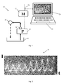
- Figure 1 shows a lubrication system 10 comprising a motor 12, a positive displacement pump 14 driven by the motor 12, a lubricant container 16 in fluid communication with the positive displacement pump 14 and a lubricant outlet 18 in fluid communication with the lubricant container 16.
- the motor 12 is a DC electric motor.
- the fluid container 16 can be arranged to store lubricant directly or to receive lubricant-filled cartridges.
- the positive displacement pump 14 is arranged to carry out at least one discharge stroke to dispense lubricant from the lubricant outlet 16 when the lubrication system 10 is in use.
- the lubricant dispensed from the lubricant outlet 16 lubricates a lubricant point 20. In circulation lubrication systems, lubricant may then be returned to the lubricant container 16 although this will not be the case in total loss lubrication systems.
- the lubrication system 10 comprises a control unit 22 that is arranged to determine the amount of lubricant that is dispensed from the lubricant container 16 via the lubricant outlet 16 when the lubrication system 10 is in use. It should be noted that the control unit 22 is typically an embedded controller inside a pump (14) instead of an external computer as illustrated in figure 1 .
- the positive displacement pump 14 may be a piston pump, such as an axial or a radial piston pump.
- a piston pump usually comprises reciprocating element, such as a piston which is arranged to reciprocate in a chamber in the pump head.
- the lubricant inlet and - outlet lines are joined to the piston chamber.
- the inlet valve allows flow from the inlet line to the piston chamber, but not in the reverse direction.
- the outlet valve allows flow from the chamber to the outlet line, but not in reverse.
- the motor 12 that drives the piston pump repeatedly moves the piston back and forth in the piston chamber, causing the volume of the chamber to repeatedly become smaller and larger. When the piston moves out, a vacuum is created.
- a single-piston pump delivers liquid to a lubricant outlet only during the discharge stroke. If the piston's suction and discharge strokes occur at the same speed and lubricant is metered out half the time the pump is working, then the overall metering rate averaged over time equals half the average flow rate during the discharge stroke.
- Some single-piston pumps may have a constant slow piston motion for discharge and a quick retract motion for refilling the pump head. In such cases, the overall metering rate is practically equal to the pumping rate during the discharge stroke.
- the lubrication system 10 comprises a control unit 22 that is arranged to monitor current 24 supplied to the motor 12, for example by measuring the output of a motor driver, so as to obtain a motor current signal 26, and to determine the number of the discharge strokes from the motor current signal 26.
- a motor current signal 26 can be displayed on display means, such as a computer monitor or an oscilloscope screen.
- a display means may also be used to display the amount of lubricant (in volume or weight) dispensed during each discharge stroke of the positive displacement pump or the amount of lubricant that has already been dispensed.
- Data and/or one or more control signals may optionally be sent to the motor 12 and/or to a lubrication system controller to provide information about the amount of lubricant that has been dispensed and/or the amount of lubricant that is being dispensed. It can be determined whether the strokes of the positive displacement pump 14 are pumping lubricant or air and then the amount of lubricant can be controlled by counting the strokes.
- a lubrication system 10 may comprise additional conventional components such as a lubricant filters or a cooling system. Additionally, a lubrication system 10 according to the present invention may be used to lubricate any number of lubrication points 20 on one or more machines. Furthermore, a control unit 22 need not necessarily be located in the same location as a lubrication system 10. A control unit 22 may namely be arranged at any local or remote location and it be arranged to communicate with one or more lubrication systems 10 according to the present invention by any suitable wired or wireless means. A control unit 22 need not necessarily constitute a single unit, but may comprise a plurality of separate components located at one or more locations.
- control unit 22 is a computer comprising a display means for displaying motor current signals 26 to a user.
- Lubrication system commands may be inputted via the control unit 22 and data may be displayed and/or be sent to a database and/or another display means and/or another user.
- a control system 22 may be arranged to issue and/or send an alarm signal on analysis of motor current signals 26.
- Figure 2 shows a typical motor current signal 26 obtained when the motor 12 of a lubrication system 10 according to an embodiment of the invention is running.
- the variable load on the reciprocating element of the positive displacement pump 14, such as the piston of a piston pump, causes a cyclic current.
- the current reaches is minimum value.
- the current reaches is maximum value.
- the maximum current measured may increase with time, as shown in figure 2 , if the output pressure of the positive displacement pump 14 increases with time.
- the minimum current indicates friction in motor gear and the movement of a follower plate in a lubricant container. It's magnitude may be dependent on the temperature or the type of lubricant used in the lubrication system 10.
- the peak to peak current of a cycle represents the force needed to move the reciprocating element of the positive displacement pump 14.
- a piston spring force may cause an offset in the current.
- the current signal may be measured for P/I conversion at a 0 bar level, when lubricant is pumped freely (0 bar current).
- the peak to peak current may be used for calculating the output pressure.
- a control unit 22 is arranged to convert a motor current signal 26 to pulses 28, by thresholding the motor current signal 26 for example, and to count the number of the discharge strokes of the positive displacement pump 14 by counting the pulses 28.
- the motor current is measured using various pump stop pressures. By counting the current pulses 28, the output volume of the positive displacement pump 14 can be measured, and the lubrication can thereby be controlled.
- Figure 3 shows a motor current signal 26 from a lubrication system 10 and the pulses 28 obtained therefrom.
- the lubrication is controlled using output pressure. Pressurizing of lubricant, i.e. pumping stops when the motor current 24 reaches a predetermined set stop level, such as a pre-programmed pressure limit, such as a pre-programmed peak to peak current or a current that corresponds to an output pressure of 150 bar for example.
- a predetermined set stop level such as a pre-programmed pressure limit, such as a pre-programmed peak to peak current or a current that corresponds to an output pressure of 150 bar for example.
- Such a motor current signal 26 may for example be obtained from a single-line lubrication system 10 designed for oil, semi-fluid grease or hard grease NLGI grades 000 to 2. Lubricant volumes ranging from 0.01 to 2.5 cc are dispensed to each lubrication point 20 during each discharge stroke. A piston metering valve per lubrication point may be used to ensure that the right amount of lubricant is delivered, regardless of any changes in viscosity or back pressure.
- Such a lubrication system 10 may be designed for output pressures ranging from 16 to 315 bars and venting pressures from 2 to 70 bars.
- Figure 4 shows a motor current signal 26 from a lubrication system 10 and the pulses 28 obtained therefrom. Pressurizing, or pumping, of lubricant stops when a predetermined number of discharge strokes has been reached, i.e. when a pre-programmed pulse count is reached, such as ten discharge strokes in the illustrated example.
- Such a motor current signal 26 may for example be obtained from a progressive lubrication system 10 designed for oil, semi-fluid grease or hard grease NLGI grades 000 to 2.
- a positive displacement pump 14 or flow limiter may be used to supply lubricant through a main line to a distributor that serves each lubricant outlet 18 progressively, with a defined amount of lubricant.
- To control the lubrication system's function only one metering reciprocating element has to be controlled.
- Such progressive lubrication systems may be designed to lubricate up to 150 lubrication points with grease or oil. In combination with parallel flow limiters, they can serve up to 1000 lubrication points or more with oil. Flow rates of 0.01 to 6.000 cm 3 /minute and output pressures as high as 300 bar are possible.
- Figure 5 shows a graph of motor current 24 versus output pressure of a positive displacement pump 14 according to an embodiment of the present invention.
- a control unit 22 may be arranged to determine the output pressure of the positive displacement pump 14 from the motor current signal 26. If the magnitude of the motor current is measured or obtained by the control unit 22 (using a sensor for example), the output pressure of the positive displacement pump 14 and consequently the amount of lubricant discharged during each discharge stroke of the positive displacement pump 14 can be determined. By controlling the current 24 supplied to a motor 12, the amount of lubricant dispensed by the lubrication system 10 can thereby be controlled.
- the present invention concerns a method for determining the amount of lubricant that is dispensed from a lubrication system 10 such as the lubrication system illustrated in figure 1 .
- the lubrication system 10 comprises a motor 12, a positive displacement pump 14 driven by the motor 12, a lubricant container 16 in fluid communication with the positive displacement pump 14, at least one lubricant outlet 18 in fluid communication with the lubricant container 16, whereby the positive displacement pump 14 is arranged to carry out at least one discharge stroke to dispense lubricant from the at least one lubricant outlet 18 when the lubrication system 10 is in use.
- a control unit 22 determines an amount of lubricant that is dispensed from the lubricant container 16 via the at least one lubricant outlet 18 when the lubrication system 10 is in use by monitoring current supplied to the motor 12 so as to obtain a motor current signal 26, and determining the number of the discharge strokes from the motor current signal 26.
- the method comprises the steps of converting the motor current signal 26 to pulses 28 and counting the number of the discharge strokes by counting the pulses 28.
- the method comprises the step of determining the output pressure of the positive displacement pump 14 from the motor current signal 26.
- Figure 6 shows an example of a component that can be lubricated using a lubrication system 10 or method according to the present invention.
- Figure 6 shows a bearing 30, namely a rolling element bearing 16 that may range in size from 10 mm diameter to a few metres diameter and have a load-carrying capacity from a few tens of grams to many thousands of tonnes.
- the bearing 30 according to the present invention may namely be of any size and have any load-carrying capacity.
- the illustrated bearing 30 comprises an inner ring 32 and an outer ring 34 and a set of rolling elements 36.
- At least one point on a surface of the inner ring 32, the outer ring 34 and/or the rolling elements 36 of the rolling element bearing 30, and preferably a plurality of points on the surface of the component parts of the bearing 30 are lubricated using a lubrication system 10 or method according to the present invention.
Landscapes
- Engineering & Computer Science (AREA)
- General Engineering & Computer Science (AREA)
- Mechanical Engineering (AREA)
- Computer Hardware Design (AREA)
- Details Of Reciprocating Pumps (AREA)
- Reciprocating Pumps (AREA)
- Power Engineering (AREA)
Applications Claiming Priority (1)
| Application Number | Priority Date | Filing Date | Title |
|---|---|---|---|
| SE1550049A SE1550049A1 (sv) | 2015-01-21 | 2015-01-21 | System, method & computer program product |
Publications (2)
| Publication Number | Publication Date |
|---|---|
| EP3048356A1 true EP3048356A1 (fr) | 2016-07-27 |
| EP3048356B1 EP3048356B1 (fr) | 2020-08-26 |
Family
ID=55129630
Family Applications (1)
| Application Number | Title | Priority Date | Filing Date |
|---|---|---|---|
| EP16151006.0A Active EP3048356B1 (fr) | 2015-01-21 | 2016-01-13 | Commande de lubrification par surveillance de courant de moteur de pompe |
Country Status (4)
| Country | Link |
|---|---|
| US (1) | US10359149B2 (fr) |
| EP (1) | EP3048356B1 (fr) |
| DK (1) | DK3048356T3 (fr) |
| SE (1) | SE1550049A1 (fr) |
Cited By (2)
| Publication number | Priority date | Publication date | Assignee | Title |
|---|---|---|---|---|
| WO2021116100A1 (fr) * | 2019-12-09 | 2021-06-17 | Hove A/S | Pompe à graisse commandée par pression |
| EP4168704A1 (fr) * | 2020-09-29 | 2023-04-26 | Siemens Energy Global GmbH & Co. KG | Poste de graissage pour installation et procédé de fonctionnement d'un poste de graissage |
Families Citing this family (14)
| Publication number | Priority date | Publication date | Assignee | Title |
|---|---|---|---|---|
| DE102015215302B4 (de) * | 2015-08-11 | 2026-03-12 | Aktiebolaget Skf | Automatisches Schmiersystem für ein Lager und Verfahren zum Betreiben eines automatischen Schmiersystems |
| US10024494B2 (en) * | 2015-08-17 | 2018-07-17 | CanServ, LLC | Lubrication system and method of making the same |
| US10663112B2 (en) * | 2016-11-15 | 2020-05-26 | Industrial Robot Supply, Inc. | Automatic grease dispensing system |
| US11530689B2 (en) * | 2016-11-25 | 2022-12-20 | Hove A/S | Dispensing station and a dispensing system |
| DE102017200481B4 (de) * | 2017-01-13 | 2025-12-04 | Skf Lubrication Systems Germany Gmbh | Verfahren zu einem Betrieb eines Schmierstoffverteilsystem |
| US10724682B2 (en) * | 2018-01-15 | 2020-07-28 | Downing Wellhead Equipment, Llc | Delivering and metering grease to process valves |
| DE102018101772B4 (de) * | 2018-01-26 | 2022-06-23 | Ifm Electronic Gmbh | Schmierstoffverteileranordnung |
| US11499673B2 (en) * | 2019-10-04 | 2022-11-15 | Dodge Industrial, Inc. | Automatic lubricator for lubricating an object |
| US12372203B2 (en) * | 2020-07-01 | 2025-07-29 | Gb Ip Holdings Pty Ltd | Device, system and method for dispensing lubricant |
| CN112212200B (zh) * | 2020-11-09 | 2021-04-16 | 崇左南方水泥有限公司 | 水泥润滑站油气湿度在线监控装置 |
| DE102021204619A1 (de) * | 2021-05-06 | 2022-11-10 | Skf Lubrication Systems Germany Gmbh | Schmiersystem |
| CN115111513B (zh) * | 2022-06-24 | 2023-06-02 | 重庆长安新能源汽车科技有限公司 | 一种油冷电机系统的油冷回路控制方法、系统及电动汽车 |
| SE2250827A1 (en) | 2022-07-01 | 2023-10-24 | Durable Devices AB | Monitoring the operation of a lubrication apparatus |
| US20250003551A1 (en) * | 2022-07-06 | 2025-01-02 | Aykut Özdemir | Smart lubrication system |
Citations (3)
| Publication number | Priority date | Publication date | Assignee | Title |
|---|---|---|---|---|
| EP1001167A2 (fr) * | 1998-11-13 | 2000-05-17 | Mikuniadec Corporation | Pompe électromagnétique |
| US20130168188A1 (en) * | 2010-11-29 | 2013-07-04 | Lincoln Industrial Corporation | Stepper motor driving a lubrication pump providing uninterrupted lubricant flow |
| US8528782B2 (en) | 2011-08-10 | 2013-09-10 | Milwaukee Electric Tool Corporation | Grease gun |
Family Cites Families (25)
| Publication number | Priority date | Publication date | Assignee | Title |
|---|---|---|---|---|
| US4124146A (en) * | 1976-01-29 | 1978-11-07 | Sealfon Andrew I | Fluid metering device |
| US4277832A (en) * | 1979-10-01 | 1981-07-07 | General Electric Company | Fluid flow control system |
| US4797834A (en) * | 1986-09-30 | 1989-01-10 | Honganen Ronald E | Process for controlling a pump to account for compressibility of liquids in obtaining steady flow |
| IT1202723B (it) | 1987-03-31 | 1989-02-09 | Massimo Sanna | Sistema e dispositivo per far erogare quantita' prefissate di liquido da una pompa dosatrice in regime di portata variabile |
| JP2765897B2 (ja) * | 1988-12-23 | 1998-06-18 | 株式会社日立製作所 | 潤滑剤供給方法およびその方法を用いた軸受装置 |
| DE3906683C1 (en) * | 1989-03-02 | 1990-08-09 | Joseph Voegele Ag, 6800 Mannheim, De | Lubricant quantity limiter |
| US5583790A (en) * | 1994-01-31 | 1996-12-10 | Lan; Dongping | Computerized liquid flow-valve monitoring and control unit |
| DE19823156A1 (de) * | 1998-05-23 | 1999-12-02 | Lang Apparatebau Gmbh | Dosierpumpe |
| US6174136B1 (en) * | 1998-10-13 | 2001-01-16 | Liquid Metronics Incorporated | Pump control and method of operating same |
| US6280147B1 (en) * | 1998-10-13 | 2001-08-28 | Liquid Metronics Incorporated | Apparatus for adjusting the stroke length of a pump element |
| US6264432B1 (en) * | 1999-09-01 | 2001-07-24 | Liquid Metronics Incorporated | Method and apparatus for controlling a pump |
| DE19957592A1 (de) * | 1999-11-30 | 2001-06-07 | Mahle Filtersysteme Gmbh | Ölsystem, insbesondere Hydrauliksystem oder Schmierölsystem |
| DE10327329A1 (de) * | 2003-06-16 | 2005-01-05 | Willy Vogel Aktiengesellschaft | Verfahren zur Überwachung einer Öl- und Luftschmiereinrichtung mit Hilfe eines Schlierensensors |
| ITRM20040371A1 (it) * | 2004-07-21 | 2004-10-21 | Seko Italia S P A | Dispositivo di pilotaggio di un elettromagnete, in particolare per l'azionamento di pompe. |
| DE202005005916U1 (de) | 2005-04-12 | 2005-06-16 | Lincoln Gmbh & Co. Kg | Einleitungsschmiereinrichtung |
| US8646313B2 (en) * | 2009-06-22 | 2014-02-11 | Ford Global Technologies, Llc | System and method to provide lubrication for a plug-in hybrid |
| MX2012013396A (es) * | 2010-05-18 | 2013-06-28 | Electrolux Ab | Dispositivo de dosificacion alimentadfo por bateria. |
| US8936135B2 (en) * | 2010-11-29 | 2015-01-20 | Lincoln Industrial Corporation | Pump having heated reservoir |
| DE102011007125A1 (de) * | 2011-03-28 | 2014-02-13 | Aktiebolaget Skf | Dosiervorrichtung, Schmiersystem und Verfahren zum Abgeben einer vorbestimmten Schmiermittelmenge |
| EP2610513B1 (fr) * | 2012-01-02 | 2014-08-13 | Aktiebolaget SKF | Ensemble de lubrification d'un palier |
| JP5890763B2 (ja) * | 2012-08-21 | 2016-03-22 | コマツNtc株式会社 | クランクシャフトミラーのチャック自動給脂装置 |
| DE102013203263A1 (de) * | 2013-02-27 | 2014-08-28 | Skf Lubrication Systems Germany Ag | Vorrichtung zur Schmierstoffzufuhr zu einer Schmierstelle in einer Maschine |
| BR112016002329A2 (pt) * | 2013-08-07 | 2017-08-01 | Graco Minnesota Inc | sistema de lubrificação |
| DE102015215302B4 (de) * | 2015-08-11 | 2026-03-12 | Aktiebolaget Skf | Automatisches Schmiersystem für ein Lager und Verfahren zum Betreiben eines automatischen Schmiersystems |
| US9813000B2 (en) * | 2015-12-18 | 2017-11-07 | Sirius Instrumentation And Controls Inc. | Method and system for enhanced accuracy of chemical injection pumps |
-
2015
- 2015-01-21 SE SE1550049A patent/SE1550049A1/sv not_active Application Discontinuation
-
2016
- 2016-01-13 EP EP16151006.0A patent/EP3048356B1/fr active Active
- 2016-01-13 DK DK16151006.0T patent/DK3048356T3/da active
- 2016-01-14 US US14/995,254 patent/US10359149B2/en active Active
Patent Citations (3)
| Publication number | Priority date | Publication date | Assignee | Title |
|---|---|---|---|---|
| EP1001167A2 (fr) * | 1998-11-13 | 2000-05-17 | Mikuniadec Corporation | Pompe électromagnétique |
| US20130168188A1 (en) * | 2010-11-29 | 2013-07-04 | Lincoln Industrial Corporation | Stepper motor driving a lubrication pump providing uninterrupted lubricant flow |
| US8528782B2 (en) | 2011-08-10 | 2013-09-10 | Milwaukee Electric Tool Corporation | Grease gun |
Cited By (4)
| Publication number | Priority date | Publication date | Assignee | Title |
|---|---|---|---|---|
| WO2021116100A1 (fr) * | 2019-12-09 | 2021-06-17 | Hove A/S | Pompe à graisse commandée par pression |
| CN114867964A (zh) * | 2019-12-09 | 2022-08-05 | 霍弗股份有限公司 | 压力控制油脂泵 |
| US12305804B2 (en) | 2019-12-09 | 2025-05-20 | Hove A/S | Mobile lubrication pump and methods for regulating pressure of the same |
| EP4168704A1 (fr) * | 2020-09-29 | 2023-04-26 | Siemens Energy Global GmbH & Co. KG | Poste de graissage pour installation et procédé de fonctionnement d'un poste de graissage |
Also Published As
| Publication number | Publication date |
|---|---|
| EP3048356B1 (fr) | 2020-08-26 |
| US20160208983A1 (en) | 2016-07-21 |
| US10359149B2 (en) | 2019-07-23 |
| SE1550049A1 (sv) | 2016-07-22 |
| DK3048356T3 (da) | 2020-11-16 |
Similar Documents
| Publication | Publication Date | Title |
|---|---|---|
| US10359149B2 (en) | System, method and computer program product | |
| US20240318775A1 (en) | Pump having diagnostic system | |
| CN109386714B (zh) | 油脂枪和网络 | |
| US9512962B2 (en) | Grease gun with sensing capability | |
| US9618155B2 (en) | Apparatus and method for controlling a lubrication unit using flow rate feedback | |
| US9222618B2 (en) | Stepper motor driving a lubrication pump providing uninterrupted lubricant flow | |
| US9388940B2 (en) | Variable speed stepper motor driving a lubrication pump system | |
| EP3414532B1 (fr) | Surveillance continue de niveau de réservoir | |
| US9500317B2 (en) | Lubricant gun with external communication | |
| US20130277147A1 (en) | Dual-line pump unit, lubrication system, and related apparatus and method | |
| CN105793637A (zh) | 具有磨损及磨损速率检测的泵 | |
| CN103712045A (zh) | 驱动润滑泵系统的变速步进马达 | |
| CN103712043A (zh) | 驱动提供不间断润滑剂流的润滑泵的步进马达 | |
| KR20110024142A (ko) | 그리스 윤활시스템용 펌프 | |
| US9239044B2 (en) | Lance pump having horizontally mounted stepper/servo motor | |
| CN110778487A (zh) | 用于确定借助活塞泵输送的体积的方法和起双重作用的能气动驱动的用于实施方法的活塞泵 | |
| US20150114992A1 (en) | Grease gun with sensing capability and variable speed | |
| CN105026755A (zh) | 用于抽吸流体润滑剂的泵组件 | |
| SU956903A1 (ru) | Устройство дл смазки пневмоцилиндров |
Legal Events
| Date | Code | Title | Description |
|---|---|---|---|
| PUAI | Public reference made under article 153(3) epc to a published international application that has entered the european phase |
Free format text: ORIGINAL CODE: 0009012 |
|
| AK | Designated contracting states |
Kind code of ref document: A1 Designated state(s): AL AT BE BG CH CY CZ DE DK EE ES FI FR GB GR HR HU IE IS IT LI LT LU LV MC MK MT NL NO PL PT RO RS SE SI SK SM TR |
|
| AX | Request for extension of the european patent |
Extension state: BA ME |
|
| STAA | Information on the status of an ep patent application or granted ep patent |
Free format text: STATUS: REQUEST FOR EXAMINATION WAS MADE |
|
| 17P | Request for examination filed |
Effective date: 20161130 |
|
| RBV | Designated contracting states (corrected) |
Designated state(s): AL AT BE BG CH CY CZ DE DK EE ES FI FR GB GR HR HU IE IS IT LI LT LU LV MC MK MT NL NO PL PT RO RS SE SI SK SM TR |
|
| STAA | Information on the status of an ep patent application or granted ep patent |
Free format text: STATUS: EXAMINATION IS IN PROGRESS |
|
| 17Q | First examination report despatched |
Effective date: 20190417 |
|
| GRAP | Despatch of communication of intention to grant a patent |
Free format text: ORIGINAL CODE: EPIDOSNIGR1 |
|
| STAA | Information on the status of an ep patent application or granted ep patent |
Free format text: STATUS: GRANT OF PATENT IS INTENDED |
|
| INTG | Intention to grant announced |
Effective date: 20200324 |
|
| GRAS | Grant fee paid |
Free format text: ORIGINAL CODE: EPIDOSNIGR3 |
|
| GRAA | (expected) grant |
Free format text: ORIGINAL CODE: 0009210 |
|
| STAA | Information on the status of an ep patent application or granted ep patent |
Free format text: STATUS: THE PATENT HAS BEEN GRANTED |
|
| AK | Designated contracting states |
Kind code of ref document: B1 Designated state(s): AL AT BE BG CH CY CZ DE DK EE ES FI FR GB GR HR HU IE IS IT LI LT LU LV MC MK MT NL NO PL PT RO RS SE SI SK SM TR |
|
| REG | Reference to a national code |
Ref country code: GB Ref legal event code: FG4D |
|
| REG | Reference to a national code |
Ref country code: CH Ref legal event code: EP |
|
| REG | Reference to a national code |
Ref country code: DE Ref legal event code: R096 Ref document number: 602016042587 Country of ref document: DE |
|
| REG | Reference to a national code |
Ref country code: AT Ref legal event code: REF Ref document number: 1306717 Country of ref document: AT Kind code of ref document: T Effective date: 20200915 |
|
| REG | Reference to a national code |
Ref country code: IE Ref legal event code: FG4D |
|
| REG | Reference to a national code |
Ref country code: DK Ref legal event code: T3 Effective date: 20201109 |
|
| REG | Reference to a national code |
Ref country code: LT Ref legal event code: MG4D |
|
| PG25 | Lapsed in a contracting state [announced via postgrant information from national office to epo] |
Ref country code: PT Free format text: LAPSE BECAUSE OF FAILURE TO SUBMIT A TRANSLATION OF THE DESCRIPTION OR TO PAY THE FEE WITHIN THE PRESCRIBED TIME-LIMIT Effective date: 20201228 Ref country code: GR Free format text: LAPSE BECAUSE OF FAILURE TO SUBMIT A TRANSLATION OF THE DESCRIPTION OR TO PAY THE FEE WITHIN THE PRESCRIBED TIME-LIMIT Effective date: 20201127 Ref country code: NO Free format text: LAPSE BECAUSE OF FAILURE TO SUBMIT A TRANSLATION OF THE DESCRIPTION OR TO PAY THE FEE WITHIN THE PRESCRIBED TIME-LIMIT Effective date: 20201126 Ref country code: FI Free format text: LAPSE BECAUSE OF FAILURE TO SUBMIT A TRANSLATION OF THE DESCRIPTION OR TO PAY THE FEE WITHIN THE PRESCRIBED TIME-LIMIT Effective date: 20200826 Ref country code: SE Free format text: LAPSE BECAUSE OF FAILURE TO SUBMIT A TRANSLATION OF THE DESCRIPTION OR TO PAY THE FEE WITHIN THE PRESCRIBED TIME-LIMIT Effective date: 20200826 Ref country code: BG Free format text: LAPSE BECAUSE OF FAILURE TO SUBMIT A TRANSLATION OF THE DESCRIPTION OR TO PAY THE FEE WITHIN THE PRESCRIBED TIME-LIMIT Effective date: 20201126 Ref country code: HR Free format text: LAPSE BECAUSE OF FAILURE TO SUBMIT A TRANSLATION OF THE DESCRIPTION OR TO PAY THE FEE WITHIN THE PRESCRIBED TIME-LIMIT Effective date: 20200826 Ref country code: LT Free format text: LAPSE BECAUSE OF FAILURE TO SUBMIT A TRANSLATION OF THE DESCRIPTION OR TO PAY THE FEE WITHIN THE PRESCRIBED TIME-LIMIT Effective date: 20200826 |
|
| REG | Reference to a national code |
Ref country code: NL Ref legal event code: MP Effective date: 20200826 |
|
| REG | Reference to a national code |
Ref country code: AT Ref legal event code: MK05 Ref document number: 1306717 Country of ref document: AT Kind code of ref document: T Effective date: 20200826 |
|
| PG25 | Lapsed in a contracting state [announced via postgrant information from national office to epo] |
Ref country code: IS Free format text: LAPSE BECAUSE OF FAILURE TO SUBMIT A TRANSLATION OF THE DESCRIPTION OR TO PAY THE FEE WITHIN THE PRESCRIBED TIME-LIMIT Effective date: 20201226 Ref country code: PL Free format text: LAPSE BECAUSE OF FAILURE TO SUBMIT A TRANSLATION OF THE DESCRIPTION OR TO PAY THE FEE WITHIN THE PRESCRIBED TIME-LIMIT Effective date: 20200826 Ref country code: NL Free format text: LAPSE BECAUSE OF FAILURE TO SUBMIT A TRANSLATION OF THE DESCRIPTION OR TO PAY THE FEE WITHIN THE PRESCRIBED TIME-LIMIT Effective date: 20200826 Ref country code: RS Free format text: LAPSE BECAUSE OF FAILURE TO SUBMIT A TRANSLATION OF THE DESCRIPTION OR TO PAY THE FEE WITHIN THE PRESCRIBED TIME-LIMIT Effective date: 20200826 Ref country code: LV Free format text: LAPSE BECAUSE OF FAILURE TO SUBMIT A TRANSLATION OF THE DESCRIPTION OR TO PAY THE FEE WITHIN THE PRESCRIBED TIME-LIMIT Effective date: 20200826 |
|
| PG25 | Lapsed in a contracting state [announced via postgrant information from national office to epo] |
Ref country code: SM Free format text: LAPSE BECAUSE OF FAILURE TO SUBMIT A TRANSLATION OF THE DESCRIPTION OR TO PAY THE FEE WITHIN THE PRESCRIBED TIME-LIMIT Effective date: 20200826 Ref country code: RO Free format text: LAPSE BECAUSE OF FAILURE TO SUBMIT A TRANSLATION OF THE DESCRIPTION OR TO PAY THE FEE WITHIN THE PRESCRIBED TIME-LIMIT Effective date: 20200826 Ref country code: EE Free format text: LAPSE BECAUSE OF FAILURE TO SUBMIT A TRANSLATION OF THE DESCRIPTION OR TO PAY THE FEE WITHIN THE PRESCRIBED TIME-LIMIT Effective date: 20200826 Ref country code: CZ Free format text: LAPSE BECAUSE OF FAILURE TO SUBMIT A TRANSLATION OF THE DESCRIPTION OR TO PAY THE FEE WITHIN THE PRESCRIBED TIME-LIMIT Effective date: 20200826 |
|
| REG | Reference to a national code |
Ref country code: DE Ref legal event code: R097 Ref document number: 602016042587 Country of ref document: DE |
|
| PG25 | Lapsed in a contracting state [announced via postgrant information from national office to epo] |
Ref country code: AL Free format text: LAPSE BECAUSE OF FAILURE TO SUBMIT A TRANSLATION OF THE DESCRIPTION OR TO PAY THE FEE WITHIN THE PRESCRIBED TIME-LIMIT Effective date: 20200826 Ref country code: AT Free format text: LAPSE BECAUSE OF FAILURE TO SUBMIT A TRANSLATION OF THE DESCRIPTION OR TO PAY THE FEE WITHIN THE PRESCRIBED TIME-LIMIT Effective date: 20200826 Ref country code: ES Free format text: LAPSE BECAUSE OF FAILURE TO SUBMIT A TRANSLATION OF THE DESCRIPTION OR TO PAY THE FEE WITHIN THE PRESCRIBED TIME-LIMIT Effective date: 20200826 |
|
| PG25 | Lapsed in a contracting state [announced via postgrant information from national office to epo] |
Ref country code: SK Free format text: LAPSE BECAUSE OF FAILURE TO SUBMIT A TRANSLATION OF THE DESCRIPTION OR TO PAY THE FEE WITHIN THE PRESCRIBED TIME-LIMIT Effective date: 20200826 |
|
| PLBE | No opposition filed within time limit |
Free format text: ORIGINAL CODE: 0009261 |
|
| STAA | Information on the status of an ep patent application or granted ep patent |
Free format text: STATUS: NO OPPOSITION FILED WITHIN TIME LIMIT |
|
| PG25 | Lapsed in a contracting state [announced via postgrant information from national office to epo] |
Ref country code: IT Free format text: LAPSE BECAUSE OF FAILURE TO SUBMIT A TRANSLATION OF THE DESCRIPTION OR TO PAY THE FEE WITHIN THE PRESCRIBED TIME-LIMIT Effective date: 20200826 |
|
| 26N | No opposition filed |
Effective date: 20210527 |
|
| PG25 | Lapsed in a contracting state [announced via postgrant information from national office to epo] |
Ref country code: SI Free format text: LAPSE BECAUSE OF FAILURE TO SUBMIT A TRANSLATION OF THE DESCRIPTION OR TO PAY THE FEE WITHIN THE PRESCRIBED TIME-LIMIT Effective date: 20200826 Ref country code: MC Free format text: LAPSE BECAUSE OF FAILURE TO SUBMIT A TRANSLATION OF THE DESCRIPTION OR TO PAY THE FEE WITHIN THE PRESCRIBED TIME-LIMIT Effective date: 20200826 |
|
| REG | Reference to a national code |
Ref country code: CH Ref legal event code: PL |
|
| GBPC | Gb: european patent ceased through non-payment of renewal fee |
Effective date: 20210113 |
|
| PG25 | Lapsed in a contracting state [announced via postgrant information from national office to epo] |
Ref country code: LU Free format text: LAPSE BECAUSE OF NON-PAYMENT OF DUE FEES Effective date: 20210113 |
|
| REG | Reference to a national code |
Ref country code: BE Ref legal event code: MM Effective date: 20210131 |
|
| PG25 | Lapsed in a contracting state [announced via postgrant information from national office to epo] |
Ref country code: FR Free format text: LAPSE BECAUSE OF NON-PAYMENT OF DUE FEES Effective date: 20210131 |
|
| PG25 | Lapsed in a contracting state [announced via postgrant information from national office to epo] |
Ref country code: GB Free format text: LAPSE BECAUSE OF NON-PAYMENT OF DUE FEES Effective date: 20210113 Ref country code: LI Free format text: LAPSE BECAUSE OF NON-PAYMENT OF DUE FEES Effective date: 20210131 Ref country code: CH Free format text: LAPSE BECAUSE OF NON-PAYMENT OF DUE FEES Effective date: 20210131 |
|
| PG25 | Lapsed in a contracting state [announced via postgrant information from national office to epo] |
Ref country code: IE Free format text: LAPSE BECAUSE OF NON-PAYMENT OF DUE FEES Effective date: 20210113 |
|
| PG25 | Lapsed in a contracting state [announced via postgrant information from national office to epo] |
Ref country code: IS Free format text: LAPSE BECAUSE OF FAILURE TO SUBMIT A TRANSLATION OF THE DESCRIPTION OR TO PAY THE FEE WITHIN THE PRESCRIBED TIME-LIMIT Effective date: 20201226 |
|
| PG25 | Lapsed in a contracting state [announced via postgrant information from national office to epo] |
Ref country code: BE Free format text: LAPSE BECAUSE OF NON-PAYMENT OF DUE FEES Effective date: 20210131 |
|
| PG25 | Lapsed in a contracting state [announced via postgrant information from national office to epo] |
Ref country code: HU Free format text: LAPSE BECAUSE OF FAILURE TO SUBMIT A TRANSLATION OF THE DESCRIPTION OR TO PAY THE FEE WITHIN THE PRESCRIBED TIME-LIMIT; INVALID AB INITIO Effective date: 20160113 |
|
| PG25 | Lapsed in a contracting state [announced via postgrant information from national office to epo] |
Ref country code: CY Free format text: LAPSE BECAUSE OF FAILURE TO SUBMIT A TRANSLATION OF THE DESCRIPTION OR TO PAY THE FEE WITHIN THE PRESCRIBED TIME-LIMIT Effective date: 20200826 |
|
| P01 | Opt-out of the competence of the unified patent court (upc) registered |
Effective date: 20230627 |
|
| PG25 | Lapsed in a contracting state [announced via postgrant information from national office to epo] |
Ref country code: MK Free format text: LAPSE BECAUSE OF FAILURE TO SUBMIT A TRANSLATION OF THE DESCRIPTION OR TO PAY THE FEE WITHIN THE PRESCRIBED TIME-LIMIT Effective date: 20200826 |
|
| PG25 | Lapsed in a contracting state [announced via postgrant information from national office to epo] |
Ref country code: MT Free format text: LAPSE BECAUSE OF FAILURE TO SUBMIT A TRANSLATION OF THE DESCRIPTION OR TO PAY THE FEE WITHIN THE PRESCRIBED TIME-LIMIT Effective date: 20200826 |
|
| PGFP | Annual fee paid to national office [announced via postgrant information from national office to epo] |
Ref country code: DK Payment date: 20250127 Year of fee payment: 10 |
|
| PG25 | Lapsed in a contracting state [announced via postgrant information from national office to epo] |
Ref country code: TR Free format text: LAPSE BECAUSE OF FAILURE TO SUBMIT A TRANSLATION OF THE DESCRIPTION OR TO PAY THE FEE WITHIN THE PRESCRIBED TIME-LIMIT Effective date: 20200826 |
|
| PGFP | Annual fee paid to national office [announced via postgrant information from national office to epo] |
Ref country code: DE Payment date: 20260127 Year of fee payment: 11 |