EP3048358B1 - Ensemble poignée pour un cylindre de gaz sous pression portable - Google Patents
Ensemble poignée pour un cylindre de gaz sous pression portable Download PDFInfo
- Publication number
- EP3048358B1 EP3048358B1 EP16152362.6A EP16152362A EP3048358B1 EP 3048358 B1 EP3048358 B1 EP 3048358B1 EP 16152362 A EP16152362 A EP 16152362A EP 3048358 B1 EP3048358 B1 EP 3048358B1
- Authority
- EP
- European Patent Office
- Prior art keywords
- gas cylinder
- housing
- handle assembly
- mounting collar
- spaced apart
- Prior art date
- Legal status (The legal status is an assumption and is not a legal conclusion. Google has not performed a legal analysis and makes no representation as to the accuracy of the status listed.)
- Active
Links
Images




Classifications
-
- B—PERFORMING OPERATIONS; TRANSPORTING
- B65—CONVEYING; PACKING; STORING; HANDLING THIN OR FILAMENTARY MATERIAL
- B65D—CONTAINERS FOR STORAGE OR TRANSPORT OF ARTICLES OR MATERIALS, e.g. BAGS, BARRELS, BOTTLES, BOXES, CANS, CARTONS, CRATES, DRUMS, JARS, TANKS, HOPPERS, FORWARDING CONTAINERS; ACCESSORIES, CLOSURES, OR FITTINGS THEREFOR; PACKAGING ELEMENTS; PACKAGES
- B65D25/00—Details of other kinds or types of rigid or semi-rigid containers
- B65D25/28—Handles
-
- F—MECHANICAL ENGINEERING; LIGHTING; HEATING; WEAPONS; BLASTING
- F17—STORING OR DISTRIBUTING GASES OR LIQUIDS
- F17C—VESSELS FOR CONTAINING OR STORING COMPRESSED, LIQUEFIED OR SOLIDIFIED GASES; FIXED-CAPACITY GAS-HOLDERS; FILLING VESSELS WITH, OR DISCHARGING FROM VESSELS, COMPRESSED, LIQUEFIED, OR SOLIDIFIED GASES
- F17C1/00—Pressure vessels, e.g. gas cylinder, gas tank, replaceable cartridge
-
- B—PERFORMING OPERATIONS; TRANSPORTING
- B65—CONVEYING; PACKING; STORING; HANDLING THIN OR FILAMENTARY MATERIAL
- B65D—CONTAINERS FOR STORAGE OR TRANSPORT OF ARTICLES OR MATERIALS, e.g. BAGS, BARRELS, BOTTLES, BOXES, CANS, CARTONS, CRATES, DRUMS, JARS, TANKS, HOPPERS, FORWARDING CONTAINERS; ACCESSORIES, CLOSURES, OR FITTINGS THEREFOR; PACKAGING ELEMENTS; PACKAGES
- B65D2525/00—Details of other kinds or types of rigid or semi-rigid containers
- B65D2525/28—Handles
- B65D2525/281—Details relating to handles
- B65D2525/285—Details relating to handles removable or detachable
-
- F—MECHANICAL ENGINEERING; LIGHTING; HEATING; WEAPONS; BLASTING
- F17—STORING OR DISTRIBUTING GASES OR LIQUIDS
- F17C—VESSELS FOR CONTAINING OR STORING COMPRESSED, LIQUEFIED OR SOLIDIFIED GASES; FIXED-CAPACITY GAS-HOLDERS; FILLING VESSELS WITH, OR DISCHARGING FROM VESSELS, COMPRESSED, LIQUEFIED, OR SOLIDIFIED GASES
- F17C2201/00—Vessel construction, in particular geometry, arrangement or size
- F17C2201/01—Shape
- F17C2201/0104—Shape cylindrical
-
- F—MECHANICAL ENGINEERING; LIGHTING; HEATING; WEAPONS; BLASTING
- F17—STORING OR DISTRIBUTING GASES OR LIQUIDS
- F17C—VESSELS FOR CONTAINING OR STORING COMPRESSED, LIQUEFIED OR SOLIDIFIED GASES; FIXED-CAPACITY GAS-HOLDERS; FILLING VESSELS WITH, OR DISCHARGING FROM VESSELS, COMPRESSED, LIQUEFIED, OR SOLIDIFIED GASES
- F17C2201/00—Vessel construction, in particular geometry, arrangement or size
- F17C2201/03—Orientation
- F17C2201/032—Orientation with substantially vertical main axis
-
- F—MECHANICAL ENGINEERING; LIGHTING; HEATING; WEAPONS; BLASTING
- F17—STORING OR DISTRIBUTING GASES OR LIQUIDS
- F17C—VESSELS FOR CONTAINING OR STORING COMPRESSED, LIQUEFIED OR SOLIDIFIED GASES; FIXED-CAPACITY GAS-HOLDERS; FILLING VESSELS WITH, OR DISCHARGING FROM VESSELS, COMPRESSED, LIQUEFIED, OR SOLIDIFIED GASES
- F17C2201/00—Vessel construction, in particular geometry, arrangement or size
- F17C2201/05—Size
- F17C2201/058—Size portable (<30 l)
-
- F—MECHANICAL ENGINEERING; LIGHTING; HEATING; WEAPONS; BLASTING
- F17—STORING OR DISTRIBUTING GASES OR LIQUIDS
- F17C—VESSELS FOR CONTAINING OR STORING COMPRESSED, LIQUEFIED OR SOLIDIFIED GASES; FIXED-CAPACITY GAS-HOLDERS; FILLING VESSELS WITH, OR DISCHARGING FROM VESSELS, COMPRESSED, LIQUEFIED, OR SOLIDIFIED GASES
- F17C2203/00—Vessel construction, in particular walls or details thereof
- F17C2203/06—Materials for walls or layers thereof; Properties or structures of walls or their materials
- F17C2203/0634—Materials for walls or layers thereof
- F17C2203/0636—Metals
- F17C2203/0639—Steels
-
- F—MECHANICAL ENGINEERING; LIGHTING; HEATING; WEAPONS; BLASTING
- F17—STORING OR DISTRIBUTING GASES OR LIQUIDS
- F17C—VESSELS FOR CONTAINING OR STORING COMPRESSED, LIQUEFIED OR SOLIDIFIED GASES; FIXED-CAPACITY GAS-HOLDERS; FILLING VESSELS WITH, OR DISCHARGING FROM VESSELS, COMPRESSED, LIQUEFIED, OR SOLIDIFIED GASES
- F17C2205/00—Vessel construction, in particular mounting arrangements, attachments or identifications means
- F17C2205/01—Mounting arrangements
- F17C2205/0153—Details of mounting arrangements
- F17C2205/0157—Details of mounting arrangements for transport
- F17C2205/0165—Details of mounting arrangements for transport with handgrip
-
- F—MECHANICAL ENGINEERING; LIGHTING; HEATING; WEAPONS; BLASTING
- F17—STORING OR DISTRIBUTING GASES OR LIQUIDS
- F17C—VESSELS FOR CONTAINING OR STORING COMPRESSED, LIQUEFIED OR SOLIDIFIED GASES; FIXED-CAPACITY GAS-HOLDERS; FILLING VESSELS WITH, OR DISCHARGING FROM VESSELS, COMPRESSED, LIQUEFIED, OR SOLIDIFIED GASES
- F17C2205/00—Vessel construction, in particular mounting arrangements, attachments or identifications means
- F17C2205/03—Fluid connections, filters, valves, closure means or other attachments
- F17C2205/0302—Fittings, valves, filters, or components in connection with the gas storage device
- F17C2205/0308—Protective caps
-
- F—MECHANICAL ENGINEERING; LIGHTING; HEATING; WEAPONS; BLASTING
- F17—STORING OR DISTRIBUTING GASES OR LIQUIDS
- F17C—VESSELS FOR CONTAINING OR STORING COMPRESSED, LIQUEFIED OR SOLIDIFIED GASES; FIXED-CAPACITY GAS-HOLDERS; FILLING VESSELS WITH, OR DISCHARGING FROM VESSELS, COMPRESSED, LIQUEFIED, OR SOLIDIFIED GASES
- F17C2221/00—Handled fluid, in particular type of fluid
- F17C2221/03—Mixtures
- F17C2221/032—Hydrocarbons
- F17C2221/035—Propane butane, e.g. LPG, GPL
-
- F—MECHANICAL ENGINEERING; LIGHTING; HEATING; WEAPONS; BLASTING
- F17—STORING OR DISTRIBUTING GASES OR LIQUIDS
- F17C—VESSELS FOR CONTAINING OR STORING COMPRESSED, LIQUEFIED OR SOLIDIFIED GASES; FIXED-CAPACITY GAS-HOLDERS; FILLING VESSELS WITH, OR DISCHARGING FROM VESSELS, COMPRESSED, LIQUEFIED, OR SOLIDIFIED GASES
- F17C2270/00—Applications
- F17C2270/07—Applications for household use
- F17C2270/0745—Gas bottles
Definitions
- the subject invention is directed to portable pressurized gas cylinders, and more particularly, to a handle assembly for a portable pressurized gas cylinder and a method of assembling the same.
- pressurized gas cylinders have been used for storage and transportation of pressurized gas products for household and industrial uses. Many of these cylinders have traditionally been fabricated of steel.
- One problem for steel pressure cylinders has been portability.
- any handles provided are typically formed from the same steel material as the cylinder itself. Due to the properties of steel, these traditional handles have been problematic. The hardness of steel makes it unyielding when gripped, and makes it difficult to form ergonomic surfaces, all of which makes the traditional steel cylinders painful to handle, especially when filled to maximum capacity.
- WO 97/11309 describes an assembly of a container for storing liquefied, compressed or dissolved gas under pressure, including a flange, particularly for the mounting of a valve, and of a handling cap fitted with means for fixing to the flange of the container.
- the flange on its external perimeter includes at least one housing directed radially inwards, and the means for fixing the handling cap comprise, on the one hand, at least one locking element which can move radially relative to the flange and, on the other hand, a means for controlling the position of the locking element to make it possible quickly either to fix the handling cap on the container or to release the handling cap.
- EP 2 933 547 A1 describes a valve protection basket for gas cylinder valves, which comprises a one-piece or two-piece protective cage having a cylindrical outer contour and having fixing elements which are arranged in the bottom region and serve to fix the protective cage to the gas cylinder valve and has four supporting elements which form the side region of the protective basket and a stability ring connecting the support elements in the upper region, wherein the stability ring between two support elements is interrupted.
- the subject invention is directed to a new and unique portable gas cylinder which includes, among other things, a gas cylinder or tank including an upper portion having a valve port and an annular mounting collar surrounding the valve port, and a handle assembly including a housing having a body portion configured to mate with the upper portion of the gas cylinder.
- the housing includes a pair of diametrically opposed gripping handles extending upwardly from the body portion and a central aperture providing access to the valve port.
- An annular retention channel is formed in an undersurface of the housing, extending about the periphery of the central aperture, for receiving the mounting collar of the gas cylinder.
- a blocking ring is provided for securing the mounting collar of the gas cylinder within the retention channel of the handle assembly.
- the mounting collar includes a plurality of circumferentially spaced apart radially outwardly extending arcuate flanges
- the annular retention channel includes a plurality of circumferentially spaced apart arcuate reception grooves for receiving the plurality of flanges when the handle assembly is rotated relative to the gas cylinder upon the mating thereof.
- the annular retention channel further includes a plurality of circumferentially spaced apart arcuate seating areas adjacent to the plurality of circumferentially spaced apart arcuate reception grooves for initially accommodating the circumferentially spaced apart radially outwardly extending arcuate flanges prior to rotating the handle assembly relative to the gas cylinder.
- the blocking ring includes an upper horizontal rim portion and lower vertical hub portion, and a pair of diametrically opposed engagement tangs extend downwardly from an outer periphery of the rim portion for engaging a pair of corresponding diametrically opposed engagement ports formed in the housing of the handle assembly on the periphery of the central aperture to prevent further rotation of the handle assembly relative to the gas cylinder by blocking an adjacent arcuate flange of the mounting collar from moving out of an arcuate reception grooves.
- the blocking ring also includes a plurality of circumferentially spaced apart deflectable arcuate ramps that project radially outwardly from the hub portion to mechanically engage below the undersurface of housing to secure the blocking ring to the housing.
- the deflectable arcuate ramps of the blocking ring are adapted and configured to produce an audible sound upon engagement with the undersurface of the housing to provide an indication that the blocking ring is firmly secured to the housing.
- the subject invention is also directed to a handle assembly for a portable gas cylinder that includes a housing having a body portion configured to mate with an upper portion of the gas cylinder and including a pair of diametrically opposed gripping handles extending upwardly from the body portion, the housing defining a central aperture for gaining access to a valve port of the cylinder, wherein an annular retention channel is formed in an undersurface of the housing, extending about the periphery of the central aperture, for receiving an annular mounting collar of the gas cylinder which surrounds the valve port.
- a blocking ring is provided for securing the mounting collar of the gas cylinder within the retention channel of the handle assembly.
- the subject invention is also directed to a method of assembling a portable gas cylinder comprising the steps of: providing a gas cylinder for receiving a pressurized gas, the cylinder including an upper portion having a valve port and an annular mounting collar surrounding the valve port; providing a handle assembly including a housing configured to mate with the upper portion of the gas cylinder, the housing having a central aperture for gaining access to the valve port, and an annular retention channel formed in an undersurface of the housing, extending about the periphery of the central aperture for receiving the annular mounting collar of the gas cylinder; mating the housing of the handle assembly with the upper portion of the gas cylinder so that the mounting collar of the gas cylinder is located within the retention channel of the housing; and engaging a blocking ring within the aperture of the housing to secure the mounting collar of the gas cylinder within the retention channel of the housing.
- the step of mating the housing of the handle assembly with the upper portion of the gas cylinder so that the mounting collar of the gas cylinder is located within the retention channel of the housing includes positioning a plurality of circumferentially spaced apart arcuate flanges extending radially outwardly from the mounting collar within a corresponding plurality of circumferentially spaced apart arcuate seating areas formed in the retention channel of the housing
- the method further includes the step of rotating the handle assembly relative to the gas cylinder to position the plurality of circumferentially spaced apart arcuate flanges extending radially outwardly from the annular mounting collar within a plurality of circumferentially spaced apart arcuate reception grooves formed within the reception channel of the housing.
- the method further includes the step of engaging a pair of diametrically opposed engagement tangs formed on the blocking ring within a pair of corresponding diametrically opposed engagement ports formed in the housing of the handle assembly on the periphery of the central aperture to prevent further rotation of the handle assembly relative to the gas cylinder.
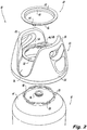
- Fig. 1 a new and unique portable gas cylinder designated generally by reference numeral 10.
- the portable gas cylinder of the subject invention provides a handle assembly 22 for a gas tank 12 with improved ergonomics and portability relative to prior art gas cylinders made from steel, and which are relatively easy and cost effective to manufacture and install.
- the portable gas cylinder 10 includes a gas cylinder or tank 12 for receiving a pressurized gas, such as propane or the like.
- the gas tank 12 includes an upper portion 14 having a valve port 16 and an annular mounting collar 18 surrounding the valve port 16.
- the mounting collar 18 includes a plurality of circumferentially spaced apart radially outwardly extending arcuate flanges 20.
- the portable gas cylinder 10 further includes a handle assembly 22 including a housing 24 having a body portion 26 configured to mate with the upper portion 14 of the gas tank 12.
- the housing 24 includes a pair of diametrically opposed gripping handles 28 and 30 extending upwardly from the body portion 26 and a central aperture 32 providing access to the valve port 16 of the gas tank 12.
- annular retention channel 34 is formed in an undersurface of the housing 24 of handle assembly 22, extending about the periphery of the central aperture 32, for receiving the mounting collar 18 of the gas tank 12.
- a blocking ring 40 is provided for securing the mounting collar 18 of the gas tank 12 within the retention channel 34 of the handle assembly 22.
- the annular retention channel 34 of the handle assembly 22 includes a plurality of circumferentially spaced apart arcuate seating areas 35 and a plurality of circumferentially spaced apart arcuate reception grooves 36 for receiving the plurality of arcuate flanges 20 when the handle assembly 22 is rotated relative to the gas tank 12 upon the mating thereof.
- the seating areas 35 are spaced to readily accommodate the arcuate flanges 20 during the handle assembly process.
- the blocking ring 40 includes an upper horizontal rim portion 52 and lower vertical hub portion 54.
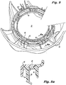
- a pair of diametrically opposed engagement tangs 42 and 44 extend from an outer periphery of the rim portion 52 for engaging a pair of corresponding diametrically opposed engagement ports 46 and 48 formed in the housing 24 of the handle assembly 22 on the periphery of the central aperture 32 (see Fig. 5 ).
- a plurality of circumferentially spaced apart deflectable ramps 56 project radially outwardly from the hub portion 54 of blocking ring 40, as shown in Figs 5 and 5a .
- the ramps 56 are adapted and configured to slide passed the periphery of the central aperture 32 while deflecting radially inwardly and then return to a neutral position mechanically engaged below the undersurface of housing 24, to secure the blocking ring 40 to the housing 24, as best seen in Figs. 5 and 5a .
- an audible indication is produced to enable the assembler to ensure that the blocking ring is firmly secured in place.
- the housing 24 of the handle assembly 22 is mated with the upper portion 14 of the gas tank 12 so that the mounting collar 18 of the gas tank 12 is located within the retention channel 34 of the housing 24, as illustrated in Fig. 3 .
- each arcuate mounting flange 20 of mounting collar 18 is initially accommodated within a corresponding seating area 35 of retention channel 34, as best seen in Fig. 3a .
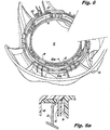
- the handle assembly 22 is rotated through an angle of approximately 30 degrees relative to the upper portion 14 of the gas tank 12. This serves to position the plurality of circumferentially spaced apart arcuate flanges 20 extending radially outwardly from the annular mounting collar 18 within the plurality of circumferentially spaced apart arcuate reception grooves 36 formed within the retention channel 34 of the housing 24, as best seen in Fig. 4a .
- the blocking ring 40 is engaged within the central aperture 32 of the housing 24 to secure the mounting collar 18 of the gas tank 12 within the retention channel 34 of the housing 24, as best seen in Fig 5a .
- the plurality of circumferentially spaced apart deflectable ramps 56 secure the blocking ring 40 to the undersurface of housing 24, as best seen in Fig. 5a .
- the pair of diametrically opposed engagement tangs 42 and 44 are engaged within the corresponding engagement ports 46 and 48 in the housing 24 of handle assembly 22.
Landscapes
- Engineering & Computer Science (AREA)
- Mechanical Engineering (AREA)
- General Engineering & Computer Science (AREA)
- Filling Or Discharging Of Gas Storage Vessels (AREA)
Claims (9)
- Ensemble de poignée (22) pour une bouteille de gaz portable (10) comprenant :a) un logement (24) ayant une partie de corps (26) configurée pour s'accoupler avec une partie supérieure (14) d'une bouteille de gaz (12) et comportant une paire de poignées de préhension diamétralement opposées (28) s'étendant vers le haut à partir de la partie de corps, le logement définissant une ouverture centrale (32) pour accéder à un orifice de soupape (16) de la bouteille, où un canal de retenue annulaire (34) est formé dans une surface inférieure du logement, s'étendant autour de la périphérie de l'ouverture centrale, pour recevoir un collier de montage annulaire (18) de la bouteille de gaz qui entoure l'orifice de soupape ; etb) une bague de blocage (40) pour fixer le collier de montage de la bouteille de gaz dans le canal de retenue de l'ensemble de poignée, caractérisé en ce que le canal de retenue annulaire comporte une pluralité de rainures de réception arquées (36) espacées de manière circonférentielle, adaptées pour recevoir une pluralité de brides arquées (20) espacées de manière circonférentielle s'étendant radialement vers l'extérieur à partir du collier de montage annulaire lorsque l'ensemble de poignée tourne par rapport à la bouteille de gaz lors de son accouplement.
- Ensemble de poignée (22) pour une bouteille de gaz portable (10) selon la revendication 1, dans lequel le canal de retenue annulaire comporte une pluralité de zones de siège arquées espacées de manière circonférentielle (35) adjacentes à la pluralité de rainures de réception arquées espacées de manière circonférentielle, pour recevoir initialement les brides arquées s'étendant radialement vers l'extérieur espacées de manière circonférentielle avant de faire tourner l'ensemble de poignée par rapport à la bouteille de gaz.
- Ensemble de poignée (22) pour une bouteille de gaz portable (10) selon la revendication 1, dans lequel la bague de blocage comporte une partie de rebord horizontal supérieur (52) et une partie de raccord vertical inférieur (54), et où une paire de languettes d'engagement diamétralement opposées s'étendent vers le bas à partir d'une périphérie externe de la partie de rebord pour s'engager avec une paire d'orifices d'engagement diamétralement opposés correspondants formés dans le logement de l'ensemble de poignée sur la périphérie de l'ouverture centrale afin d'empêcher une rotation supplémentaire de l'ensemble de poignée par rapport à la bouteille de gaz en empêchant une bride arquée adjacente du collier de montage de sortir par des rainures de réception arquées.
- Ensemble de poignée (22) pour une bouteille de gaz portable (10) selon la revendication 3, dans lequel la bague de blocage comporte une pluralité de rampes arquées (56) déformables espacées de manière circonférentielle, qui font saillie radialement vers l'extérieur depuis la partie de raccord pour s'engager mécaniquement sous la surface inférieure du logement afin de fixer la bague de blocage au logement.
- Ensemble de poignée (22) pour une bouteille de gaz portable (10) selon la revendication 4, dans lequel les rampes arquées déformables de la bague de blocage sont adaptées et configurées pour produire un son audible lors de l'engagement avec la surface inférieure du logement pour fournir une indication que la bague de blocage est fermement fixée au logement.
- Bouteille à gaz portable (10) comprenant un ensemble de poignée (22) selon les revendications 1 à 5.
- Procédé d'assemblage d'une bouteille de gaz portable (10) comprenant les étapes consistant :a) à prévoir une bouteille de gaz (12) pour recevoir un gaz sous pression, la bouteille comportant une partie supérieure (14) ayant un orifice de soupape (16) et un collier de montage annulaire (18) entourant l'orifice de soupape ;b) à prévoir un ensemble de poignée (22) comportant un logement (24) configuré pour s'accoupler avec la partie supérieure de la bouteille de gaz, le logement ayant une ouverture centrale (32) pour accéder à l'orifice de soupape, et un canal de retenue annulaire (34) formé dans une surface inférieure du logement, s'étendant autour de la périphérie de l'ouverture centrale pour recevoir le collier de montage annulaire de la bouteille de gaz ;c) à accoupler le logement de l'ensemble de poignée avec la partie supérieure de la bouteille de gaz de sorte que le collier de montage de la bouteille de gaz soit situé dans le canal de retenue du logement ; etd) à engager une bague de blocage (40) dans l'ouverture du logement pour fixer le collier de montage de la bouteille de gaz dans le canal de retenue du logement, caractérisé en ce que l'étape consistant à accoupler le logement de l'ensemble de poignée avec la partie supérieure de la bouteille de gaz de sorte que le collier de montage de la bouteille de gaz soit situé dans le canal de retenue du logement comporte le positionnement d'une pluralité de brides arquées espacées de manière circonférentielle (20) s'étendant radialement vers l'extérieur à partir du collier de montage dans une pluralité correspondante de zones de siège arquées espacées de manière circonférentielle formées dans le canal de retenue du logement
- Procédé d'assemblage d'une bouteille de gaz portable (10) selon la revendication 7, comprenant en outre l'étape consistant à faire tourner l'ensemble de poignée par rapport à la bouteille de gaz pour positionner une pluralité de brides arquées espacées de manière circonférentielle s'étendant radialement vers l'extérieur à partir du collier de montage annulaire dans une pluralité de rainures de réception (36) arquées espacées de manière circonférentielle formées dans le canal de réception du logement.
- Procédé d'assemblage d'une bouteille de gaz portable (10) selon la revendication 8, comprenant en outre l'étape consistant à engager une paire de languettes d'engagement diamétralement opposées (42, 44) formées sur la bague de blocage dans une paire d'orifices d'engagement diamétralement opposés correspondants formés dans le logement de l'ensemble de poignée sur la périphérie de l'ouverture centrale pour empêcher une rotation supplémentaire de l'ensemble de poignée par rapport à la bouteille de gaz.
Priority Applications (1)
| Application Number | Priority Date | Filing Date | Title |
|---|---|---|---|
| PL16152362T PL3048358T3 (pl) | 2015-01-23 | 2016-01-22 | Zespół uchwytowy do przenośnej butli na sprężony gaz |
Applications Claiming Priority (1)
| Application Number | Priority Date | Filing Date | Title |
|---|---|---|---|
| US201562107116P | 2015-01-23 | 2015-01-23 |
Publications (2)
| Publication Number | Publication Date |
|---|---|
| EP3048358A1 EP3048358A1 (fr) | 2016-07-27 |
| EP3048358B1 true EP3048358B1 (fr) | 2019-01-16 |
Family
ID=55229573
Family Applications (1)
| Application Number | Title | Priority Date | Filing Date |
|---|---|---|---|
| EP16152362.6A Active EP3048358B1 (fr) | 2015-01-23 | 2016-01-22 | Ensemble poignée pour un cylindre de gaz sous pression portable |
Country Status (6)
| Country | Link |
|---|---|
| US (1) | US9932148B2 (fr) |
| EP (1) | EP3048358B1 (fr) |
| ES (1) | ES2715897T3 (fr) |
| PL (1) | PL3048358T3 (fr) |
| PT (1) | PT3048358T (fr) |
| TR (1) | TR201902115T4 (fr) |
Families Citing this family (22)
| Publication number | Priority date | Publication date | Assignee | Title |
|---|---|---|---|---|
| FR3042585B1 (fr) * | 2015-10-15 | 2018-03-09 | L'air Liquide, Societe Anonyme Pour L'etude Et L'exploitation Des Procedes Georges Claude | Chapeau de protection de robinet de bouteille de fluide sous pression et bouteille comprenant un tel chapeau |
| USD845435S1 (en) * | 2017-08-23 | 2019-04-09 | Amtrol Licensing, Inc. | Gas cylinder |
| US10753541B2 (en) | 2018-05-16 | 2020-08-25 | Amtrol Licensing Inc. | Handle assembly for a portable pressurized gas cylinder |
| USD920468S1 (en) * | 2018-05-16 | 2021-05-25 | Amtrol Licensing Inc. | Handle for a cylinder |
| EP3594555B1 (fr) * | 2018-07-12 | 2022-11-02 | Gasib Sociedad Ibérica De Gas Licuado, S.L.U. | Collier destiné à être monté sur un cylindre d'une bouteille de gaz |
| EP3870889B1 (fr) * | 2018-10-24 | 2024-05-22 | AMTROL Licensing Inc. | Récipient sous pression hybride avec revêtement intérieur en plastique |
| IT201900003865A1 (it) * | 2019-03-18 | 2020-09-18 | Tiziano Briata | Dispositivo di protezione per valvole di bombole di gas compresso o liquefatto, bombola di gas compresso o liquefatto comprendente tale dispositivo e metodo di montaggio. |
| IT201900003869A1 (it) * | 2019-03-18 | 2020-09-18 | Tiziano Briata | Protezione per valvole di bombole di gas compresso o liquefatto, bombola di gas compresso o liquefatto comprendente tale protezione. |
| USD912199S1 (en) * | 2019-04-05 | 2021-03-02 | Amtrol Licensing Inc. | Cylinder |
| ES3008479T3 (en) * | 2019-08-14 | 2025-03-24 | Emanuela Covi | Gripping and closing device for a keg type container |
| USD930783S1 (en) * | 2019-09-03 | 2021-09-14 | Amtrol Licensing, Inc. | Handle |
| US10982814B2 (en) * | 2019-09-03 | 2021-04-20 | Amtrol Licensing Inc. | Handle assembly for a portable pressurized gas cylinder |
| US11584590B2 (en) | 2019-09-09 | 2023-02-21 | Material Handling Innovators Co | Tank sleeve |
| WO2021061075A1 (fr) * | 2019-09-26 | 2021-04-01 | Evas Ev Aletleri̇ Sanayi̇ Anoni̇m Şi̇rketi̇ | Poignée et partie inférieure pour bouteille de gpl |
| USD931979S1 (en) * | 2019-10-23 | 2021-09-28 | Amtrol Licensing, Inc. | Cylinder |
| USD981528S1 (en) * | 2020-04-15 | 2023-03-21 | Worthington Cylinders Corporation | Canister attachment device |
| US11415449B2 (en) * | 2020-04-15 | 2022-08-16 | Worthington Cylinders Corporation | Cylinder attachment |
| US11585491B2 (en) * | 2020-08-06 | 2023-02-21 | Amtrol Licensing Inc. | Handle for a portable cylinder |
| USD930915S1 (en) * | 2020-12-04 | 2021-09-14 | Changli WU | Pet feeder |
| USD1055212S1 (en) * | 2022-07-25 | 2024-12-24 | Amtrol Licensing Inc. | Handle |
| USD1124227S1 (en) | 2023-02-17 | 2026-04-28 | Amtrol Licensing Inc. | Handle |
| US12129970B2 (en) * | 2023-02-17 | 2024-10-29 | Amtrol Licensing Inc. | Handle for a portable cylinder |
Family Cites Families (6)
| Publication number | Priority date | Publication date | Assignee | Title |
|---|---|---|---|---|
| FR2738897B1 (fr) | 1995-09-19 | 1997-12-05 | Butagaz | Ensemble d'un recipient de stockage de gaz liquefie, comprime ou dissous, sous pression, recipient de stockage de gaz sous pression et chapeau de manutention pour un tel recipient |
| FR2791757B1 (fr) * | 1999-04-01 | 2001-06-15 | Air Liquide | Chapeau ouvert composite de grandes bouteilles de gaz industriels et medicaux |
| TR200502730A2 (tr) | 2005-07-13 | 2007-02-21 | Aygaz Anon�M ��Rket� | B |
| JP2007046522A (ja) * | 2005-08-09 | 2007-02-22 | Honda Motor Co Ltd | リッド分離型容器 |
| FR2930317B1 (fr) * | 2008-04-22 | 2010-08-20 | Air Liquide | Ensemble comprenant un robinet et un chapeau de protection, bouteille comprenant un tel ensemble |
| PL2933547T3 (pl) | 2014-04-17 | 2020-01-31 | Schmitt Prof. Möhlmann & Collegen Wirtschaftskanzlei -Insolvenzverwalter Aktiengesellschaft | Kosz ochronny do zaworu dla ochrony zaworów butli gazowych |
-
2016
- 2016-01-19 US US15/000,662 patent/US9932148B2/en active Active
- 2016-01-22 PL PL16152362T patent/PL3048358T3/pl unknown
- 2016-01-22 PT PT16152362T patent/PT3048358T/pt unknown
- 2016-01-22 EP EP16152362.6A patent/EP3048358B1/fr active Active
- 2016-01-22 TR TR2019/02115T patent/TR201902115T4/tr unknown
- 2016-01-22 ES ES16152362T patent/ES2715897T3/es active Active
Non-Patent Citations (1)
| Title |
|---|
| None * |
Also Published As
| Publication number | Publication date |
|---|---|
| EP3048358A1 (fr) | 2016-07-27 |
| PL3048358T3 (pl) | 2019-07-31 |
| PT3048358T (pt) | 2019-02-27 |
| ES2715897T3 (es) | 2019-06-06 |
| US20160215928A1 (en) | 2016-07-28 |
| US9932148B2 (en) | 2018-04-03 |
| TR201902115T4 (tr) | 2019-03-21 |
Similar Documents
| Publication | Publication Date | Title |
|---|---|---|
| US9932148B2 (en) | Handle assembly for a portable pressurized gas cylinder | |
| EP3794271B1 (fr) | Ensemble poignée pour bouteille de gaz comprimé portative | |
| EP3931483B1 (fr) | Pied pour bouteille de gaz comprimé portative | |
| US11097147B2 (en) | Weight plate with lifting flanges | |
| US8875921B2 (en) | Lightweight container having a reinforced base | |
| US10364080B2 (en) | Can carrier | |
| EP3069072B1 (fr) | Poignée pour bouteille à gaz portable ayant un ensemble de verrouillage par encliquetage | |
| US20140158576A1 (en) | Nestable can tray | |
| US20150107695A1 (en) | Protective cap for a pressurised fluid cylinder valve and production method thereof | |
| KR20130109993A (ko) | 용기용 서스펜션 장치 | |
| EP3220040B1 (fr) | Ensemble de carénage pour un cylindre de gaz sous pression portable | |
| CN110072399A (zh) | 带有可移除端盖的装载篮以及使用篮的方法 | |
| US20140119810A1 (en) | Steering wheel shaft retention mechanism assembly and service tool | |
| US20130206777A1 (en) | Cookware | |
| CN110475726A (zh) | 把手和具备把手的容器 | |
| US10343840B2 (en) | Sump pit having disassemblable upper and lower tank portions | |
| US20240172896A1 (en) | Cooking Vessel With Handle Attached By Two Superimposed Rivets | |
| RU2660522C2 (ru) | Шарик для дезодоранта и способ его изготовления | |
| EP3594555B1 (fr) | Collier destiné à être monté sur un cylindre d'une bouteille de gaz | |
| US20240262608A1 (en) | Package for abrasive wheels | |
| EP3312107B1 (fr) | Base de fixation pour récipient d'aérosol | |
| EP3431408B1 (fr) | Bouteille empilable avec deux poignées | |
| JP7267600B2 (ja) | 保護リングおよびそれを含むホイール保護部材セット | |
| KR200455062Y1 (ko) | 조리 용기의 손잡이 | |
| WO2013110977A1 (fr) | Ensemble de couvercles empilables pour batterie de cuisine |
Legal Events
| Date | Code | Title | Description |
|---|---|---|---|
| PUAI | Public reference made under article 153(3) epc to a published international application that has entered the european phase |
Free format text: ORIGINAL CODE: 0009012 |
|
| AK | Designated contracting states |
Kind code of ref document: A1 Designated state(s): AL AT BE BG CH CY CZ DE DK EE ES FI FR GB GR HR HU IE IS IT LI LT LU LV MC MK MT NL NO PL PT RO RS SE SI SK SM TR |
|
| AX | Request for extension of the european patent |
Extension state: BA ME |
|
| STAA | Information on the status of an ep patent application or granted ep patent |
Free format text: STATUS: REQUEST FOR EXAMINATION WAS MADE |
|
| 17P | Request for examination filed |
Effective date: 20170127 |
|
| RBV | Designated contracting states (corrected) |
Designated state(s): AL AT BE BG CH CY CZ DE DK EE ES FI FR GB GR HR HU IE IS IT LI LT LU LV MC MK MT NL NO PL PT RO RS SE SI SK SM TR |
|
| RIC1 | Information provided on ipc code assigned before grant |
Ipc: F17C 1/00 20060101AFI20170922BHEP |
|
| STAA | Information on the status of an ep patent application or granted ep patent |
Free format text: STATUS: EXAMINATION IS IN PROGRESS |
|
| 17Q | First examination report despatched |
Effective date: 20171115 |
|
| GRAP | Despatch of communication of intention to grant a patent |
Free format text: ORIGINAL CODE: EPIDOSNIGR1 |
|
| STAA | Information on the status of an ep patent application or granted ep patent |
Free format text: STATUS: GRANT OF PATENT IS INTENDED |
|
| INTG | Intention to grant announced |
Effective date: 20181023 |
|
| GRAS | Grant fee paid |
Free format text: ORIGINAL CODE: EPIDOSNIGR3 |
|
| GRAA | (expected) grant |
Free format text: ORIGINAL CODE: 0009210 |
|
| STAA | Information on the status of an ep patent application or granted ep patent |
Free format text: STATUS: THE PATENT HAS BEEN GRANTED |
|
| AK | Designated contracting states |
Kind code of ref document: B1 Designated state(s): AL AT BE BG CH CY CZ DE DK EE ES FI FR GB GR HR HU IE IS IT LI LT LU LV MC MK MT NL NO PL PT RO RS SE SI SK SM TR |
|
| REG | Reference to a national code |
Ref country code: GB Ref legal event code: FG4D |
|
| REG | Reference to a national code |
Ref country code: CH Ref legal event code: EP |
|
| REG | Reference to a national code |
Ref country code: IE Ref legal event code: FG4D |
|
| REG | Reference to a national code |
Ref country code: DE Ref legal event code: R096 Ref document number: 602016009304 Country of ref document: DE |
|
| REG | Reference to a national code |
Ref country code: AT Ref legal event code: REF Ref document number: 1089941 Country of ref document: AT Kind code of ref document: T Effective date: 20190215 |
|
| REG | Reference to a national code |
Ref country code: PT Ref legal event code: SC4A Ref document number: 3048358 Country of ref document: PT Date of ref document: 20190227 Kind code of ref document: T Free format text: AVAILABILITY OF NATIONAL TRANSLATION Effective date: 20190220 |
|
| REG | Reference to a national code |
Ref country code: NL Ref legal event code: MP Effective date: 20190116 |
|
| REG | Reference to a national code |
Ref country code: ES Ref legal event code: FG2A Ref document number: 2715897 Country of ref document: ES Kind code of ref document: T3 Effective date: 20190606 |
|
| REG | Reference to a national code |
Ref country code: LT Ref legal event code: MG4D |
|
| PG25 | Lapsed in a contracting state [announced via postgrant information from national office to epo] |
Ref country code: NL Free format text: LAPSE BECAUSE OF FAILURE TO SUBMIT A TRANSLATION OF THE DESCRIPTION OR TO PAY THE FEE WITHIN THE PRESCRIBED TIME-LIMIT Effective date: 20190116 |
|
| REG | Reference to a national code |
Ref country code: AT Ref legal event code: MK05 Ref document number: 1089941 Country of ref document: AT Kind code of ref document: T Effective date: 20190116 |
|
| PG25 | Lapsed in a contracting state [announced via postgrant information from national office to epo] |
Ref country code: LT Free format text: LAPSE BECAUSE OF FAILURE TO SUBMIT A TRANSLATION OF THE DESCRIPTION OR TO PAY THE FEE WITHIN THE PRESCRIBED TIME-LIMIT Effective date: 20190116 Ref country code: NO Free format text: LAPSE BECAUSE OF FAILURE TO SUBMIT A TRANSLATION OF THE DESCRIPTION OR TO PAY THE FEE WITHIN THE PRESCRIBED TIME-LIMIT Effective date: 20190416 Ref country code: FI Free format text: LAPSE BECAUSE OF FAILURE TO SUBMIT A TRANSLATION OF THE DESCRIPTION OR TO PAY THE FEE WITHIN THE PRESCRIBED TIME-LIMIT Effective date: 20190116 Ref country code: SE Free format text: LAPSE BECAUSE OF FAILURE TO SUBMIT A TRANSLATION OF THE DESCRIPTION OR TO PAY THE FEE WITHIN THE PRESCRIBED TIME-LIMIT Effective date: 20190116 |
|
| REG | Reference to a national code |
Ref country code: DE Ref legal event code: R119 Ref document number: 602016009304 Country of ref document: DE |
|
| PG25 | Lapsed in a contracting state [announced via postgrant information from national office to epo] |
Ref country code: RS Free format text: LAPSE BECAUSE OF FAILURE TO SUBMIT A TRANSLATION OF THE DESCRIPTION OR TO PAY THE FEE WITHIN THE PRESCRIBED TIME-LIMIT Effective date: 20190116 Ref country code: GR Free format text: LAPSE BECAUSE OF FAILURE TO SUBMIT A TRANSLATION OF THE DESCRIPTION OR TO PAY THE FEE WITHIN THE PRESCRIBED TIME-LIMIT Effective date: 20190417 Ref country code: HR Free format text: LAPSE BECAUSE OF FAILURE TO SUBMIT A TRANSLATION OF THE DESCRIPTION OR TO PAY THE FEE WITHIN THE PRESCRIBED TIME-LIMIT Effective date: 20190116 Ref country code: BG Free format text: LAPSE BECAUSE OF FAILURE TO SUBMIT A TRANSLATION OF THE DESCRIPTION OR TO PAY THE FEE WITHIN THE PRESCRIBED TIME-LIMIT Effective date: 20190416 Ref country code: LV Free format text: LAPSE BECAUSE OF FAILURE TO SUBMIT A TRANSLATION OF THE DESCRIPTION OR TO PAY THE FEE WITHIN THE PRESCRIBED TIME-LIMIT Effective date: 20190116 Ref country code: IS Free format text: LAPSE BECAUSE OF FAILURE TO SUBMIT A TRANSLATION OF THE DESCRIPTION OR TO PAY THE FEE WITHIN THE PRESCRIBED TIME-LIMIT Effective date: 20190516 |
|
| REG | Reference to a national code |
Ref country code: CH Ref legal event code: PL |
|
| PG25 | Lapsed in a contracting state [announced via postgrant information from national office to epo] |
Ref country code: LU Free format text: LAPSE BECAUSE OF NON-PAYMENT OF DUE FEES Effective date: 20190122 |
|
| REG | Reference to a national code |
Ref country code: BE Ref legal event code: MM Effective date: 20190131 |
|
| REG | Reference to a national code |
Ref country code: IE Ref legal event code: MM4A |
|
| PG25 | Lapsed in a contracting state [announced via postgrant information from national office to epo] |
Ref country code: DE Free format text: LAPSE BECAUSE OF NON-PAYMENT OF DUE FEES Effective date: 20190801 Ref country code: SK Free format text: LAPSE BECAUSE OF FAILURE TO SUBMIT A TRANSLATION OF THE DESCRIPTION OR TO PAY THE FEE WITHIN THE PRESCRIBED TIME-LIMIT Effective date: 20190116 Ref country code: AL Free format text: LAPSE BECAUSE OF FAILURE TO SUBMIT A TRANSLATION OF THE DESCRIPTION OR TO PAY THE FEE WITHIN THE PRESCRIBED TIME-LIMIT Effective date: 20190116 Ref country code: MC Free format text: LAPSE BECAUSE OF FAILURE TO SUBMIT A TRANSLATION OF THE DESCRIPTION OR TO PAY THE FEE WITHIN THE PRESCRIBED TIME-LIMIT Effective date: 20190116 Ref country code: CZ Free format text: LAPSE BECAUSE OF FAILURE TO SUBMIT A TRANSLATION OF THE DESCRIPTION OR TO PAY THE FEE WITHIN THE PRESCRIBED TIME-LIMIT Effective date: 20190116 Ref country code: IT Free format text: LAPSE BECAUSE OF FAILURE TO SUBMIT A TRANSLATION OF THE DESCRIPTION OR TO PAY THE FEE WITHIN THE PRESCRIBED TIME-LIMIT Effective date: 20190116 Ref country code: RO Free format text: LAPSE BECAUSE OF FAILURE TO SUBMIT A TRANSLATION OF THE DESCRIPTION OR TO PAY THE FEE WITHIN THE PRESCRIBED TIME-LIMIT Effective date: 20190116 Ref country code: DK Free format text: LAPSE BECAUSE OF FAILURE TO SUBMIT A TRANSLATION OF THE DESCRIPTION OR TO PAY THE FEE WITHIN THE PRESCRIBED TIME-LIMIT Effective date: 20190116 Ref country code: AT Free format text: LAPSE BECAUSE OF FAILURE TO SUBMIT A TRANSLATION OF THE DESCRIPTION OR TO PAY THE FEE WITHIN THE PRESCRIBED TIME-LIMIT Effective date: 20190116 Ref country code: EE Free format text: LAPSE BECAUSE OF FAILURE TO SUBMIT A TRANSLATION OF THE DESCRIPTION OR TO PAY THE FEE WITHIN THE PRESCRIBED TIME-LIMIT Effective date: 20190116 |
|
| PLBE | No opposition filed within time limit |
Free format text: ORIGINAL CODE: 0009261 |
|
| STAA | Information on the status of an ep patent application or granted ep patent |
Free format text: STATUS: NO OPPOSITION FILED WITHIN TIME LIMIT |
|
| PG25 | Lapsed in a contracting state [announced via postgrant information from national office to epo] |
Ref country code: BE Free format text: LAPSE BECAUSE OF NON-PAYMENT OF DUE FEES Effective date: 20190131 Ref country code: SM Free format text: LAPSE BECAUSE OF FAILURE TO SUBMIT A TRANSLATION OF THE DESCRIPTION OR TO PAY THE FEE WITHIN THE PRESCRIBED TIME-LIMIT Effective date: 20190116 |
|
| 26N | No opposition filed |
Effective date: 20191017 |
|
| PG25 | Lapsed in a contracting state [announced via postgrant information from national office to epo] |
Ref country code: LI Free format text: LAPSE BECAUSE OF NON-PAYMENT OF DUE FEES Effective date: 20190131 Ref country code: CH Free format text: LAPSE BECAUSE OF NON-PAYMENT OF DUE FEES Effective date: 20190131 |
|
| PG25 | Lapsed in a contracting state [announced via postgrant information from national office to epo] |
Ref country code: IE Free format text: LAPSE BECAUSE OF NON-PAYMENT OF DUE FEES Effective date: 20190122 |
|
| PG25 | Lapsed in a contracting state [announced via postgrant information from national office to epo] |
Ref country code: SI Free format text: LAPSE BECAUSE OF FAILURE TO SUBMIT A TRANSLATION OF THE DESCRIPTION OR TO PAY THE FEE WITHIN THE PRESCRIBED TIME-LIMIT Effective date: 20190116 |
|
| PG25 | Lapsed in a contracting state [announced via postgrant information from national office to epo] |
Ref country code: MT Free format text: LAPSE BECAUSE OF NON-PAYMENT OF DUE FEES Effective date: 20190122 |
|
| GBPC | Gb: european patent ceased through non-payment of renewal fee |
Effective date: 20200122 |
|
| PG25 | Lapsed in a contracting state [announced via postgrant information from national office to epo] |
Ref country code: GB Free format text: LAPSE BECAUSE OF NON-PAYMENT OF DUE FEES Effective date: 20200122 |
|
| PG25 | Lapsed in a contracting state [announced via postgrant information from national office to epo] |
Ref country code: CY Free format text: LAPSE BECAUSE OF FAILURE TO SUBMIT A TRANSLATION OF THE DESCRIPTION OR TO PAY THE FEE WITHIN THE PRESCRIBED TIME-LIMIT Effective date: 20190116 |
|
| PG25 | Lapsed in a contracting state [announced via postgrant information from national office to epo] |
Ref country code: HU Free format text: LAPSE BECAUSE OF FAILURE TO SUBMIT A TRANSLATION OF THE DESCRIPTION OR TO PAY THE FEE WITHIN THE PRESCRIBED TIME-LIMIT; INVALID AB INITIO Effective date: 20160122 |
|
| PG25 | Lapsed in a contracting state [announced via postgrant information from national office to epo] |
Ref country code: MK Free format text: LAPSE BECAUSE OF FAILURE TO SUBMIT A TRANSLATION OF THE DESCRIPTION OR TO PAY THE FEE WITHIN THE PRESCRIBED TIME-LIMIT Effective date: 20190116 |
|
| PGFP | Annual fee paid to national office [announced via postgrant information from national office to epo] |
Ref country code: ES Payment date: 20260217 Year of fee payment: 11 |
|
| PGFP | Annual fee paid to national office [announced via postgrant information from national office to epo] |
Ref country code: FR Payment date: 20260121 Year of fee payment: 11 |
|
| PGFP | Annual fee paid to national office [announced via postgrant information from national office to epo] |
Ref country code: TR Payment date: 20260119 Year of fee payment: 11 |
|
| PGFP | Annual fee paid to national office [announced via postgrant information from national office to epo] |
Ref country code: PT Payment date: 20260120 Year of fee payment: 11 |
|
| PGFP | Annual fee paid to national office [announced via postgrant information from national office to epo] |
Ref country code: PL Payment date: 20260109 Year of fee payment: 11 |