EP3048663B1 - Système de stockage d'énergie et procédé de maintien de système de stockage d'énergie - Google Patents
Système de stockage d'énergie et procédé de maintien de système de stockage d'énergie Download PDFInfo
- Publication number
- EP3048663B1 EP3048663B1 EP14846418.3A EP14846418A EP3048663B1 EP 3048663 B1 EP3048663 B1 EP 3048663B1 EP 14846418 A EP14846418 A EP 14846418A EP 3048663 B1 EP3048663 B1 EP 3048663B1
- Authority
- EP
- European Patent Office
- Prior art keywords
- storage battery
- signal
- panel
- maintenance
- state
- Prior art date
- Legal status (The legal status is an assumption and is not a legal conclusion. Google has not performed a legal analysis and makes no representation as to the accuracy of the status listed.)
- Active
Links
Images





Classifications
-
- H—ELECTRICITY
- H01—ELECTRIC ELEMENTS
- H01M—PROCESSES OR MEANS, e.g. BATTERIES, FOR THE DIRECT CONVERSION OF CHEMICAL ENERGY INTO ELECTRICAL ENERGY
- H01M10/00—Secondary cells; Manufacture thereof
- H01M10/42—Methods or arrangements for servicing or maintenance of secondary cells or secondary half-cells
- H01M10/48—Accumulators combined with arrangements for measuring, testing or indicating the condition of cells, e.g. the level or density of the electrolyte
- H01M10/482—Accumulators combined with arrangements for measuring, testing or indicating the condition of cells, e.g. the level or density of the electrolyte for several batteries or cells simultaneously or sequentially
-
- H—ELECTRICITY
- H01—ELECTRIC ELEMENTS
- H01M—PROCESSES OR MEANS, e.g. BATTERIES, FOR THE DIRECT CONVERSION OF CHEMICAL ENERGY INTO ELECTRICAL ENERGY
- H01M10/00—Secondary cells; Manufacture thereof
- H01M10/42—Methods or arrangements for servicing or maintenance of secondary cells or secondary half-cells
- H01M10/4207—Methods or arrangements for servicing or maintenance of secondary cells or secondary half-cells for several batteries or cells simultaneously or sequentially
-
- H—ELECTRICITY
- H01—ELECTRIC ELEMENTS
- H01M—PROCESSES OR MEANS, e.g. BATTERIES, FOR THE DIRECT CONVERSION OF CHEMICAL ENERGY INTO ELECTRICAL ENERGY
- H01M10/00—Secondary cells; Manufacture thereof
- H01M10/42—Methods or arrangements for servicing or maintenance of secondary cells or secondary half-cells
- H01M10/425—Structural combination with electronic components, e.g. electronic circuits integrated to the outside of the casing
-
- H—ELECTRICITY
- H01—ELECTRIC ELEMENTS
- H01M—PROCESSES OR MEANS, e.g. BATTERIES, FOR THE DIRECT CONVERSION OF CHEMICAL ENERGY INTO ELECTRICAL ENERGY
- H01M10/00—Secondary cells; Manufacture thereof
- H01M10/42—Methods or arrangements for servicing or maintenance of secondary cells or secondary half-cells
- H01M10/48—Accumulators combined with arrangements for measuring, testing or indicating the condition of cells, e.g. the level or density of the electrolyte
-
- H—ELECTRICITY
- H02—GENERATION; CONVERSION OR DISTRIBUTION OF ELECTRIC POWER
- H02J—ELECTRIC POWER NETWORKS; CIRCUIT ARRANGEMENTS OR SYSTEMS FOR SUPPLYING OR DISTRIBUTING ELECTRIC POWER; SYSTEMS FOR STORING ELECTRIC ENERGY
- H02J3/00—Circuit arrangements for AC mains or AC distribution networks
- H02J3/28—Arrangements for balancing of the load in networks by storage of energy
- H02J3/32—Arrangements for balancing of the load in networks by storage of energy using batteries or super capacitors with converting means
-
- H—ELECTRICITY
- H02—GENERATION; CONVERSION OR DISTRIBUTION OF ELECTRIC POWER
- H02J—ELECTRIC POWER NETWORKS; CIRCUIT ARRANGEMENTS OR SYSTEMS FOR SUPPLYING OR DISTRIBUTING ELECTRIC POWER; SYSTEMS FOR STORING ELECTRIC ENERGY
- H02J7/00—Circuit arrangements for charging or discharging batteries or for supplying loads from batteries
- H02J7/34—Parallel operation in networks using both storage and other DC sources, e.g. providing buffering
-
- H—ELECTRICITY
- H02—GENERATION; CONVERSION OR DISTRIBUTION OF ELECTRIC POWER
- H02J—ELECTRIC POWER NETWORKS; CIRCUIT ARRANGEMENTS OR SYSTEMS FOR SUPPLYING OR DISTRIBUTING ELECTRIC POWER; SYSTEMS FOR STORING ELECTRIC ENERGY
- H02J7/00—Circuit arrangements for charging or discharging batteries or for supplying loads from batteries
- H02J7/34—Parallel operation in networks using both storage and other DC sources, e.g. providing buffering
- H02J7/35—Parallel operation in networks using both storage and other DC sources, e.g. providing buffering with light sensitive cells
-
- H—ELECTRICITY
- H02—GENERATION; CONVERSION OR DISTRIBUTION OF ELECTRIC POWER
- H02J—ELECTRIC POWER NETWORKS; CIRCUIT ARRANGEMENTS OR SYSTEMS FOR SUPPLYING OR DISTRIBUTING ELECTRIC POWER; SYSTEMS FOR STORING ELECTRIC ENERGY
- H02J7/00—Circuit arrangements for charging or discharging batteries or for supplying loads from batteries
- H02J7/50—Circuit arrangements for charging or discharging batteries or for supplying loads from batteries acting upon multiple batteries simultaneously or sequentially
- H02J7/52—Circuit arrangements for charging or discharging batteries or for supplying loads from batteries acting upon multiple batteries simultaneously or sequentially for charge balancing, e.g. equalisation of charge between batteries
-
- H—ELECTRICITY
- H02—GENERATION; CONVERSION OR DISTRIBUTION OF ELECTRIC POWER
- H02J—ELECTRIC POWER NETWORKS; CIRCUIT ARRANGEMENTS OR SYSTEMS FOR SUPPLYING OR DISTRIBUTING ELECTRIC POWER; SYSTEMS FOR STORING ELECTRIC ENERGY
- H02J7/00—Circuit arrangements for charging or discharging batteries or for supplying loads from batteries
- H02J7/60—Circuit arrangements for charging or discharging batteries or for supplying loads from batteries including safety or protection arrangements
-
- H—ELECTRICITY
- H02—GENERATION; CONVERSION OR DISTRIBUTION OF ELECTRIC POWER
- H02J—ELECTRIC POWER NETWORKS; CIRCUIT ARRANGEMENTS OR SYSTEMS FOR SUPPLYING OR DISTRIBUTING ELECTRIC POWER; SYSTEMS FOR STORING ELECTRIC ENERGY
- H02J7/00—Circuit arrangements for charging or discharging batteries or for supplying loads from batteries
- H02J7/80—Circuit arrangements for charging or discharging batteries or for supplying loads from batteries including monitoring or indicating arrangements
-
- H—ELECTRICITY
- H02—GENERATION; CONVERSION OR DISTRIBUTION OF ELECTRIC POWER
- H02J—ELECTRIC POWER NETWORKS; CIRCUIT ARRANGEMENTS OR SYSTEMS FOR SUPPLYING OR DISTRIBUTING ELECTRIC POWER; SYSTEMS FOR STORING ELECTRIC ENERGY
- H02J9/00—Circuit arrangements for emergency or stand-by power supply, e.g. for emergency lighting
- H02J9/04—Circuit arrangements for emergency or stand-by power supply, e.g. for emergency lighting in which the distribution system is disconnected from the normal source and connected to a standby source
- H02J9/06—Circuit arrangements for emergency or stand-by power supply, e.g. for emergency lighting in which the distribution system is disconnected from the normal source and connected to a standby source with automatic change-over, e.g. UPS systems
- H02J9/061—Circuit arrangements for emergency or stand-by power supply, e.g. for emergency lighting in which the distribution system is disconnected from the normal source and connected to a standby source with automatic change-over, e.g. UPS systems for DC powered loads
-
- H—ELECTRICITY
- H01—ELECTRIC ELEMENTS
- H01M—PROCESSES OR MEANS, e.g. BATTERIES, FOR THE DIRECT CONVERSION OF CHEMICAL ENERGY INTO ELECTRICAL ENERGY
- H01M10/00—Secondary cells; Manufacture thereof
- H01M10/42—Methods or arrangements for servicing or maintenance of secondary cells or secondary half-cells
- H01M10/425—Structural combination with electronic components, e.g. electronic circuits integrated to the outside of the casing
- H01M2010/4271—Battery management systems including electronic circuits, e.g. control of current or voltage to keep battery in healthy state, cell balancing
-
- H—ELECTRICITY
- H01—ELECTRIC ELEMENTS
- H01M—PROCESSES OR MEANS, e.g. BATTERIES, FOR THE DIRECT CONVERSION OF CHEMICAL ENERGY INTO ELECTRICAL ENERGY
- H01M10/00—Secondary cells; Manufacture thereof
- H01M10/42—Methods or arrangements for servicing or maintenance of secondary cells or secondary half-cells
- H01M10/425—Structural combination with electronic components, e.g. electronic circuits integrated to the outside of the casing
- H01M2010/4278—Systems for data transfer from batteries, e.g. transfer of battery parameters to a controller, data transferred between battery controller and main controller
-
- Y—GENERAL TAGGING OF NEW TECHNOLOGICAL DEVELOPMENTS; GENERAL TAGGING OF CROSS-SECTIONAL TECHNOLOGIES SPANNING OVER SEVERAL SECTIONS OF THE IPC; TECHNICAL SUBJECTS COVERED BY FORMER USPC CROSS-REFERENCE ART COLLECTIONS [XRACs] AND DIGESTS
- Y02—TECHNOLOGIES OR APPLICATIONS FOR MITIGATION OR ADAPTATION AGAINST CLIMATE CHANGE
- Y02B—CLIMATE CHANGE MITIGATION TECHNOLOGIES RELATED TO BUILDINGS, e.g. HOUSING, HOUSE APPLIANCES OR RELATED END-USER APPLICATIONS
- Y02B10/00—Integration of renewable energy sources in buildings
- Y02B10/70—Hybrid systems, e.g. uninterruptible or back-up power supplies integrating renewable energies
-
- Y—GENERAL TAGGING OF NEW TECHNOLOGICAL DEVELOPMENTS; GENERAL TAGGING OF CROSS-SECTIONAL TECHNOLOGIES SPANNING OVER SEVERAL SECTIONS OF THE IPC; TECHNICAL SUBJECTS COVERED BY FORMER USPC CROSS-REFERENCE ART COLLECTIONS [XRACs] AND DIGESTS
- Y02—TECHNOLOGIES OR APPLICATIONS FOR MITIGATION OR ADAPTATION AGAINST CLIMATE CHANGE
- Y02E—REDUCTION OF GREENHOUSE GAS [GHG] EMISSIONS, RELATED TO ENERGY GENERATION, TRANSMISSION OR DISTRIBUTION
- Y02E60/00—Enabling technologies; Technologies with a potential or indirect contribution to GHG emissions mitigation
- Y02E60/10—Energy storage using batteries
-
- Y—GENERAL TAGGING OF NEW TECHNOLOGICAL DEVELOPMENTS; GENERAL TAGGING OF CROSS-SECTIONAL TECHNOLOGIES SPANNING OVER SEVERAL SECTIONS OF THE IPC; TECHNICAL SUBJECTS COVERED BY FORMER USPC CROSS-REFERENCE ART COLLECTIONS [XRACs] AND DIGESTS
- Y02—TECHNOLOGIES OR APPLICATIONS FOR MITIGATION OR ADAPTATION AGAINST CLIMATE CHANGE
- Y02P—CLIMATE CHANGE MITIGATION TECHNOLOGIES IN THE PRODUCTION OR PROCESSING OF GOODS
- Y02P90/00—Enabling technologies with a potential contribution to greenhouse gas [GHG] emissions mitigation
- Y02P90/50—Energy storage in industry with an added climate change mitigation effect
Definitions
- the present invention relates to a power storage system using storage batteries and a maintenance technology including preventive maintenance thereof.
- a power storage system charges storage batteries by feeding from a power system, a photovoltaic power generating system, and the like and supplies stable and necessary power to a load in a load facility by discharging from the storage batteries.
- Application examples of a large scale power storage system are to perform peak cut and peak shift of load power consumed in load facilities such as buildings and factories and leveling of natural energy such as sunlight
- lithium-ion storage batteries are used instead of conventional lead-acid storage batteries.
- lithium-ion storage batteries are often more advantageous than lead-acid storage batteries.
- lead-acid storage batteries in case of lithium-ion storage batteries, it is necessary to continuously monitor states of the storage batteries such as voltage in order to ensure soundness. That is, a power storage system is provided with a function of monitoring states of the storage batteries.
- a maintenance person performs maintenance works such as checking malfunctions of the portion including the corresponding storage batteries in accordance with the alarm based on the above signal. The maintenance person then eliminates the malfunction, ensures safety, and resumes operations of this portion.
- Works of the maintenance person include maintenance actions such as periodic maintenance checkups, diagnosis, and examination of storage batteries in the above states such as an abnormal state or a warning state, and replacement of parts.
- Patent Document 1 discloses a configuration of providing terminals for replacing storage batteries in a storage battery system in which a plurality of storage batteries are connected serially and in parallel.
- Patent Document 1 Japanese Patent Application Laid-Open Publication No. 2012-244843
- Representative embodiments of the present invention are a power storage system and a maintenance method, according to product claim1 and method claim 6, including preventive maintenance of the power storage system, and they are characterized in that they include configurations as indicated below.
- a power storage system includes one or more relay panels connected to one or more power control devices; a plurality of storage battery panels connected to the relay panels and equipped with one or more storage batteries; and one or more maintenance devices connected to the relay panels when performing maintenance works including preventive maintenance by a maintenance person, in which the storage battery panel transmits a first signal in which based on monitoring of a state of the storage battery, the state thereof is detected or determined to the superordinate relay panel, the relay panel transmits a second signal based on the first signal to the superordinate power control device, the maintenance device transmits, based on an operation of designating a storage battery panel to be maintained by the maintenance person, a third signal to the superordinate relay panel of the storage battery panel to be maintained, and the relay panel masks and invalidates the first signal from the storage battery panel to be maintained or the second signal based on the first signal in accordance with the third signal.
- a maintenance method of the power storage system is a maintenance method including preventive maintenance of a power storage system which has one or more relay panels connected to one or more power control devices, a plurality of storage battery panels connected to the relay panel and equipped with one or more storage batteries, and one or more maintenance devices connected to the relay panel when performing maintenance works including preventive maintenance by a maintenance person
- the maintenance method of the power storage system including: a first step of transmitting, based on an operation by the maintenance person, a masking start instructing signal from the maintenance device to the superordinate relay panel of a storage battery panel to be maintained and masking and invalidating, in accordance with the masking start instructing signal, a first signal transmitted from the storage battery panel to be maintained to the superordinate relay panel or a second signal transmitted from the relay panel to the superordinate power control device based on the first signal by the relay panel; a second step of performing, based on an operation by the maintenance person, maintenance works for the storage battery panel to be maintained in a state in which the storage battery panel to be maintained is electrically disconnected
- a maintenance method of the power storage system is a maintenance method including preventive maintenance of a power storage system which has one or more relay panels connected to one or more power control devices, a plurality of storage battery panels connected to the relay panel and equipped with one or more storage batteries, and one or more maintenance devices connected to the relay panel when performing maintenance works including preventive maintenance by a maintenance person
- the maintenance method of the power storage system including: a first step of transmitting a first signal in which based on monitoring of a state of the storage battery, the state thereof is detected or determined to the superordinate relay panel by the storage battery panel; a second step of transmitting a second signal based on the first signal to the superordinate power control device by the relay panel; a third step of stopping an operation in units of a subordinate relay panel and the plurality of storage battery panels connected to the relay panel by the power control device based on the second signal; a fourth step of transmitting, based on an operation by the maintenance person, a masking start instructing signal from the maintenance device to the superordinate relay panel of the storage
- maintenance includes preventive maintenance in a broad sense. That is, the maintenance methods according to the embodiments include preventive maintenance methods.
- the stop time in units of storage battery groups becomes long, the user might feel inconvenient For example, when it might take a long time to examine malfunctions of the storage batteries, the stop time becomes long. Moreover, particularly when the power storage system is applied to infrastructure directly linked to individual lives, it is preferable to shorten the stop time as much as possible and to utilize storage batteries in a normal state as much as possible. It is desirable to perform maintenance works in a state in which storage battery groups are operated as much as possible while ensuring safety in performing maintenance works by the maintenance person.
- the storage battery system of Patent Document 1 cannot cope with the problem of stop time when considering an application to a configuration of monitoring storage batteries.
- This system detects states such as an abnormal state or a warning state due to interruption of communication during monitoring of storage batteries when storage batteries using terminals for replacing are replaced. Accordingly, this system will stop operating the portion including the corresponding storage batteries to be replaced. That is, the stop time of the storage battery groups will become long in performing maintenance works.
- the power storage system of the present embodiment shown in FIG 1 and the like enables maintenance works while storage battery groups are in an operating state in performing maintenance works including preventive maintenance of the storage battery facility and it realizes reductions in the stop time of the storage battery groups. Therefore, the power storage system of the present embodiment provides a masking function of masking a signal of monitoring of the storage batteries based on operations in the maintenance device by the maintenance person as shown in FIG 2 and the like.
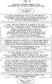
- the maintenance method of the power storage system of the present embodiment includes a step of performing maintenance works based on operations in the maintenance device by the maintenance person by the masking function which regards the storage battery groups of the power storage system as in an operating state, as shown in FIGs. 5 and 6 .
- FIG. 1 shows an overall configuration of the power storage system of the present embodiment.
- the power storage system of the present embodiment includes a plurality of power control devices 1, a plurality of relay panels 2, a plurality of storage battery panels 3 and a maintenance device 5.
- the power storage system of FIG 1 includes PCS1 to PCSN1 which are N1 number ofpower control devices 1, R1 to RN2 which are N2 number of relay panels 2, and L1 to LN3 which are N3 number of storage battery panels 3.
- One power control device 1 connects N4 number of relay panels 2. For example, the case in which N4 is 3 is shown. Further, N2 is N1 ⁇ N4.
- One relay panel 2 connects N5 number of storage battery panels 3.
- N3 is N2 ⁇ N5.
- N5 10 is shown.
- N2 number of relay panels 2 and N3 number of storage battery panels 3 are all defined as objects and ranges to which the masking function in performing maintenance works are applicable.
- Reference numeral 101 denotes a PCS unit in which one power control device 1, a plurality of relay panels 2 and a plurality of storage battery panels 3 connected thereto form a group, wherein there are N1 number thereof ranging from C1 to CN1.
- Reference numeral 102 denotes a relay panel unit in which one relay panel 2 and a plurality of storage battery panels 3 connected thereto form a group, wherein there are N2 number thereof corresponding to R1 to RN2.
- Reference numeral 103 denotes a storage battery panel unit in which a plurality of storage battery packs 4 ( FIG 2 ) constituted by one storage battery panel 3 form a group, wherein there are N3 number thereof corresponding to L1 to LN3.
- the overall power storage system of FIG. 1 is constituted by connecting from C1 which is the first PCS unit 101 connected to PCS1 to CN1 which is the N1th PCS unit 101 connected to PCSN1.
- Reference characters C1 to CN1 which are PCS units 101 are of identical configuration.
- Reference characters PCS1 to PCSN1 are of identical configuration, and it is possible to consider that a single power control device 1 is constituted by connecting or uniting them. Outputs of a single power control device 1 are connected in parallel depending on a necessary amount of power.
- Reference characters PCS 1 to PCSN1 respectively supply power corresponding to a sum of power of each PCS unit 101.
- the power is designed in accordance with power required in a load facility to which they are connected, for example.
- reference characters R1 to R3 which are three relay panels 2 are connected to PCS1.
- reference characters L1 to L10 which are 10 storage battery panels 3 are connected to R1 in parallel.
- a single storage battery panel 3 is equipped with a plurality of storage battery packs 4 ( FIGs. 2 and 3 ).
- reference characters b1 to bN6 which are N6 numbers of storage battery packs 4 ( FIG 3 ) are serially connected to L1.
- the power control device 1 is a PCS (power conditioning system) and performs control of the power storage system and has a function of controlling charge/discharge of the storage battery groups connected thereto through the relay panels 2.
- the PCS is connected to a power system, a load facility, a photovoltaic power generating system, and the like.
- the PCS charges the storage batteries with power from the power system, the photovoltaic power generating system, or the like and supplies power obtained by discharging from the storage batteries to the load of the load facility.
- states of the storage batteries such as an abnormal state or a warning state are detected by a signal from a subordinate relay panel 2
- the power control device 1 When states of the storage batteries such as an abnormal state or a warning state are detected by a signal from a subordinate relay panel 2, the power control device 1 generates an alarm and stops operating the PCS unit 101 which is the subordinate system portion.
- the PCS includes a DC/DC converter, a DC/AC inverter, and the like as a function of converting direct current (DC) or alternating current (AC) power for stably adjusting and utilizing power of the storage batteries or photovoltaic generation.
- DC direct current
- AC alternating current
- the power control devices 1 do not need to be equipped with specific functions, and it is also possible to use hardware and software of conventional PCS. Stopping operations of storage batteries and the like in the present embodiment means stopping charging/discharging functions, and in the stopped state, charge of the storage batteries and discharge from the storage batteries do not work
- the maintenance device 5 is connected to the relay panels 2 by the maintenance person U when maintenance works are required.
- the maintenance device 5 is constituted in the form of a personal computer and the like.
- the maintenance device 5 may also be constituted by an exclusive device or circuit.
- Reference numeral 113 denotes L2 which is an example of a storage battery panel 3 to be maintained.
- Reference numeral 112 denotes R1 which is an example of a relay panel 2 to be connected as a superordinate of the storage battery panel 3 to be maintained.
- the maintenance device 5 is connected to R1 in performing maintenance works of, for example, L2, as an object to be maintained.
- the connection of the maintenance device 5 and the relay panel 2 (R1) of FIG 1 is one example, and it is possible to connect any one of the relay panels 2. Also, by providing a plurality of maintenance devices 5, different maintenance devices 5 may be connected to some of the relay panels 2, respectively. Moreover, a single maintenance device 5 may be connected to some of the relay panels 2. Further, a plurality of maintenance persons may use the respective maintenance devices 5.
- connections between the components may be direct connections or indirect connections in which other elements are interposed therebetween.
- the connection between the maintenance device 5 and the relay panel 2 may be an indirect connection in which a communication network, a communication device, or the like are interposed therebetween, so that remote operations, that is, remote maintenance works can be performed.
- elements such as the power control device 1 and the relay panel 2 are provided in plural number; however, the present invention is not limited to this, and a configuration employing a single number of each device is also possible.
- it might be a system using a single relay panel 2.
- the storage battery panel 3 is equipped with a single storage battery.
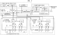
- FIG. 2 shows connection of the devices of the respective components of the power storage system of FIG. 1 and a configuration of functional blocks.
- the power control device 1 includes a control unit 11, a communication unit 12, and a power connecting unit 13.
- the control unit 11 includes a CPU, a memory, and the like and performs control processes of the power control device 1.
- the communication unit 12 performs communication processes with a communication unit of a supervising BCU 21 of the relay panel 2.
- the power connecting unit 13 is a portion connecting a plurality of terminals of a parallel connecting unit 22 of the relay panel 2 in a group and including terminals for inputting/outputting storage battery voltages.
- the relay panel 2 includes the supervising BCU 21, the parallel connecting unit 22, and a connecting unit 23.
- the supervising BCU 21 includes a CPU, a memory, and the like and is a component of a storage battery control unit in a broad sense to be described later.
- the supervising BCU 21 is communicated and connected to the control unit 11 of the superordinate power control device 1 and BCUs 31 of the respective subordinate storage battery panels 3.
- the parallel connecting unit 22 is an interface unit for connecting a plurality of storage battery panels 3 (for example, L1 to L10) in parallel to the relay panel 2.
- the parallel connecting unit 22 includes terminals for connecting main circuit wires of the respective storage battery panels 3.
- the connecting unit 23 is an interface unit for connecting the maintenance device 5 to the relay panel 2 and includes a terminal for connecting, for example, a cable.
- the relay panel 2 is provided with functions of connecting, monitoring, calculating SOCs, and the like of the plurality of storage battery panels 3.
- the storage battery panel 3 is equipped with a plurality of BCUs 31, a plurality of storage battery monitoring units 32 and a storage battery block 40.
- the BCU 31 includes a CPU, a memory, and the like and is a component of the storage battery control unit in a broad sense to be described later.
- the storage battery block 40 includes a plurality of serially connected storage battery packs 4, disconnecting switches 41 on both ends, and a fuse 42 on one end.
- the storage battery panel 3 is provided with functions of connecting, monitoring, calculating SOCs, and the like of the storage battery packs 4.
- the BCUs 31 each are of identical configuration, and representative one of the BCUs 31 is connected to the supervising BCU 21 of the superordinate relay panel 2, for example.
- the plurality of storage battery monitoring units 32 are connected to the BCU 31.
- the plurality of storage battery monitoring units 32 function as monitoring units of the storage battery block 40.
- One storage battery monitoring unit 32 monitors and detects states such as voltage, current, and temperature of one or more storage batteries pack 4 in the storage battery block 40.
- the storage battery monitoring units 32 each are of identical configuration. Note that it is also possible to employ a form in which the storage battery monitoring units 32 are integrated into the BCU 31.
- the BCU 31 uses the plurality of storage battery monitoring units 32 to continuously monitor states of equipment and circuits such as the plurality of storage battery packs 4 in the storage battery block 40 in the storage battery panel 3 or the peripheral power sources thereof.
- the maintenance device 5 includes a control unit 51, a communication unit 52, a connecting unit 53, and a screen unit 54.
- the control unit 51 performs control processes of the maintenance device 5.
- the communication unit 52 performs communicating processes with the relay panel 2 and the power control device 1 connected through the connecting unit 53.
- the connecting unit 53 is an interlace unit for connection in the case in which the maintenance device 5 is connected to the relay panel 2 and the like.
- the connecting unit 23 of the relay panel 2 and the connecting unit 53 of the maintenance device 5 are connected via a cable for performing communication.
- the screen unit 54 configures and provides a screen serving as a user interface when the maintenance person U performs maintenance works based on the control processes of the control unit 51.
- the maintenance device 5 performs processes corresponding to support functions including the masking function in performing maintenance works and provides a screen corresponding to these functions and shown in FIG 7 to be described later by the screen unit 54.
- the maintenance person can input instructions of starting or cancelling masking using the screen. Accordingly, a masking signal M is transmitted from the maintenance device 5 to the relay panel 2.
- Reference character F1 denotes a flag signal which is transmitted from, for example, L1 or L2 which are storage battery panels 3 to, for example, reference character R1 which is a superordinate relay panel 2 based on monitoring.
- Reference character F2 denotes a flag signal which is transmitted from R1 which is the relay panel 2 to, for example, reference character PCS 1 which is a superordinate power control device 1.
- the relay panel 2 performs a process of masking the corresponding flag signal to exclude a storage battery panel 3 to be maintained and designated by the mask signal M from an object to be monitored.
- R1 which is a relay panel 2 transmits a flag signal F2 to the PCS1 which is a superordinate power control device 1 in a state in which it has been determined that the flag signal F1 from storage battery panel as an object to be masked is invalid. Accordingly, the superordinate power control device 1 is set to be a state in which operation of the PCS unit 101 including the object storage battery panel 3 is allowed to be resumed from a state in which operation thereof is not allowed to be stopped or is allowed to be stopped once.
- FIG 3 shows a configuration of connecting a plurality of storage battery panels 3 and main circuit wires in a relay panel unit 102.
- a plurality of storage battery panels 3 are connected in parallel to, for example, R1, which is a relay panel 2, through switches, main circuit wires 301 of positive electrode and main circuit wires 302 of negative electrode.
- R1 which is a relay panel 2
- FIG 4 Within a single storage battery block 40, there are serially connected a plurality of storage battery cells ( FIG 4 ) of N6 number of storage battery packs 4 indicated as b1 to bN6.
- One storage battery pack 4 includes one or more storage battery cells 7. All of the storage battery cells 7 are lithium-ion storage batteries in the present embodiment Note that, in FIG. 3 , the configuration within the storage battery panel 3 is simplified with only the storage battery block 40 illustrated.
- Disconnecting switches 41 are provided on both ends of the storage battery blocks 40.
- One disconnecting switch 41 on one end of the storage battery blocks 40 is provided with the fuse 42.
- ON/OFF states of the disconnecting switches 41 are switched in accordance with functions of charge/discharge and storage battery protection.
- the disconnecting switches 41 are switched ON/OFF based on control of the BCU 31 in attaching and detaching the storage battery blocks 40.
- the fuse 42 is a protection circuit and is automatically cut off when the voltage difference between the plurality of storage battery packs 4 is large and there is an overload state, for example. Note that it is possible to omit the fuse 42 in some cases and the disconnecting switch 41 may have a function corresponding to that of the fuse 42.
- values of the voltage and SOC (state of charge: referred to as charged state or charging rate) of the storage battery packs 4 connected in parallel to the relay panel 2 and in the plurality of storage battery blocks 40 are uniform at predetermined values. That is, it is necessary that differences in potential and SOC fall within predetermined ranges. When they are not uniform, currents exceeding prescribed values might flow in replacing storage battery blocks 40 and the like, thereby not being safe.
- FIG 1 and the like examples in which malfunctions such as a failure of storage battery facilities and abnormal and warning states corresponding thereto occur according to the related-art power storage system are as follows. Note that it is assumed that the related-art power storage system includes storage battery facilities similar to those of FIG 1 . Further, it is assumed that in the example in which a failure occurs, one storage battery pack 4, for example, 310 in FIG 3 , of L2 which is, for example, a storage battery panel 3 in FIG 1 fails. It is assumed that it is necessary to maintain one storage battery block 40 including the storage battery pack 4 of 310 in L2.
- a flag signal F1 indicating an abnormal state or the like due to the above failure is transmitted from the L2 which is the storage battery panel 3 to R1 which is a superordinate relay panel 2 by the function of monitoring the storage batteries, and a similar flag signal F2 is transmitted from R1 to PCS1 which is a superordinate power control device 1.
- the PCS1 Based on this flag signal F2, the PCS1 outputs an alarm and further stops operation in units of the PCS 101 of C1 including R1 which includes L2.
- all of the 30 storage battery panels 3, L1 to L30 become a state in which charge/discharge functions are prohibited.
- the stopped state of the PCS unit 101 of C1 continues.
- the power control device can control operation and stop in units of PCSs but it cannot control charge/discharge in units of individual relay panels or in units of individual storage battery panels of storage battery groups in units of PCSs since they are connected in parallel. Supposing that in a storage battery group of a PCS unit, one storage battery panel is in a state in which charge/discharge is stopped while another storage battery panel is in a state in which charge/discharge is in operation, a difference in SOC occurs in the storage battery group due to the differences in charge/discharge. Accordingly, overcharge, overdischarge, or the like may occur, so that it is impossible to ensure soundness.
- the related-art power storage system controls operation and stop in units of PCSs for ensuring soundness.
- the related-art power storage system stops operation in units of relay panels including these storage battery panels and in units of PCSs including these relay panels, even in a case in which a single storage battery panel fails.
- the power storage system of the present embodiment utilizes the masking function based on an operation from the maintenance device by a maintenance person in order to enable maintenance works in a state in which PCS units 101 of the storage battery pack 4 groups are operating. Accordingly, it is possible to instruct masking to temporally exclude a storage battery panel 3 to be maintained from an object to be monitored in the storage battery packs 4. In other words, it is possible to temporally mask and invalidate signals indicating states such as an abnormal state, a warning state, or the like which are transmitted from the storage battery panels 3 to the power control device 1 via the relay panels 2 by monitoring the storage battery packs 4.
- the superordinate power control device 1 Since the superordinate power control device 1 does not receive flag signals F2 indicating states such as an abnormal state, a warning state, or the like by executing the masking, storage battery pack 4 groups of PCS units 101 including storage battery panels 3 to be maintained will be in states in which they are not stopped, that is, in which they are operating. Masking allows the power control device 1 to see the subordinate relay panels 2 and the like being in a normal state. It is possible to perform maintenance works such as replacement of the storage battery blocks 40 by the maintenance person in a condition in which PCS units 101 are operating. When signals indicating states such as a warning state are being issued, it is possible to arbitrarily execute masking in accordance with judgments and confirmations of the states by the maintenance person.
- FIG 4 shows a configuration of the supervising BCU 21 of the relay panels 2, the BCU 31 and the storage battery monitoring unit 32 of the storage battery panel 3 and a configuration example of flag signals and masking signals.
- the BCU 31 includes a control unit 311, a calculating unit 312, and a communication unit 313.
- the control unit 311 makes determinations related to the states of the storage battery cells 7 using the detection signals 401 from the storage battery monitoring unit 32 and transmits flag signals F1 indicating states such as a normal state, an abnormal state, a warning state obtained through the determination to the supervising BCU 21 of the superordinate relay panel 2 via the communication unit 313.
- the calculating unit 312 calculates SOC values and the like of the storage battery blocks 40 using the measured values transmitted from the storage battery monitoring unit 32.
- the communication unit 313 performs communication processes with the supervising BCU 21 and the storage battery monitoring unit 32.
- States of the flag signals F1 and F2 are three types such as a normal state, a warning state, or an abnormal state in the present embodiment Note that it is possible to use detailed code signals to be described later as the flag signals.
- the supervising BCU 21 of the relay panel 2 receives a flag signal F1 from the subordinate storage battery panel 3.
- the control unit 211 determines the state of the subordinate storage battery panel 3 using the flag signal F1 and transmits a flag signal F2 based on the determination to the superordinate power control device 1 via the communication unit 213.
- the calculating unit 212 calculates SOC values and the like in units of storage battery pack 4 groups of the plurality of storage battery panels 3 using information from the storage battery panel 3 and the flag signal F1. Note that the supervising BCU 21 may also transmit the flag signal F1 as it is from the subordinate storage battery panel 3 to the superordinate power control device 1 as the flag signal F2.
- a masking signal M is transmitted from the maintenance device 5 to the supervising BCU 21 of the superordinate relay panel 2 to which the storage battery panel 3 to be maintained is connected.
- the supervising BCU 21 of the relay panel 2 receives the masking signal M from the maintenance device 5.
- the masking start instructing signal M1 is an instructing signal for starting masking and the masking cancel instructing signal M2 is an instructing signal for canceling masking.
- the supervising BCU 21 When the masking start instructing signal M1 is received, the supervising BCU 21 starts invalidation by the masking of the flag signal F2 based on the flag signal F1 so as to exclude the storage battery panel 3 to be designated by the signal M1 from an object to be monitored.
- the masking cancel instructing signal M2 When the masking cancel instructing signal M2 is received, the supervising BCU 21 cancels the masking state of the flag signal F2 and validates the flag signal.
- invalidation by the masking is assumed that the flag signal F2 itself is not transmitted to the power control device 1 in a case in which the content of the original flag signal F2 indicates the state such as an abnormal state or a warning state.
- invalidation by the masking may be assumed that the state such as an abnormal state or a warning state which is the content of the flag signal F2 is changed to a normal state to be transmitted to the power control device 1.
- invalidation by the masking may be assumed that the state such as an abnormal state or a warning state, which is the content of the flag signal F2, is changed to a state indicating that specific masking is being performed to be transmitted to the power control device 1. Note that, in such a case, the power control device 1 needs to be implemented with a different function than usual, so that it can recognize states of masking indicated by the flag signals F2.
- the control unit 11 of the power control device 1 Upon reception of the flag signal F2 from the supervising BCU 21 of the subordinate relay panel 2, the control unit 11 of the power control device 1 stops operations of charge/discharge functions of the PCS unit 101 including the subordinate relay panel 2 when the state indicated by the flag signal F2 is an abnormal state or a warning state.
- the control unit 11 of the power control device 1 operates charge/discharge functions in the PCS unit 101 including the subordinate relay panel 2.
- FIG 5 shows a process flow when maintenance checkup of a storage battery panel unit 103 is performed as an example of maintenance works including preventive maintenance by a maintenance person, as a first process flow in performing maintenance works using the power storage system and the maintenance method of the first embodiment.
- Reference character S1 and the like indicate steps of processes and works.
- Preventive maintenance as used herein indicates maintenance checkup when stopping of the system and the like has been planned in advance.
- maintenance works for peripheral equipment and circuits such as the power source other than the storage battery packs 4 provided in the storage battery panels 3 as objects to be maintained can be similarly performed.
- detection and determination is performed as the "abnormal" state due to a failure
- the masking function is similarly applicable also to cases of other states. For example, when detecting and determining interruption of communication through monitoring of the storage battery packs 4 as a "warning" state, it is possible to perform masking of the flag signal F2 indicating warning thereby.
- top priority is given to ensuring safety when utilizing the masking function in performing maintenance works, and masking is executed upon confirmation and judgment of states by the maintenance person. For example, when it has been confirmed that effects of a storage battery panel 3 in an "abnormal" state are limited to be within the storage battery panel 3, the maintenance person can perform masking of this storage battery panel 3 to be maintained.
- FIG 7 shows a screen example of a masking function in performing maintenance works in the maintenance device 5.
- the maintenance device 5 provides an interface for supporting maintenance works including the masking function.
- the maintenance person can easily utilize the masking function while confirming states of the power storage system on the screen of the maintenance device 5.
- the maintenance person sets an instruction of masking a storage battery panel 3 to be maintained on the screen for the masking function.
- the table 700 includes items of relay panel 701, storage battery panel 702, state 703 and masking 704.
- the relay panel 701 displays a piece of identification information of the relay panels 2.
- the storage battery panel 702 displays pieces of identification information of the storage battery panels 3.
- the state 703 displays states of the storage battery panels 3 based on the above-described flag signals.
- the states include a normal state, a warning state, an abnormal state, and the like. It is also possible to use code information which is described later and is more detailed than the flag signals in the states 703.
- the masking 704 displays check buttons for designating presence/absence of masking for each of the storage battery panels 3.
- the maintenance person can confirm states of the plurality of storage battery panels 3 for each of the relay panels 2, and by turning on the check buttons on the item of the masking 704, it is possible to designate masking of storage battery panels 3 to be maintained.
- the maintenance person can instruct start of masking corresponding to the state of the masking 704 in the table 700 by pressing a masking start button indicated by 711.
- the above-described masking start instructing signal M1 is transmitted.
- the masking cancel button indicated by 712 it is possible to instruct cancel of masking corresponding to the state of the masking in the table 700.
- the above-described masking start instructing signal M2 is transmitted.
- the screen of the masking function is not limited to the style of the table shown in FIG. 7 , and it is also possible to employ a style in which a connection configuration as that of FIG 1 is shown graphically wherein the maintenance person can designate an object storage battery panel therefrom.
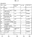
- FIG 8 shows examples of code signals which is a configuration example related to signals issued based on monitoring of the storage batteries.
- a related-art power storage system issues code signals illustrated in FIG 8 as signals by monitoring. Also in the power storage system of the present embodiment, not only the above-described flag signals, but also such code signals can be used.
- code "00” indicates a normal state, and no flags such as abnormal or warning are generated.
- Code "01” indicates “operational upper limit voltage” which is output when the voltage of storage batteries becomes 500 V or more, and the type is “warning.”
- Code “02” indicates “overcharge” which is output when the total voltage of a relay panel becomes 520 V or more, and the type is “abnormal.”
- Code “03” indicates “operational lower limit voltage” which is output when the voltage of storage batteries becomes 360 V or less, and the type is “warning.”
- Code “04” indicates “overdischarge” which is output when the total voltage of a relay panel becomes 300 V or less, and the type is “abnormal.”
- Code “05” indicates “overcurrent” which is output when the voltage of storage batteries becomes 180 A or more, and the type is “warning.”
- Code “08” indicates “abnormal storage battery temperature” which is output when the temperature of a storage battery pack 4 becomes 60 degrees Celsius or more, and the type is “abnormal.”
- Code “09” indicates “communication interruption” which is output when communication between a BCU 31 and a supervising BCU 21 has been interrupted for two minutes or more, and the type is “abnormal.”
- Code “10” indicates “BCU failure” which is output when a BCU 31 fails, and the type is “abnormal.”
- the present embodiments make it possible to perform maintenance works in a state in which storage battery groups other than storage batteries to be maintained are in operation by utilizing the masking function with respect to the time of stopping storage battery groups based on monitoring of the storage batteries. Specifically, it is possible to perform maintenance works in a state in which storage battery groups are in operation, in a large-sized power storage system which includes a large number of lithium ion rechargeable storage batteries and the function of monitoring thereof and is assumed to be used regularly.
- a maintenance person can utilize the masking function in accordance with a judgment of the state and degree of the malfunction. The maintenance person can easily utilize the masking function while confirming the state on a screen of the maintenance device.
- the present invention is applicable to a power storage system and preventive maintenance and a maintenance work thereof.
Landscapes
- Engineering & Computer Science (AREA)
- Power Engineering (AREA)
- Manufacturing & Machinery (AREA)
- Chemical & Material Sciences (AREA)
- Chemical Kinetics & Catalysis (AREA)
- Electrochemistry (AREA)
- General Chemical & Material Sciences (AREA)
- Microelectronics & Electronic Packaging (AREA)
- Business, Economics & Management (AREA)
- Emergency Management (AREA)
- Charge And Discharge Circuits For Batteries Or The Like (AREA)
- Secondary Cells (AREA)
Claims (9)
- Système de stockage d'énergie comprenant :une pluralité de panneaux de batteries d'accumulateurs (3) dans lesquels chaque panneau de batteries d'accumulateurs est équipé d'une ou plusieurs batteries d'accumulateurs ;un ou plusieurs panneaux de relais (2) connectés électriquement, et connectés en communication à la pluralité de panneaux de batteries d'accumulateurs ;un ou plusieurs dispositifs de commande de puissance (1) connectés électriquement audit un ou auxdits plusieurs panneaux de relais et connectés en communication audit un ou auxdits plusieurs panneaux de relais, et commandant la charge/décharge de la pluralité de panneaux de batteries d'accumulateurs ; etun dispositif de maintenance (5) destiné à prendre en charge des travaux de maintenance de la pluralité de panneaux de batteries d'accumulateurs, réalisés par un technicien de maintenance ;caractérisé en ce que le panneau de batteries d'accumulateurs inclut :une unité de surveillance (32) apte à surveiller un état incluant une tension, un courant et une température de ladite une ou desdites plusieurs batteries d'accumulateurs ; etune unité de commande de batteries d'accumulateurs (BCU31) apte à transmettre, au panneau de relais, sur la base de la surveillance de l'état, un premier signal (F1) en vue de transmettre l'état au panneau de relais ; etle panneau de relais inclut :une unité de connexion en parallèle (22) à laquelle ladite une ou lesdites plusieurs batteries d'accumulateurs de la pluralité de panneaux de batteries d'accumulateurs sont connectées en parallèle ;une unité de connexion (23) à laquelle le dispositif de maintenance est connecté en communication ; etune unité de commande de batteries d'accumulateurs de supervision (unité BCU21 de supervision) apte à recevoir le premier signal et apte à transmettre un deuxième signal (F2) visant à transmettre l'état indiqué par le premier signal au dispositif de commande de puissance ;le dispositif de commande de puissance est apte à recevoir le deuxième signal, et lorsque l'état indiqué par le deuxième signal correspond à un état spécifique, il est apte à mettre en œuvre une commande de sorte que la pluralité de panneaux de batteries d'accumulateurs n'opère pas dans des unités de la pluralité de panneaux de batteries d'accumulateurs incluant le panneau de batteries d'accumulateurs qui est connecté au panneau de relais et à partir duquel le premier signal a été transmis ;le dispositif de maintenance inclut :une unité de connexion (53) destinée à être connectée en communication au panneau de relais, l'unité de connexion qui est connectée en communication au panneau de relais étant connectée au panneau de batteries d'accumulateurs devant faire l'objet d'une opération de maintenance, parmi la pluralité de panneaux de relais, par le technicien de maintenance, avant que le technicien de maintenance ne commence les travaux de maintenance sur un panneau de batteries d'accumulateurs devant faire l'objet d'une opération de maintenance, parmi la pluralité de panneaux de batteries d'accumulateurs, et l'unité de connexion étant déconnectée en communication du panneau de relais par le technicien de maintenance lorsque les travaux de maintenance sont achevés ;une unité d'écran (54) apte à recevoir une opération d'entrée saisie par le technicien de maintenance, et apte à afficher un écran, pour prendre en charge les travaux de maintenance, au technicien de maintenance ; etune unité de commande (51) apte à transmettre un troisième signal (M), destiné à invalider temporairement le premier signal ou le deuxième signal, à l'unité de commande de batteries d'accumulateurs de supervision du panneau de relais connecté au panneau de batteries d'accumulateurs devant faire l'objet d'une opération de maintenance, lorsqu'une opération désignant le panneau de batteries d'accumulateurs devant faire l'objet d'une opération de maintenance par le technicien de maintenance est reçue par l'intermédiaire de l'unité d'écran ; etdans lequel l'unité de commande de batteries d'accumulateurs de supervision du panneau de relais, lors de la réception du troisième signal, est apte à invalider temporairement le premier signal ou le deuxième signal.
- Système de stockage d'énergie selon la revendication 1,
dans lequel l'unité de commande du dispositif de maintenance est apte à transmettre, lors de la réception, par l'intermédiaire de l'unité d'écran, de l'opération d'instruction de début d'invalidation, pour le panneau de batteries d'accumulateurs devant faire l'objet d'une opération de maintenance par le technicien de maintenance, un signal de début d'invalidation, sous la forme du troisième signal, et, apte à transmettre, lors de la réception d'une opération d'instruction de fin d'invalidation, un signal de fin d'invalidation, sous la forme du troisième signal ; et
dans lequel l'unité de commande de batteries d'accumulateurs de supervision du panneau de relais est apte à démarrer, lorsque le signal de début d'invalidation est reçu, l'invalidation du premier signal ou du deuxième signal, et est apte à mettre fin, lorsque le signal de fin d'invalidation est reçu, à l'invalidation du premier signal ou du deuxième signal. - Système de stockage d'énergie selon la revendication 1,
dans lequel l'unité d'écran du dispositif de maintenance est apte à afficher, sur l'écran, un élément d'affichage d'un élément d'informations d'identification et l'état de chaque panneau de la pluralité de panneaux de batteries d'accumulateurs, un élément de sélection et de désignation d'un panneau de batteries d'accumulateurs correspondant à un objet de l'invalidation correspondant au panneau de batteries d'accumulateurs devant faire l'objet d'une opération de maintenance parmi la pluralité de panneaux de batteries d'accumulateurs, et un élément de saisie d'une instruction sur le troisième signal pour l'invalidation. - Système de stockage d'énergie selon la revendication 1,
dans lequel le premier signal ou le deuxième signal inclut un état normal, un état anormal ou un état d'avertissement, en tant que l'état ; et
lorsque l'état est un état anormal ou un état d'avertissement, l'invalidation est applicable. - Système de stockage d'énergie selon la revendication 1,
dans lequel le premier signal ou le deuxième signal inclut un signal de code indiquant au moins un état de surtension, de surintensité, de surcharge, de décharge excessive, de température excessive, ou d'interruption de communication ; et
dans lequel, lorsque l'état correspond à un signal de code spécifique indiquant un état spécifique, l'invalidation est applicable. - Procédé de maintenance mis en œuvre dans un système de stockage d'énergie incluant :une pluralité de panneaux de batteries d'accumulateurs dans lesquels chaque panneau de batteries d'accumulateurs est équipé d'une ou plusieurs batteries d'accumulateurs ;un ou plusieurs panneaux de relais connectés électriquement, et connectés en communication à la pluralité de panneaux de batteries d'accumulateurs ;un ou plusieurs dispositifs de commande de puissance connectés électriquement audit un ou auxdits plusieurs panneaux de relais et connectés en communication audit un ou auxdits plusieurs panneaux de relais, et commandant la charge/décharge de la pluralité de panneaux de batteries d'accumulateurs ; etun dispositif de maintenance destiné à prendre en charge des travaux de maintenance de la pluralité de panneaux de batteries d'accumulateurs, réalisés par un technicien de maintenance ;dans lequel le procédé de maintenance comprend les étapes ci-dessous dans lesquelles :le panneau de batteries d'accumulateurs transmet, au panneau de relais, sur la base de la surveillance d'un état incluant une tension, un courant et une température d'une ou plusieurs batteries d'accumulateurs, un premier signal pour transmettre l'état au panneau de relais ;le panneau de relais reçoit le premier signal et transmet, au dispositif de commande de puissance, un deuxième signal pour transmettre l'état indiqué par le premier signal au dispositif de commande de puissance ;le dispositif de commande de puissance reçoit le deuxième signal, et lorsque l'état indiqué par le deuxième signal correspond à un état spécifique, met en œuvre une commande de sorte que la pluralité de panneaux de batteries d'accumulateurs n'opère pas dans des unités de la pluralité de panneaux de batteries d'accumulateurs incluant le panneau de batteries d'accumulateurs qui est connecté au panneau de relais et à partir duquel le premier signal a été transmis ;avant que le technicien de maintenance ne commence les travaux de maintenance sur un panneau de batteries d'accumulateurs devant faire l'objet d'une opération de maintenance, parmi la pluralité de panneaux de batteries d'accumulateurs, le technicien de maintenance connecte le dispositif de maintenance en communication avec le panneau de relais connecté au panneau de batteries d'accumulateurs devant faire l'objet d'une opération de maintenance, parmi la pluralité de panneaux de relais ;le dispositif de maintenance reçoit l'opération d'entrée saisie par le technicien de maintenance, et affiche un écran, pour prendre en charge les travaux de maintenance, au technicien de maintenance, et lors de la réception, par l'intermédiaire de l'écran, d'une opération désignant le panneau de batteries d'accumulateurs devant faire l'objet d'une opération de maintenance par le technicien de maintenance, il transmet un troisième signal pour invalider temporairement le premier signal ou le deuxième signal, au panneau de relais connecté au panneau de batteries d'accumulateurs devant faire l'objet d'une opération de maintenance ;le panneau de relais, lors de la réception du troisième signal, invalide temporairement le premier signal ou le deuxième signal ;les travaux de maintenance du panneau de batteries d'accumulateurs devant faire l'objet d'une opération de maintenance par le technicien de maintenance sont mis en œuvre dans un état où l'invalidation est mise en œuvre et où les panneaux de batteries d'accumulateurs autres que le panneau de batteries d'accumulateurs devant faire l'objet d'une opération de maintenance sont en service ; etlorsque les travaux de maintenance sont achevés, le dispositif de maintenance est déconnecté en communication du panneau de relais.
- Procédé de maintenance mis en œuvre dans un système de stockage d'énergie selon la revendication 6, le procédé comprenant les étapes ci-dessous dans lesquelles :le dispositif de maintenance transmet un signal de début d'invalidation, sous la forme du troisième signal, lors de la réception, par l'intermédiaire de l'écran, d'une opération d'instruction de début d'invalidation pour le panneau de batteries d'accumulateurs devant faire l'objet d'une opération de maintenance par le technicien de maintenance ;le panneau de relais démarre l'invalidation du premier signal ou du deuxième signal lors de la réception du signal de début d'invalidation ;le dispositif de maintenance transmet un signal de fin d'invalidation, sous la forme du troisième signal, lors de la réception, par l'intermédiaire de l'écran, d'une opération d'instruction de fin d'invalidation pour le panneau de batteries d'accumulateurs devant faire l'objet d'une opération de maintenance par le technicien de maintenance ; etle panneau de relais met fin à l'invalidation du premier signal ou du deuxième signal lors de la réception du signal de fin d'invalidation.
- Procédé de maintenance dans un système de stockage d'énergie selon la revendication 6,
dans lequel, à l'étape de mise en œuvre des travaux de maintenance du panneau de batteries d'accumulateurs devant faire l'objet d'une opération de maintenance, les travaux de maintenance sont mis en œuvre par le technicien de maintenance dans un état où le panneau de batteries d'accumulateurs devant faire l'objet d'une opération de maintenance est électriquement déconnecté, et où, ensuite, le panneau de batteries d'accumulateurs devant faire l'objet d'une opération de maintenance est électriquement connecté. - Procédé de maintenance mis en œuvre dans un système de stockage d'énergie selon la revendication 6, le procédé comprenant les étapes ci-dessous dans lesquelles :le dispositif de commande de puissance reçoit le deuxième signal, émet une alarme lorsque l'état indiqué par le deuxième signal correspond à un état spécifique, et met fin à l'opération de la pluralité de panneaux de batteries d'accumulateurs dans des unités de la pluralité de panneaux de batteries d'accumulateurs incluant le panneau de batteries d'accumulateurs qui est connecté au panneau de relais et à partir duquel le premier signal a été transmis ;le technicien de maintenance déconnecte électriquement le panneau de batteries d'accumulateurs devant faire l'objet d'une opération de maintenance ;dans un état où le panneau de batteries d'accumulateurs devant faire l'objet d'une opération de maintenance est électriquement déconnecté, le dispositif de commande de puissance reprend l'opération de la pluralité de panneaux de batteries d'accumulateurs dans des unités de la pluralité de panneaux de batteries d'accumulateurs connectés au panneau de relais ;dans un état où les panneaux de batteries d'accumulateurs, autres que le panneau de batteries d'accumulateurs devant faire l'objet d'une opération de maintenance, sont en service, les travaux de maintenance du panneau de batteries d'accumulateurs devant faire l'objet d'une opération de maintenance par le technicien de maintenance sont mis en œuvre ;le panneau de batteries d'accumulateur faisant l'objet de l'opération de maintenance est connecté électriquement ; etlorsque les travaux de maintenance sont achevés, l'invalidation est annulée.
Applications Claiming Priority (2)
| Application Number | Priority Date | Filing Date | Title |
|---|---|---|---|
| JP2013196201 | 2013-09-20 | ||
| PCT/JP2014/074557 WO2015041249A1 (fr) | 2013-09-20 | 2014-09-17 | Système de stockage d'énergie et procédé de maintien de système de stockage d'énergie |
Publications (3)
| Publication Number | Publication Date |
|---|---|
| EP3048663A1 EP3048663A1 (fr) | 2016-07-27 |
| EP3048663A4 EP3048663A4 (fr) | 2017-06-21 |
| EP3048663B1 true EP3048663B1 (fr) | 2019-12-18 |
Family
ID=52688896
Family Applications (1)
| Application Number | Title | Priority Date | Filing Date |
|---|---|---|---|
| EP14846418.3A Active EP3048663B1 (fr) | 2013-09-20 | 2014-09-17 | Système de stockage d'énergie et procédé de maintien de système de stockage d'énergie |
Country Status (4)
| Country | Link |
|---|---|
| US (1) | US20160233560A1 (fr) |
| EP (1) | EP3048663B1 (fr) |
| JP (1) | JP6135767B2 (fr) |
| WO (1) | WO2015041249A1 (fr) |
Families Citing this family (13)
| Publication number | Priority date | Publication date | Assignee | Title |
|---|---|---|---|---|
| RU2709628C2 (ru) * | 2015-03-17 | 2019-12-19 | Филипс Лайтинг Холдинг Б.В. | Возбудитель по меньшей мере с четырьмя различными состояниями |
| JP6807555B2 (ja) * | 2015-03-23 | 2021-01-06 | パナソニックIpマネジメント株式会社 | 蓄電池収納装置の制御方法、プログラム、蓄電池収納装置および情報端末の制御方法 |
| US10263430B2 (en) * | 2015-08-14 | 2019-04-16 | Solarcity Corporation | Multi-phase inverter power control systems in an energy generation system |
| JP2017103996A (ja) * | 2015-12-04 | 2017-06-08 | 株式会社東芝 | 蓄電池システム、蓄電池ユニット、およびプログラム |
| US11309714B2 (en) | 2016-11-02 | 2022-04-19 | Tesla, Inc. | Micro-batteries for energy generation systems |
| JP6831281B2 (ja) * | 2017-03-27 | 2021-02-17 | 株式会社デンソーテン | 電池監視システムおよび電池監視装置 |
| JP6690799B1 (ja) | 2019-02-26 | 2020-04-28 | 株式会社Gsユアサ | 鉛蓄電池監視装置及び鉛蓄電池監視方法 |
| JP6708318B1 (ja) | 2019-02-27 | 2020-06-10 | 株式会社Gsユアサ | 蓄電池監視装置及び蓄電池監視方法 |
| CN111431228B (zh) * | 2020-03-27 | 2023-06-20 | 东莞新能安科技有限公司 | 并联电池组充放电管理方法及电子装置 |
| JP7562991B2 (ja) | 2020-05-26 | 2024-10-08 | 株式会社Gsユアサ | 蓄電池監視装置及び蓄電池監視装置の保守方法 |
| US12578390B2 (en) | 2020-05-29 | 2026-03-17 | Gs Yuasa International Ltd. | Lead-acid battery monitoring device and lead-acid battery monitoring method |
| JPWO2023176104A1 (fr) * | 2022-03-16 | 2023-09-21 | ||
| WO2025177831A1 (fr) * | 2024-02-19 | 2025-08-28 | パナソニックIpマネジメント株式会社 | Procédé de traitement d'informations, dispositif de traitement d'informations et programme de traitement d'informations |
Family Cites Families (9)
| Publication number | Priority date | Publication date | Assignee | Title |
|---|---|---|---|---|
| JP3331529B2 (ja) * | 1993-01-29 | 2002-10-07 | キヤノン株式会社 | 蓄電装置及び電力システム |
| US6469512B2 (en) * | 2000-01-12 | 2002-10-22 | Honeywell International Inc. | System and method for determining battery state-of-health |
| EP2658027A4 (fr) * | 2011-03-14 | 2014-04-09 | Sanyo Electric Co | Système d'alimentation électrique |
| US20140009117A1 (en) * | 2011-03-30 | 2014-01-09 | Sanyo Electric Co., Ltd. | Electrical storage system and mobile body |
| JP2012244843A (ja) | 2011-05-23 | 2012-12-10 | Hitachi Ltd | 電池システム |
| JP2012253862A (ja) * | 2011-06-01 | 2012-12-20 | Hitachi Ltd | 蓄電システム |
| US20130026992A1 (en) * | 2011-07-25 | 2013-01-31 | Joy Ride Technology Co., Ltd. | Rechargeable battery device, and power supplying system incorporating the same |
| JP5664491B2 (ja) * | 2011-08-03 | 2015-02-04 | 株式会社デンソー | 電池制御装置 |
| JP5801176B2 (ja) * | 2011-12-19 | 2015-10-28 | 株式会社東芝 | 蓄電装置及びその保守方法 |
-
2014
- 2014-09-17 WO PCT/JP2014/074557 patent/WO2015041249A1/fr not_active Ceased
- 2014-09-17 EP EP14846418.3A patent/EP3048663B1/fr active Active
- 2014-09-17 US US15/023,154 patent/US20160233560A1/en not_active Abandoned
- 2014-09-17 JP JP2015537942A patent/JP6135767B2/ja not_active Expired - Fee Related
Non-Patent Citations (1)
| Title |
|---|
| None * |
Also Published As
| Publication number | Publication date |
|---|---|
| US20160233560A1 (en) | 2016-08-11 |
| JPWO2015041249A1 (ja) | 2017-03-02 |
| JP6135767B2 (ja) | 2017-05-31 |
| EP3048663A1 (fr) | 2016-07-27 |
| WO2015041249A1 (fr) | 2015-03-26 |
| EP3048663A4 (fr) | 2017-06-21 |
Similar Documents
| Publication | Publication Date | Title |
|---|---|---|
| EP3048663B1 (fr) | Système de stockage d'énergie et procédé de maintien de système de stockage d'énergie | |
| CN102214945B (zh) | 一种基于蓄电池并联的直流电源系统 | |
| EP2605362B1 (fr) | Dispositif d'alimentation électrique | |
| US20100174417A1 (en) | Power supply system, and power supply control method and power supply control program employed in power supply system | |
| CN102577002A (zh) | 蓄电系统 | |
| WO2011055185A1 (fr) | Système de distribution d'énergie | |
| EP2798721B1 (fr) | Système et procédé pour maintenir correct un câblage phase et neutre dans un système électrique | |
| JP5361594B2 (ja) | リチウムイオン二次電池システムおよび管理装置への電力供給方法 | |
| KR200455333Y1 (ko) | 비상전원 공급과 배터리 감시 통합 시스템 | |
| US8819470B2 (en) | Switching device, a switching device control method and a switching device control program | |
| CN205610335U (zh) | 具有提醒功能的不间断电源系统 | |
| EP3651300A1 (fr) | Unité de batterie de stockage | |
| CN109586395A (zh) | 不间断供电智能切换及监控方法 | |
| CN107086614B (zh) | 一种集中监控的多子系统组成的n+m冗余ups系统 | |
| EP2765673B1 (fr) | Système et procédé de charge d'une source d'énergie d'un dispositif électronique portable | |
| KR101753091B1 (ko) | 무정전 전원장치가 일체화된 통신 시스템 및 동작방법 | |
| EP2858187A1 (fr) | Système de cellule de stockage | |
| CN103457340B (zh) | 直流电源屏柜 | |
| CN211405576U (zh) | Ups与锂电池并机系统 | |
| JP7021711B2 (ja) | 無停電電源装置 | |
| CN113193646A (zh) | 供电装置、方法及系统 | |
| RU62485U1 (ru) | Система гарантированного электропитания постоянного тока | |
| CN112564242A (zh) | 一种电力直流屏蓄电池过放电保护装置 | |
| CN216530696U (zh) | 一种直流电源系统 | |
| JP4551137B2 (ja) | 防災装置の予備電源システム |
Legal Events
| Date | Code | Title | Description |
|---|---|---|---|
| PUAI | Public reference made under article 153(3) epc to a published international application that has entered the european phase |
Free format text: ORIGINAL CODE: 0009012 |
|
| 17P | Request for examination filed |
Effective date: 20160318 |
|
| AK | Designated contracting states |
Kind code of ref document: A1 Designated state(s): AL AT BE BG CH CY CZ DE DK EE ES FI FR GB GR HR HU IE IS IT LI LT LU LV MC MK MT NL NO PL PT RO RS SE SI SK SM TR |
|
| AX | Request for extension of the european patent |
Extension state: BA ME |
|
| DAX | Request for extension of the european patent (deleted) | ||
| A4 | Supplementary search report drawn up and despatched |
Effective date: 20170524 |
|
| RIC1 | Information provided on ipc code assigned before grant |
Ipc: H02J 7/00 20060101ALI20170518BHEP Ipc: H02J 3/32 20060101ALI20170518BHEP Ipc: H01M 10/42 20060101AFI20170518BHEP Ipc: H02J 7/35 20060101ALI20170518BHEP Ipc: H01M 10/48 20060101ALI20170518BHEP |
|
| GRAP | Despatch of communication of intention to grant a patent |
Free format text: ORIGINAL CODE: EPIDOSNIGR1 |
|
| STAA | Information on the status of an ep patent application or granted ep patent |
Free format text: STATUS: GRANT OF PATENT IS INTENDED |
|
| INTG | Intention to grant announced |
Effective date: 20190703 |
|
| GRAS | Grant fee paid |
Free format text: ORIGINAL CODE: EPIDOSNIGR3 |
|
| GRAA | (expected) grant |
Free format text: ORIGINAL CODE: 0009210 |
|
| STAA | Information on the status of an ep patent application or granted ep patent |
Free format text: STATUS: THE PATENT HAS BEEN GRANTED |
|
| AK | Designated contracting states |
Kind code of ref document: B1 Designated state(s): AL AT BE BG CH CY CZ DE DK EE ES FI FR GB GR HR HU IE IS IT LI LT LU LV MC MK MT NL NO PL PT RO RS SE SI SK SM TR |
|
| REG | Reference to a national code |
Ref country code: CH Ref legal event code: EP |
|
| REG | Reference to a national code |
Ref country code: DE Ref legal event code: R096 Ref document number: 602014058722 Country of ref document: DE |
|
| REG | Reference to a national code |
Ref country code: IE Ref legal event code: FG4D |
|
| REG | Reference to a national code |
Ref country code: AT Ref legal event code: REF Ref document number: 1215586 Country of ref document: AT Kind code of ref document: T Effective date: 20200115 |
|
| REG | Reference to a national code |
Ref country code: NL Ref legal event code: MP Effective date: 20191218 |
|
| PG25 | Lapsed in a contracting state [announced via postgrant information from national office to epo] |
Ref country code: GR Free format text: LAPSE BECAUSE OF FAILURE TO SUBMIT A TRANSLATION OF THE DESCRIPTION OR TO PAY THE FEE WITHIN THE PRESCRIBED TIME-LIMIT Effective date: 20200319 Ref country code: NO Free format text: LAPSE BECAUSE OF FAILURE TO SUBMIT A TRANSLATION OF THE DESCRIPTION OR TO PAY THE FEE WITHIN THE PRESCRIBED TIME-LIMIT Effective date: 20200318 Ref country code: LV Free format text: LAPSE BECAUSE OF FAILURE TO SUBMIT A TRANSLATION OF THE DESCRIPTION OR TO PAY THE FEE WITHIN THE PRESCRIBED TIME-LIMIT Effective date: 20191218 Ref country code: SE Free format text: LAPSE BECAUSE OF FAILURE TO SUBMIT A TRANSLATION OF THE DESCRIPTION OR TO PAY THE FEE WITHIN THE PRESCRIBED TIME-LIMIT Effective date: 20191218 Ref country code: BG Free format text: LAPSE BECAUSE OF FAILURE TO SUBMIT A TRANSLATION OF THE DESCRIPTION OR TO PAY THE FEE WITHIN THE PRESCRIBED TIME-LIMIT Effective date: 20200318 Ref country code: FI Free format text: LAPSE BECAUSE OF FAILURE TO SUBMIT A TRANSLATION OF THE DESCRIPTION OR TO PAY THE FEE WITHIN THE PRESCRIBED TIME-LIMIT Effective date: 20191218 Ref country code: LT Free format text: LAPSE BECAUSE OF FAILURE TO SUBMIT A TRANSLATION OF THE DESCRIPTION OR TO PAY THE FEE WITHIN THE PRESCRIBED TIME-LIMIT Effective date: 20191218 |
|
| REG | Reference to a national code |
Ref country code: LT Ref legal event code: MG4D |
|
| PG25 | Lapsed in a contracting state [announced via postgrant information from national office to epo] |
Ref country code: HR Free format text: LAPSE BECAUSE OF FAILURE TO SUBMIT A TRANSLATION OF THE DESCRIPTION OR TO PAY THE FEE WITHIN THE PRESCRIBED TIME-LIMIT Effective date: 20191218 Ref country code: RS Free format text: LAPSE BECAUSE OF FAILURE TO SUBMIT A TRANSLATION OF THE DESCRIPTION OR TO PAY THE FEE WITHIN THE PRESCRIBED TIME-LIMIT Effective date: 20191218 |
|
| PG25 | Lapsed in a contracting state [announced via postgrant information from national office to epo] |
Ref country code: AL Free format text: LAPSE BECAUSE OF FAILURE TO SUBMIT A TRANSLATION OF THE DESCRIPTION OR TO PAY THE FEE WITHIN THE PRESCRIBED TIME-LIMIT Effective date: 20191218 |
|
| PG25 | Lapsed in a contracting state [announced via postgrant information from national office to epo] |
Ref country code: NL Free format text: LAPSE BECAUSE OF FAILURE TO SUBMIT A TRANSLATION OF THE DESCRIPTION OR TO PAY THE FEE WITHIN THE PRESCRIBED TIME-LIMIT Effective date: 20191218 Ref country code: CZ Free format text: LAPSE BECAUSE OF FAILURE TO SUBMIT A TRANSLATION OF THE DESCRIPTION OR TO PAY THE FEE WITHIN THE PRESCRIBED TIME-LIMIT Effective date: 20191218 Ref country code: PT Free format text: LAPSE BECAUSE OF FAILURE TO SUBMIT A TRANSLATION OF THE DESCRIPTION OR TO PAY THE FEE WITHIN THE PRESCRIBED TIME-LIMIT Effective date: 20200513 Ref country code: RO Free format text: LAPSE BECAUSE OF FAILURE TO SUBMIT A TRANSLATION OF THE DESCRIPTION OR TO PAY THE FEE WITHIN THE PRESCRIBED TIME-LIMIT Effective date: 20191218 Ref country code: EE Free format text: LAPSE BECAUSE OF FAILURE TO SUBMIT A TRANSLATION OF THE DESCRIPTION OR TO PAY THE FEE WITHIN THE PRESCRIBED TIME-LIMIT Effective date: 20191218 |
|
| PG25 | Lapsed in a contracting state [announced via postgrant information from national office to epo] |
Ref country code: SM Free format text: LAPSE BECAUSE OF FAILURE TO SUBMIT A TRANSLATION OF THE DESCRIPTION OR TO PAY THE FEE WITHIN THE PRESCRIBED TIME-LIMIT Effective date: 20191218 Ref country code: SK Free format text: LAPSE BECAUSE OF FAILURE TO SUBMIT A TRANSLATION OF THE DESCRIPTION OR TO PAY THE FEE WITHIN THE PRESCRIBED TIME-LIMIT Effective date: 20191218 Ref country code: IS Free format text: LAPSE BECAUSE OF FAILURE TO SUBMIT A TRANSLATION OF THE DESCRIPTION OR TO PAY THE FEE WITHIN THE PRESCRIBED TIME-LIMIT Effective date: 20200418 |
|
| REG | Reference to a national code |
Ref country code: DE Ref legal event code: R097 Ref document number: 602014058722 Country of ref document: DE |
|
| REG | Reference to a national code |
Ref country code: AT Ref legal event code: MK05 Ref document number: 1215586 Country of ref document: AT Kind code of ref document: T Effective date: 20191218 |
|
| PLBE | No opposition filed within time limit |
Free format text: ORIGINAL CODE: 0009261 |
|
| STAA | Information on the status of an ep patent application or granted ep patent |
Free format text: STATUS: NO OPPOSITION FILED WITHIN TIME LIMIT |
|
| PG25 | Lapsed in a contracting state [announced via postgrant information from national office to epo] |
Ref country code: DK Free format text: LAPSE BECAUSE OF FAILURE TO SUBMIT A TRANSLATION OF THE DESCRIPTION OR TO PAY THE FEE WITHIN THE PRESCRIBED TIME-LIMIT Effective date: 20191218 Ref country code: ES Free format text: LAPSE BECAUSE OF FAILURE TO SUBMIT A TRANSLATION OF THE DESCRIPTION OR TO PAY THE FEE WITHIN THE PRESCRIBED TIME-LIMIT Effective date: 20191218 |
|
| 26N | No opposition filed |
Effective date: 20200921 |
|
| PG25 | Lapsed in a contracting state [announced via postgrant information from national office to epo] |
Ref country code: AT Free format text: LAPSE BECAUSE OF FAILURE TO SUBMIT A TRANSLATION OF THE DESCRIPTION OR TO PAY THE FEE WITHIN THE PRESCRIBED TIME-LIMIT Effective date: 20191218 Ref country code: SI Free format text: LAPSE BECAUSE OF FAILURE TO SUBMIT A TRANSLATION OF THE DESCRIPTION OR TO PAY THE FEE WITHIN THE PRESCRIBED TIME-LIMIT Effective date: 20191218 |
|
| PG25 | Lapsed in a contracting state [announced via postgrant information from national office to epo] |
Ref country code: IT Free format text: LAPSE BECAUSE OF FAILURE TO SUBMIT A TRANSLATION OF THE DESCRIPTION OR TO PAY THE FEE WITHIN THE PRESCRIBED TIME-LIMIT Effective date: 20191218 |
|
| PG25 | Lapsed in a contracting state [announced via postgrant information from national office to epo] |
Ref country code: PL Free format text: LAPSE BECAUSE OF FAILURE TO SUBMIT A TRANSLATION OF THE DESCRIPTION OR TO PAY THE FEE WITHIN THE PRESCRIBED TIME-LIMIT Effective date: 20191218 |
|
| REG | Reference to a national code |
Ref country code: DE Ref legal event code: R119 Ref document number: 602014058722 Country of ref document: DE |
|
| PG25 | Lapsed in a contracting state [announced via postgrant information from national office to epo] |
Ref country code: MC Free format text: LAPSE BECAUSE OF FAILURE TO SUBMIT A TRANSLATION OF THE DESCRIPTION OR TO PAY THE FEE WITHIN THE PRESCRIBED TIME-LIMIT Effective date: 20191218 |
|
| REG | Reference to a national code |
Ref country code: CH Ref legal event code: PL |
|
| GBPC | Gb: european patent ceased through non-payment of renewal fee |
Effective date: 20200917 |
|
| REG | Reference to a national code |
Ref country code: BE Ref legal event code: MM Effective date: 20200930 |
|
| PG25 | Lapsed in a contracting state [announced via postgrant information from national office to epo] |
Ref country code: LU Free format text: LAPSE BECAUSE OF NON-PAYMENT OF DUE FEES Effective date: 20200917 |
|
| PG25 | Lapsed in a contracting state [announced via postgrant information from national office to epo] |
Ref country code: FR Free format text: LAPSE BECAUSE OF NON-PAYMENT OF DUE FEES Effective date: 20200930 Ref country code: DE Free format text: LAPSE BECAUSE OF NON-PAYMENT OF DUE FEES Effective date: 20210401 |
|
| PG25 | Lapsed in a contracting state [announced via postgrant information from national office to epo] |
Ref country code: CH Free format text: LAPSE BECAUSE OF NON-PAYMENT OF DUE FEES Effective date: 20200930 Ref country code: BE Free format text: LAPSE BECAUSE OF NON-PAYMENT OF DUE FEES Effective date: 20200930 Ref country code: IE Free format text: LAPSE BECAUSE OF NON-PAYMENT OF DUE FEES Effective date: 20200917 Ref country code: GB Free format text: LAPSE BECAUSE OF NON-PAYMENT OF DUE FEES Effective date: 20200917 Ref country code: LI Free format text: LAPSE BECAUSE OF NON-PAYMENT OF DUE FEES Effective date: 20200930 |
|
| PG25 | Lapsed in a contracting state [announced via postgrant information from national office to epo] |
Ref country code: TR Free format text: LAPSE BECAUSE OF FAILURE TO SUBMIT A TRANSLATION OF THE DESCRIPTION OR TO PAY THE FEE WITHIN THE PRESCRIBED TIME-LIMIT Effective date: 20191218 Ref country code: MT Free format text: LAPSE BECAUSE OF FAILURE TO SUBMIT A TRANSLATION OF THE DESCRIPTION OR TO PAY THE FEE WITHIN THE PRESCRIBED TIME-LIMIT Effective date: 20191218 Ref country code: CY Free format text: LAPSE BECAUSE OF FAILURE TO SUBMIT A TRANSLATION OF THE DESCRIPTION OR TO PAY THE FEE WITHIN THE PRESCRIBED TIME-LIMIT Effective date: 20191218 |
|
| PG25 | Lapsed in a contracting state [announced via postgrant information from national office to epo] |
Ref country code: MK Free format text: LAPSE BECAUSE OF FAILURE TO SUBMIT A TRANSLATION OF THE DESCRIPTION OR TO PAY THE FEE WITHIN THE PRESCRIBED TIME-LIMIT Effective date: 20191218 |