EP3048875B1 - Manchon et cylindre anti-torsion pour ensemble gobelet trayeur pour animal laitier - Google Patents
Manchon et cylindre anti-torsion pour ensemble gobelet trayeur pour animal laitier Download PDFInfo
- Publication number
- EP3048875B1 EP3048875B1 EP14772022.1A EP14772022A EP3048875B1 EP 3048875 B1 EP3048875 B1 EP 3048875B1 EP 14772022 A EP14772022 A EP 14772022A EP 3048875 B1 EP3048875 B1 EP 3048875B1
- Authority
- EP
- European Patent Office
- Prior art keywords
- barrel
- alignment
- cup assembly
- liner
- teat cup
- Prior art date
- Legal status (The legal status is an assumption and is not a legal conclusion. Google has not performed a legal analysis and makes no representation as to the accuracy of the status listed.)
- Active
Links
Images


Classifications
-
- A—HUMAN NECESSITIES
- A01—AGRICULTURE; FORESTRY; ANIMAL HUSBANDRY; HUNTING; TRAPPING; FISHING
- A01J—MANUFACTURE OF DAIRY PRODUCTS
- A01J5/00—Milking machines or devices
- A01J5/04—Milking machines or devices with pneumatic manipulation of teats
- A01J5/06—Teat-cups with one chamber
-
- A—HUMAN NECESSITIES
- A01—AGRICULTURE; FORESTRY; ANIMAL HUSBANDRY; HUNTING; TRAPPING; FISHING
- A01J—MANUFACTURE OF DAIRY PRODUCTS
- A01J5/00—Milking machines or devices
- A01J5/04—Milking machines or devices with pneumatic manipulation of teats
- A01J5/08—Teat-cups with two chambers
Definitions
- This invention relates generally to milker units for milking dairy animals, and more particularly to a milker unit shell and liner combination that resists twisting of the liner relative to the shell.
- Milker units for milking dairy animals include a shell and liner in a teat cup assembly that attaches to a dairy animal teat.
- the liner fits inside the shell and a vacuum chamber is defined between the shell and the liner.
- a pulsating vacuum is applied to the vacuum chamber to move the liner in and out of compression (massaging) contact with a dairy animal teat that is in the liner.
- the pulsating vacuum in the pulsation chamber is opposed by a constant vacuum inside of the liner.
- the pulsating vacuum is applied through a pulsation connection in the side of the shell and the constant vacuum is applied through a milk hose connected to the liner.
- the milk hose vacuum also draws milk from the liner into a short milk tube, milking claw, and collection bowl, through a long milk tube, and into a milk collection system.
- the shell and liner are fitted together in a coaxial relationship and a mouthpiece of the liner fits over the top of the shell so that the mouthpiece, and not the shell, contacts the animal.
- the mouthpiece provides a vacuum seal against the teat and udder of the animal being milked.
- the liner also includes a barrel joined to the mouthpiece and into which the animal's teat extends during milking. The teat is massaged by the liner barrel by the pulsating vacuum.
- Various barrel designs have been developed to improve cow comfort and milking efficiency.
- a lower end of the liner barrel extends out of a hole in the lower end of the shell.
- the liner barrel typically includes a locking ring that is pulled through the shell hole during assembly, so that the locking ring is outside of the shell when the liner is installed.
- the liner is adequately secured in the shell because the upper mouthpiece of the liner is engaged with an upper end of the shell, and the locking ring of the liner is engaged with a lower end of the shell. In a typical shell and liner assembly, the liner will even be somewhat tensioned in an axial direction because of the opposing engagements at the top and bottom of the shell.
- a short milk tube Extending downstream from the liner is a short milk tube that can be joined to or formed with the liner.
- the short milk tube can be twisted and that twisting can cause the liner barrel to twist as well.
- the twisting of the short milk tube can be intentional to close the vacuum line when a dairy operator decides to leave a teat cup assembly off a dairy animal because there is no teat or the teat is injured or otherwise too unhealthy to be milked. Other forces can twist the short milk tube, so it is not uncommon for liner barrel to be twisted as well. When the liner barrel twists, it is possible that the seal with the dairy animal can fail or it can otherwise inhibit efficient milking and milking operations.
- Previous liners have been designed that include ribs or flanges that are fitted into slots during insertion of the liner into the shell. Some of these designs are used to control collapse of the liner barrel into a predetermined shape, but they can also help prevent twisting. Typically, these designs are relatively expensive to manufacture and time-consuming to install. Since liners are replaced periodically, the added cost for such designs is cumulative and relatively expensive. Such liners are known from US2011/126768 A1 and WO 01/45497 A1 .
- a milker unit shell liner having: a mouthpiece defining a teat opening; a barrel joined to the mouthpiece, and defining a bore and a longitudinal axis aligned with the teat opening; and the barrel defines an alignment recess radially spaced apart from the longitudinal axis of the barrel.
- the barrel includes, a lower locking ring joined to a lower portion of the barrel and extending radially outwardly from the barrel; and an upper locking ring joined to the lower portion of the barrel, extending radially outwardly from the barrel, and spaced apart from the lower locking ring to define a shell-engaging annular recess, and the upper locking ring defines the alignment recess.
- the alignment recess can open radially outwardly and be open to the annular recess.
- the barrel can further define a second alignment recess spaced apart from the first alignment recess, to form a first pair of alignment recesses; and a second pair of alignment recesses spaced apart from the first pair of alignment recesses.
- the second pair of alignment recesses can be spaced diametrically opposite from the first pair of alignment recesses.
- the milker unit shell liner can include a short milk tube joined to the barrel and define a milk bore substantially aligned with the barrel bore.
- the short milk tube can also define an air vent.
- a milker unit teat cup assembly having a liner that includes: a mouthpiece defining a teat opening; a barrel joined to the mouthpiece, and defining a longitudinal axis aligned with the teat opening; and a lower locking ring joined to a lower portion of the barrel and extending radially outwardly from the barrel.
- the barrel can include an upper locking ring joined to the lower portion of the barrel, extending radially outwardly from the barrel, and spaced apart from the lower locking ring to define a shell-engaging annular recess, and the barrel, particularly the upper locking ring, defines an alignment recess spaced radially outwardly from the longitudinal axis of the barrel; and a shell into which the shell liner is disposed, and the shell defines a lower opening with an inward annular edge disposed in the annular recess between the lower locking ring and the upper locking ring in the shell liner, and a key disposed in the alignment recess.
- the alignment recess can open radially outwardly and be open to the annular recess.
- the barrel, and preferably the upper locking ring can further define a second alignment recess spaced apart from the first alignment recess to form a first pair of alignment recesses; and a second pair of alignment recesses can be spaced apart from the first pair of alignment recesses.
- the second pair of alignment recesses can be spaced diametrically opposite from the first pair of alignment recesses.
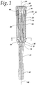
- FIG. 1 is a cross-sectional view of a teat cup assembly 16, in accordance with the present invention, including a shell 18 and a shell liner 22.
- the shell liner 22 includes a mouthpiece 24 defining a teat opening 26, a barrel 28 joined to the mouthpiece 24 and extending downwardly as depicted, an upper locking ring 30, and a lower locking ring 32 spaced apart from the upper locking ring to define a shell-engaging annular recess 36.
- the upper locking ring 30 defines a number of alignment recesses 40.
- the liner 22 can also include an integral short milk tube 41 joined to the barrel 28 and having a teat claw connecting end 43.
- the short milk tube 41 is an optional extension of the liner 22, and in other embodiments, the short milk tube 41 can be a separate item that connects to a lower end of the liner 22.
- the shell 18 includes an upper end 44, an upper opening 46, a lower end 48 defining a lower opening 50 with an inwardly directed annular edge 51, and keys 52 that are provided in a number, size, and arrangement to mate with the alignment recesses 40.
- the shell 18 also includes a pulsation connector 55.
- the liner 22 mouthpiece 24 can be of a type and shape described and depicted in U.S. Patent 8,113,145 , which is incorporated herein by reference, but other mouthpiece shapes and sizes can be used with the present invention.
- the mouthpiece 24 generally includes and upper surface 54 that interfaces with a teat and udder of a dairy animal to form a comfortable seal that minimizes loss of vacuum from the inside of the liner through the teat opening 26.
- the mouthpiece 24 further includes a downwardly extending skirt 56 that extends downward and is spaced apart from the barrel 28 so that an upper end of the shell (described below) can fit between the barrel 28 and the mouthpiece skirt 56, when assembled.
- the mouthpiece skirt 56 can include an alignment mark 58 to aid in assembly.
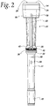
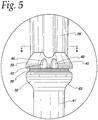
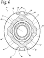
- the barrel 28 defines a longitudinal axis 62 ( Figs. 1 , 6 , and 7 ) and the barrel 28, itself, can have any desired cross-sectional shape including, round, oval, triangular, square, and the shape illustrated in Figs. 1 , 2 , and 5 , for example.
- barrel 28 shape is selected to optimize animal comfort and milking efficiency.
- the barrel 28 illustrated herein has walls 57 and corners 59 (see Fig. 5 , for example) that can be of uniform thickness or have varied thicknesses to control collapse of the barrel wall during pulsation and milking or for simplifying manufacturing. Any desired barrel cross-sectional shape can be used with the present invention.
- the upper locking ring 30 (sometimes referred to as a "hackle” in the dairy industry) is part of the barrel 28, and is preferably used in the present invention together with the lower locking ring 32 to define the annular recess 36.
- the liner 22 is joined to the shell lower opening 50 at the inwardly directed annular edge 51 using the annular recess 36. (See Figs. 1 and 7 .)
- This arrangement provides a secure connection between the liner 22 and shell 18, and due to friction, inhibits some level of twisting of the barrel 28 and the liner 22 relative to the shell 18. Nonetheless, twisting can still occur, so the barrel 28, and particularly the upper locking ring 30 of the liner 22, preferably defines two pairs of alignment recesses 40 to be engaged by the mating keys 52, in the shell 18.
- the alignment recesses 40 can be formed in any part of the barrel 28, but preferably in the lower end of the barrel 28.
- the alignment recesses 40 are formed integrally or are cut or otherwise formed in the upper locking ring 30.
- the upper locking ring 30 defines the alignment recesses 40 as a generally inverted U-shape with rounded shoulders 60 to enable a smoother assembly of the shell keys 52 into the alignment recesses 40.
- the alignment recesses 40 open to the annular recess 36, as illustrated.
- the alignment recess 40 should be radially spaced apart from a longitudinal axis of the barrel 28.
- the drawings illustrate the alignment recesses 40 in two pairs with one pair on a diametrically opposed side from the other. Although the illustrated arrangement is preferred, other arrangements of alignment recesses 40 are possible. For example, a single alignment recess 40 can be used on an asymmetrical arrangement, particularly if a particular orientation of the liner 22 relative to the shell 18 is desired.
- the shell keys 52 can be provided to match the number of alignment recesses 40, or relatively fewer keys 52 can be provided. For example, two alignment recesses 40 and one key 52 can be used to make it easier to assemble the liner 22 into the shell 18.
- the lower locking ring 32 preferably includes a rounded surface 63 against which the inwardly directed annular edge 51 of the lower end of the shell 18 will slide when the liner 22 is being installed in the shell 18.
- the inwardly directed annular edge 51 is releasably engaged with the liner's annular recess 36.
- it is preferably tensioned somewhat along the longitudinal axis 62, due to the relative size of the shell 18 and the liner 22. This is sometimes referred to as "pretensioning" and it improves liner performance.
- the short milk tube 41 can define an alignment feature 66 raised above, which is seen as a vertical embossment on the short milk tube 41 in Fig. 2 .
- An air vent 68 can also be provided and its location relative to other milker unit components can be controlled using the present invention, if desired.
- the liner is made of silicone, but any other suitable liner material can be used.
Landscapes
- Life Sciences & Earth Sciences (AREA)
- Animal Husbandry (AREA)
- Environmental Sciences (AREA)
- External Artificial Organs (AREA)
- Dairy Products (AREA)
- Medicines Containing Material From Animals Or Micro-Organisms (AREA)
Claims (18)
- Manchon (22) de faisceau trayeur comprenant : une embouchure (24) définissant une ouverture pour trayon (26) ; et
un corps (28) raccordé à l'embouchure (24), et définissant un orifice et un axe longitudinal (62) aligné avec l'ouverture pour trayon (26) ;
le corps (28) comprenant :un anneau de blocage inférieur (32) raccordé à une partie inférieure du corps (28) et s'étendant radialement vers l'extérieur à partir du corps (28) ; etun anneau de blocage supérieur (30) raccordé à la partie inférieure du corps (28), s'étendant radialement vers l'extérieur à partir du corps (28), et espacé de l'anneau de blocage inférieur (32) de façon à définir un renfoncement annulaire (36),caractérisé en ce que le corps (28) définit un renfoncement d'alignement (40) espacé radialement de l'axe longitudinal (62) et avec lequel une clavette d'étui (52) est destinée à venir en prise et en ce que le renfoncement d'alignement (40) est formé dans l'anneau de blocage supérieur (30). - Manchon pour étui de faisceau trayeur selon la revendication 1, dans lequel le renfoncement d'alignement (40) s'ouvre radialement vers l'extérieur.
- Manchon pour étui de faisceau trayeur selon la revendication 1, dans lequel le renfoncement d'alignement (40) est ouvert en direction du renfoncement annulaire (36).
- Manchon pour étui de faisceau trayeur selon la revendication 1, dans lequel le renfoncement d'alignement (40) s'ouvre radialement vers l'extérieur et dans le renfoncement annulaire (36).
- Manchon pour étui de faisceau trayeur selon la revendication 1, et le corps (28) définit en outre un second renfoncement d'alignement espacé du renfoncement d'alignement (40).
- Manchon pour étui de faisceau trayeur selon la revendication 1, et le corps (28) définit en outre :un second renfoncement d'alignement espacé du renfoncement d'alignement (40) de façon à former une première paire de renfoncements d'alignement ; etune seconde paire de renfoncements d'alignement espacée de la première paire de renfoncements d'alignement.
- Manchon pour étui de faisceau trayeur selon la revendication 1, et le corps (28) définit en outre :un second renfoncement d'alignement espacé du renfoncement d'alignement (40) de façon à former une première paire de renfoncements d'alignement ; etune seconde paire de renfoncements d'alignement espacée de manière diamétralement opposée vis-à-vis de la première paire de renfoncements d'alignement.
- Manchon pour étui de faisceau trayeur selon la revendication 1, et comprenant en outre :
un tuyau court à lait (41) raccordé au corps (28) et définissant un orifice à lait essentiellement aligné avec l'orifice du corps. - Manchon pour étui de faisceau trayeur selon la revendication 1, et comprenant en outre :
un tuyau court à lait (41) raccordé au corps (28) et définissant un orifice à lait essentiellement aligné avec l'orifice du corps, et définissant un évent (68). - Faisceau trayeur (16) comprenant :un manchon (22) selon la revendication 1,un étui (18) dans lequel est disposé le manchon (22) d'étui, et l'étui (18) définit une ouverture inférieure (50) comportant un bord (51) annulaire orienté vers l'intérieur disposé dans le renfoncement annulaire (36) entre l'anneau de blocage inférieur (32) et l'anneau de blocage supérieur (30) dans le manchon (22) d'étui, et l'étui (18) comprend une clavette (52) disposée dans le renfoncement d'alignement (40).
- Faisceau trayeur selon la revendication 10, dans lequel le renfoncement d'alignement (40) s'ouvre radialement vers l'extérieur.
- Faisceau trayeur selon la revendication 10, dans lequel le renfoncement d'alignement (40) est ouvert en direction du renfoncement annulaire (36).
- Faisceau trayeur selon la revendication 10, dans lequel le renfoncement d'alignement (40) s'ouvre radialement vers l'extérieur et dans le renfoncement annulaire (36).
- Faisceau trayeur selon la revendication 10, et l'anneau de blocage supérieur (30) définit en outre un second renfoncement d'alignement espacé du renfoncement d'alignement (40).
- Faisceau trayeur selon la revendication 10, et l'anneau de blocage supérieur (30) définit en outre :un second renfoncement d'alignement espacé du renfoncement d'alignement (40) de façon à former une première paire de renfoncements d'alignement ; etune seconde paire de renfoncements d'alignement espacée de la première paire de renfoncements d'alignement.
- Faisceau trayeur selon la revendication 10, et l'anneau de blocage supérieur (30) définit en outre :un second renfoncement d'alignement espacé du renfoncement d'alignement (40) de façon à former une première paire de renfoncements d'alignement ; etune seconde paire de renfoncements d'alignement espacée de manière diamétralement opposée vis-à-vis de la première paire de renfoncements d'alignement.
- Faisceau trayeur selon la revendication 10, et comprenant en outre :
un tuyau court à lait (41) raccordé au corps (28) et définissant un orifice à lait essentiellement aligné avec l'orifice du corps. - Faisceau trayeur selon la revendication 10, et comprenant en outre :
un tuyau court à lait (41) raccordé au corps (28) et définissant un orifice à lait essentiellement aligné avec l'orifice du corps, et définissant un évent (68).
Priority Applications (1)
| Application Number | Priority Date | Filing Date | Title |
|---|---|---|---|
| EP18185175.9A EP3461329B1 (fr) | 2013-09-27 | 2014-09-09 | Manchon et cylindre anti-torsion pour ensemble gobelet trayeur pour animal laitier |
Applications Claiming Priority (2)
| Application Number | Priority Date | Filing Date | Title |
|---|---|---|---|
| US14/039,998 US20150090183A1 (en) | 2013-09-27 | 2013-09-27 | Anti-twist Liner and Shell for a Dairy Animal Teat Cup Assembly |
| PCT/US2014/054681 WO2015047714A1 (fr) | 2013-09-27 | 2014-09-09 | Manchon et cylindre anti-torsion pour ensemble gobelet trayeur pour animal laitier |
Related Child Applications (1)
| Application Number | Title | Priority Date | Filing Date |
|---|---|---|---|
| EP18185175.9A Division EP3461329B1 (fr) | 2013-09-27 | 2014-09-09 | Manchon et cylindre anti-torsion pour ensemble gobelet trayeur pour animal laitier |
Publications (2)
| Publication Number | Publication Date |
|---|---|
| EP3048875A1 EP3048875A1 (fr) | 2016-08-03 |
| EP3048875B1 true EP3048875B1 (fr) | 2018-07-25 |
Family
ID=51589535
Family Applications (2)
| Application Number | Title | Priority Date | Filing Date |
|---|---|---|---|
| EP18185175.9A Active EP3461329B1 (fr) | 2013-09-27 | 2014-09-09 | Manchon et cylindre anti-torsion pour ensemble gobelet trayeur pour animal laitier |
| EP14772022.1A Active EP3048875B1 (fr) | 2013-09-27 | 2014-09-09 | Manchon et cylindre anti-torsion pour ensemble gobelet trayeur pour animal laitier |
Family Applications Before (1)
| Application Number | Title | Priority Date | Filing Date |
|---|---|---|---|
| EP18185175.9A Active EP3461329B1 (fr) | 2013-09-27 | 2014-09-09 | Manchon et cylindre anti-torsion pour ensemble gobelet trayeur pour animal laitier |
Country Status (6)
| Country | Link |
|---|---|
| US (2) | US20150090183A1 (fr) |
| EP (2) | EP3461329B1 (fr) |
| CN (1) | CN105705008A (fr) |
| ES (2) | ES2921905T3 (fr) |
| RU (2) | RU2672495C2 (fr) |
| WO (1) | WO2015047714A1 (fr) |
Cited By (1)
| Publication number | Priority date | Publication date | Assignee | Title |
|---|---|---|---|---|
| US11510389B2 (en) | 2013-09-27 | 2022-11-29 | Gea Farm Technologies, Inc. | Anti-twist liner and shell for a dairy animal teat cup assembly |
Families Citing this family (8)
| Publication number | Priority date | Publication date | Assignee | Title |
|---|---|---|---|---|
| DE102014101613A1 (de) * | 2014-02-10 | 2015-08-13 | Happel WDA Besitz GbR (vertretungsberechtigter Gesellschafter: Werner Happel, 87654 Friesenried) | Zitzengummi |
| US9992967B2 (en) | 2015-12-14 | 2018-06-12 | Delaval Holding Ab | Secure collapse teatcup liner |
| BR112018072600B1 (pt) * | 2016-05-04 | 2022-04-19 | Delaval Holding Ab | Um cartucho para uma teteira, e uma teteira |
| BR112020007985A2 (pt) * | 2017-10-26 | 2020-10-20 | Delaval Holding Ab | um cartucho configurado para formar uma parte de uma teteira, e uma teteira |
| GB201902189D0 (en) * | 2019-02-18 | 2019-04-03 | Avon Polymer Prod Ltd | Milking apparatus |
| DE102021115078B4 (de) * | 2021-06-11 | 2023-01-26 | Jakob Maier und Wilfried Hatzack Erfinder GbR (vertretungsberechtigte Gesellschafter: Jakob Maier, 86842 Türkheim und Wilfried Hatzack, 86842 Türkheim) | Elastischer Melkbechereinsatz mit erweiterter Funktionalität |
| USD1057325S1 (en) | 2022-01-14 | 2025-01-07 | Gea Farm Technologies, Inc. | Short milk tube vent plug for a dairy animal milker unit |
| USD1024461S1 (en) | 2022-03-15 | 2024-04-23 | Gea Farm Technologies Gmbh | Teat cup liner head for milking machines |
Family Cites Families (40)
| Publication number | Priority date | Publication date | Assignee | Title |
|---|---|---|---|---|
| US1020258A (en) | 1911-08-30 | 1912-03-12 | Jesse Harper Bundy | Swivel-joint hose-coupling. |
| US3096740A (en) * | 1961-08-25 | 1963-07-09 | Noorlander Daniel Olie | Teat cup liner construction |
| US4269143A (en) * | 1977-09-16 | 1981-05-26 | Dec International, Inc. | Teat cup assembly |
| CA1179289A (fr) * | 1982-05-07 | 1984-12-11 | Nu Pulse New Zealand Limited | Trayeuse |
| US4604969A (en) * | 1985-06-17 | 1986-08-12 | Larson Leigh R | Milking inflation including air vent |
| US4913471A (en) | 1987-11-10 | 1990-04-03 | Huneke Gerald L | Swivel joint |
| US5069162A (en) * | 1990-05-23 | 1991-12-03 | Dec International, Inc. | Teat cup inflation |
| US5572947A (en) * | 1995-03-29 | 1996-11-12 | Hi-Life Rubber Inc. | Milking inflation |
| SE506122C2 (sv) * | 1996-03-27 | 1997-11-10 | Alfa Laval Agri Ab | Spenkopp med ventilhus |
| ES2217746T3 (es) * | 1998-03-23 | 2004-11-01 | Silclear Limited | Funda de pezonera. |
| US6055931A (en) * | 1998-10-13 | 2000-05-02 | Dec International, Inc. | Clog resistant air vent plug for teatcup liner |
| SE514503C2 (sv) * | 1999-06-10 | 2001-03-05 | Delaval Holding Ab | Spengummi, spenkopp och mjölkningsorgan |
| US6899055B2 (en) * | 1999-06-10 | 2005-05-31 | Delaval Holding Ab | Teatcup liner, a teatcup and a milking member |
| US6435132B1 (en) * | 1999-12-23 | 2002-08-20 | Constance J. Milbrath | Teat cup assembly |
| DE10018870C2 (de) * | 2000-04-14 | 2002-02-21 | Kathrin Lincke | Zitzengummi |
| DE10215437A1 (de) * | 2002-04-08 | 2003-10-16 | Fritz Happel | Düse mit Reinigungsnadel |
| SE0203871D0 (sv) * | 2002-12-20 | 2002-12-20 | Delaval Holding Ab | Milking Devices |
| US6997136B1 (en) * | 2003-03-21 | 2006-02-14 | Avon Hi-Life, Inc. | Teat cup assembly |
| CA2467156C (fr) | 2003-05-12 | 2012-07-17 | Jin-Woong Shin | Revetement de sol coussine et methodes de fabrication et d'installation |
| US20050155209A1 (en) * | 2004-01-20 | 2005-07-21 | Flexmaster Canada Limited | Positive pipe interlock |
| SE527508C2 (sv) * | 2004-06-10 | 2006-03-28 | Delaval Holding Ab | Spengummi och spenkopp |
| US7290498B2 (en) | 2004-06-29 | 2007-11-06 | Lauren Agrisystems, Ltd. | Vent plug for milking liner |
| CA2570327C (fr) | 2004-06-29 | 2013-11-26 | Lauren Agrisystems, Ltd. | Manchon de gobelet-trayeur |
| US7293527B2 (en) | 2004-06-29 | 2007-11-13 | Lauren Agrisystems, Ltd. | Vent plug for milking liner |
| USD552306S1 (en) | 2005-10-15 | 2007-10-02 | Lauren Agrisystems, Ltd. | Hoof block |
| DE102005055973B4 (de) | 2005-11-22 | 2010-02-04 | Gea Westfaliasurge Gmbh | Melkbecher und Melkverfahren |
| SE529994C2 (sv) * | 2006-05-31 | 2008-02-05 | Delaval Holding Ab | Spenkopp |
| SE531555C2 (sv) * | 2007-05-22 | 2009-05-19 | Delaval Holding Ab | Ett slangelement |
| US7975647B2 (en) | 2007-09-22 | 2011-07-12 | Lauren Agrisystems, Ltd. | Flow restrictor for milking apparatus |
| US8113145B2 (en) * | 2007-09-27 | 2012-02-14 | Gea Farm Technologies, Inc. | Teat cup liner |
| EP2083167B1 (fr) * | 2008-01-23 | 2017-05-10 | Continental Automotive GmbH | Agencement de couplage et ensemble de connexion |
| DE102008046098A1 (de) * | 2008-09-05 | 2010-06-24 | Lactocorder Ag | Schlauchkupplung |
| US9810358B2 (en) * | 2009-02-03 | 2017-11-07 | Aqseptence Group, Inc. | Male push lock pipe connection system |
| US8302561B2 (en) | 2009-08-11 | 2012-11-06 | Lauren Agrisystems, Ltd. | Teat cup shell |
| NZ599630A (en) * | 2009-12-02 | 2013-10-25 | Avon Polymer Prod Ltd | Mouthpiece-vented teat cup inflation |
| US8056505B2 (en) | 2009-12-08 | 2011-11-15 | Lauren Agrisystems, Ltd. | Vent for milking liner |
| WO2012071000A1 (fr) * | 2010-11-22 | 2012-05-31 | Delaval Holding Ab | Manchon-trayeur et gobelet trayeur |
| CA2859959C (fr) * | 2011-12-22 | 2019-11-05 | Delaval Holding Ab | Raccord et gobelet trayeur |
| US9288962B2 (en) * | 2012-11-02 | 2016-03-22 | Steven Brent Priest | Low-slip high-capacity teat cup liner |
| US20150090183A1 (en) | 2013-09-27 | 2015-04-02 | Gea Farm Technologies, Inc. | Anti-twist Liner and Shell for a Dairy Animal Teat Cup Assembly |
-
2013
- 2013-09-27 US US14/039,998 patent/US20150090183A1/en not_active Abandoned
-
2014
- 2014-09-09 WO PCT/US2014/054681 patent/WO2015047714A1/fr not_active Ceased
- 2014-09-09 ES ES18185175T patent/ES2921905T3/es active Active
- 2014-09-09 RU RU2016110585A patent/RU2672495C2/ru active
- 2014-09-09 EP EP18185175.9A patent/EP3461329B1/fr active Active
- 2014-09-09 ES ES14772022.1T patent/ES2692272T3/es active Active
- 2014-09-09 RU RU2018138970A patent/RU2769353C2/ru active
- 2014-09-09 CN CN201480052741.2A patent/CN105705008A/zh active Pending
- 2014-09-09 EP EP14772022.1A patent/EP3048875B1/fr active Active
-
2020
- 2020-09-08 US US17/014,053 patent/US11510389B2/en active Active
Non-Patent Citations (1)
| Title |
|---|
| None * |
Cited By (1)
| Publication number | Priority date | Publication date | Assignee | Title |
|---|---|---|---|---|
| US11510389B2 (en) | 2013-09-27 | 2022-11-29 | Gea Farm Technologies, Inc. | Anti-twist liner and shell for a dairy animal teat cup assembly |
Also Published As
| Publication number | Publication date |
|---|---|
| NZ756664A (en) | 2020-12-18 |
| US20150090183A1 (en) | 2015-04-02 |
| RU2018138970A (ru) | 2019-03-21 |
| ES2921905T3 (es) | 2022-09-02 |
| RU2016110585A3 (fr) | 2018-04-28 |
| NZ756661A (en) | 2020-12-18 |
| RU2016110585A (ru) | 2017-11-01 |
| CN105705008A (zh) | 2016-06-22 |
| RU2672495C2 (ru) | 2018-11-15 |
| US11510389B2 (en) | 2022-11-29 |
| RU2769353C2 (ru) | 2022-03-30 |
| ES2692272T3 (es) | 2018-12-03 |
| EP3461329B1 (fr) | 2022-04-27 |
| RU2018138970A3 (fr) | 2021-12-21 |
| EP3461329A1 (fr) | 2019-04-03 |
| US20200396954A1 (en) | 2020-12-24 |
| WO2015047714A1 (fr) | 2015-04-02 |
| NZ717977A (en) | 2020-12-18 |
| EP3048875A1 (fr) | 2016-08-03 |
Similar Documents
| Publication | Publication Date | Title |
|---|---|---|
| EP3048875B1 (fr) | Manchon et cylindre anti-torsion pour ensemble gobelet trayeur pour animal laitier | |
| US10785952B2 (en) | Short milk tube with protective vent for a dairy animal milker unit | |
| EP0958738B1 (fr) | Manchon trayeur avec vide désiré dans l'embouchure | |
| WO2009042022A1 (fr) | Manchon de gobelet-trayeur | |
| CN102655738B (zh) | 接口件通气的挤奶杯内套 | |
| US12178185B2 (en) | Short milk tube vent plug for a dairy animal milker unit | |
| US6742475B1 (en) | Variable shut off teat cup liner | |
| JP2019514363A (ja) | 乳頭カップのためのカートリッジ及び乳頭カップ | |
| US9992967B2 (en) | Secure collapse teatcup liner | |
| NZ717977B2 (en) | Anti-twist liner and shell for a dairy animal teat cup assembly | |
| NZ756661B2 (en) | Anti-twist liner and shell for a dairy animal teat cup assembly | |
| NZ756664B2 (en) | Anti-twist liner and shell for a dairy animal teat cup assembly | |
| WO2017105321A1 (fr) | Manchon trayeur à affaissement stable | |
| EP3706555B1 (fr) | Manchon trayeur et gobelet trayeur | |
| EA042182B1 (ru) | Короткая молочная трубка с защищенным вентиляционным отверстием аппарата для доения молочных животных |
Legal Events
| Date | Code | Title | Description |
|---|---|---|---|
| PUAI | Public reference made under article 153(3) epc to a published international application that has entered the european phase |
Free format text: ORIGINAL CODE: 0009012 |
|
| 17P | Request for examination filed |
Effective date: 20160408 |
|
| AK | Designated contracting states |
Kind code of ref document: A1 Designated state(s): AL AT BE BG CH CY CZ DE DK EE ES FI FR GB GR HR HU IE IS IT LI LT LU LV MC MK MT NL NO PL PT RO RS SE SI SK SM TR |
|
| AX | Request for extension of the european patent |
Extension state: BA ME |
|
| DAX | Request for extension of the european patent (deleted) | ||
| STAA | Information on the status of an ep patent application or granted ep patent |
Free format text: STATUS: EXAMINATION IS IN PROGRESS |
|
| 17Q | First examination report despatched |
Effective date: 20170511 |
|
| RIC1 | Information provided on ipc code assigned before grant |
Ipc: A01J 5/06 20060101ALI20180110BHEP Ipc: A01J 5/08 20060101AFI20180110BHEP |
|
| GRAP | Despatch of communication of intention to grant a patent |
Free format text: ORIGINAL CODE: EPIDOSNIGR1 |
|
| STAA | Information on the status of an ep patent application or granted ep patent |
Free format text: STATUS: GRANT OF PATENT IS INTENDED |
|
| INTG | Intention to grant announced |
Effective date: 20180216 |
|
| GRAS | Grant fee paid |
Free format text: ORIGINAL CODE: EPIDOSNIGR3 |
|
| GRAA | (expected) grant |
Free format text: ORIGINAL CODE: 0009210 |
|
| STAA | Information on the status of an ep patent application or granted ep patent |
Free format text: STATUS: THE PATENT HAS BEEN GRANTED |
|
| AK | Designated contracting states |
Kind code of ref document: B1 Designated state(s): AL AT BE BG CH CY CZ DE DK EE ES FI FR GB GR HR HU IE IS IT LI LT LU LV MC MK MT NL NO PL PT RO RS SE SI SK SM TR |
|
| REG | Reference to a national code |
Ref country code: GB Ref legal event code: FG4D |
|
| REG | Reference to a national code |
Ref country code: CH Ref legal event code: EP |
|
| REG | Reference to a national code |
Ref country code: AT Ref legal event code: REF Ref document number: 1020788 Country of ref document: AT Kind code of ref document: T Effective date: 20180815 |
|
| REG | Reference to a national code |
Ref country code: IE Ref legal event code: FG4D |
|
| REG | Reference to a national code |
Ref country code: DE Ref legal event code: R096 Ref document number: 602014029206 Country of ref document: DE |
|
| REG | Reference to a national code |
Ref country code: NL Ref legal event code: MP Effective date: 20180725 |
|
| REG | Reference to a national code |
Ref country code: ES Ref legal event code: FG2A Ref document number: 2692272 Country of ref document: ES Kind code of ref document: T3 Effective date: 20181203 |
|
| REG | Reference to a national code |
Ref country code: LT Ref legal event code: MG4D |
|
| PG25 | Lapsed in a contracting state [announced via postgrant information from national office to epo] |
Ref country code: NL Free format text: LAPSE BECAUSE OF FAILURE TO SUBMIT A TRANSLATION OF THE DESCRIPTION OR TO PAY THE FEE WITHIN THE PRESCRIBED TIME-LIMIT Effective date: 20180725 |
|
| REG | Reference to a national code |
Ref country code: AT Ref legal event code: MK05 Ref document number: 1020788 Country of ref document: AT Kind code of ref document: T Effective date: 20180725 |
|
| PG25 | Lapsed in a contracting state [announced via postgrant information from national office to epo] |
Ref country code: AT Free format text: LAPSE BECAUSE OF FAILURE TO SUBMIT A TRANSLATION OF THE DESCRIPTION OR TO PAY THE FEE WITHIN THE PRESCRIBED TIME-LIMIT Effective date: 20180725 Ref country code: SE Free format text: LAPSE BECAUSE OF FAILURE TO SUBMIT A TRANSLATION OF THE DESCRIPTION OR TO PAY THE FEE WITHIN THE PRESCRIBED TIME-LIMIT Effective date: 20180725 Ref country code: BG Free format text: LAPSE BECAUSE OF FAILURE TO SUBMIT A TRANSLATION OF THE DESCRIPTION OR TO PAY THE FEE WITHIN THE PRESCRIBED TIME-LIMIT Effective date: 20181025 Ref country code: IS Free format text: LAPSE BECAUSE OF FAILURE TO SUBMIT A TRANSLATION OF THE DESCRIPTION OR TO PAY THE FEE WITHIN THE PRESCRIBED TIME-LIMIT Effective date: 20181125 Ref country code: GR Free format text: LAPSE BECAUSE OF FAILURE TO SUBMIT A TRANSLATION OF THE DESCRIPTION OR TO PAY THE FEE WITHIN THE PRESCRIBED TIME-LIMIT Effective date: 20181026 Ref country code: NO Free format text: LAPSE BECAUSE OF FAILURE TO SUBMIT A TRANSLATION OF THE DESCRIPTION OR TO PAY THE FEE WITHIN THE PRESCRIBED TIME-LIMIT Effective date: 20181025 Ref country code: FI Free format text: LAPSE BECAUSE OF FAILURE TO SUBMIT A TRANSLATION OF THE DESCRIPTION OR TO PAY THE FEE WITHIN THE PRESCRIBED TIME-LIMIT Effective date: 20180725 Ref country code: RS Free format text: LAPSE BECAUSE OF FAILURE TO SUBMIT A TRANSLATION OF THE DESCRIPTION OR TO PAY THE FEE WITHIN THE PRESCRIBED TIME-LIMIT Effective date: 20180725 Ref country code: PL Free format text: LAPSE BECAUSE OF FAILURE TO SUBMIT A TRANSLATION OF THE DESCRIPTION OR TO PAY THE FEE WITHIN THE PRESCRIBED TIME-LIMIT Effective date: 20180725 Ref country code: LT Free format text: LAPSE BECAUSE OF FAILURE TO SUBMIT A TRANSLATION OF THE DESCRIPTION OR TO PAY THE FEE WITHIN THE PRESCRIBED TIME-LIMIT Effective date: 20180725 |
|
| PG25 | Lapsed in a contracting state [announced via postgrant information from national office to epo] |
Ref country code: HR Free format text: LAPSE BECAUSE OF FAILURE TO SUBMIT A TRANSLATION OF THE DESCRIPTION OR TO PAY THE FEE WITHIN THE PRESCRIBED TIME-LIMIT Effective date: 20180725 Ref country code: AL Free format text: LAPSE BECAUSE OF FAILURE TO SUBMIT A TRANSLATION OF THE DESCRIPTION OR TO PAY THE FEE WITHIN THE PRESCRIBED TIME-LIMIT Effective date: 20180725 Ref country code: LV Free format text: LAPSE BECAUSE OF FAILURE TO SUBMIT A TRANSLATION OF THE DESCRIPTION OR TO PAY THE FEE WITHIN THE PRESCRIBED TIME-LIMIT Effective date: 20180725 |
|
| REG | Reference to a national code |
Ref country code: DE Ref legal event code: R097 Ref document number: 602014029206 Country of ref document: DE |
|
| PG25 | Lapsed in a contracting state [announced via postgrant information from national office to epo] |
Ref country code: RO Free format text: LAPSE BECAUSE OF FAILURE TO SUBMIT A TRANSLATION OF THE DESCRIPTION OR TO PAY THE FEE WITHIN THE PRESCRIBED TIME-LIMIT Effective date: 20180725 Ref country code: CZ Free format text: LAPSE BECAUSE OF FAILURE TO SUBMIT A TRANSLATION OF THE DESCRIPTION OR TO PAY THE FEE WITHIN THE PRESCRIBED TIME-LIMIT Effective date: 20180725 Ref country code: MC Free format text: LAPSE BECAUSE OF FAILURE TO SUBMIT A TRANSLATION OF THE DESCRIPTION OR TO PAY THE FEE WITHIN THE PRESCRIBED TIME-LIMIT Effective date: 20180725 Ref country code: EE Free format text: LAPSE BECAUSE OF FAILURE TO SUBMIT A TRANSLATION OF THE DESCRIPTION OR TO PAY THE FEE WITHIN THE PRESCRIBED TIME-LIMIT Effective date: 20180725 |
|
| REG | Reference to a national code |
Ref country code: CH Ref legal event code: PL |
|
| PG25 | Lapsed in a contracting state [announced via postgrant information from national office to epo] |
Ref country code: SK Free format text: LAPSE BECAUSE OF FAILURE TO SUBMIT A TRANSLATION OF THE DESCRIPTION OR TO PAY THE FEE WITHIN THE PRESCRIBED TIME-LIMIT Effective date: 20180725 Ref country code: DK Free format text: LAPSE BECAUSE OF FAILURE TO SUBMIT A TRANSLATION OF THE DESCRIPTION OR TO PAY THE FEE WITHIN THE PRESCRIBED TIME-LIMIT Effective date: 20180725 Ref country code: SM Free format text: LAPSE BECAUSE OF FAILURE TO SUBMIT A TRANSLATION OF THE DESCRIPTION OR TO PAY THE FEE WITHIN THE PRESCRIBED TIME-LIMIT Effective date: 20180725 |
|
| PLBE | No opposition filed within time limit |
Free format text: ORIGINAL CODE: 0009261 |
|
| STAA | Information on the status of an ep patent application or granted ep patent |
Free format text: STATUS: NO OPPOSITION FILED WITHIN TIME LIMIT |
|
| REG | Reference to a national code |
Ref country code: BE Ref legal event code: MM Effective date: 20180930 |
|
| GBPC | Gb: european patent ceased through non-payment of renewal fee |
Effective date: 20181025 |
|
| REG | Reference to a national code |
Ref country code: IE Ref legal event code: MM4A |
|
| PG25 | Lapsed in a contracting state [announced via postgrant information from national office to epo] |
Ref country code: LU Free format text: LAPSE BECAUSE OF NON-PAYMENT OF DUE FEES Effective date: 20180909 |
|
| 26N | No opposition filed |
Effective date: 20190426 |
|
| PG25 | Lapsed in a contracting state [announced via postgrant information from national office to epo] |
Ref country code: IE Free format text: LAPSE BECAUSE OF NON-PAYMENT OF DUE FEES Effective date: 20180909 |
|
| PG25 | Lapsed in a contracting state [announced via postgrant information from national office to epo] |
Ref country code: LI Free format text: LAPSE BECAUSE OF NON-PAYMENT OF DUE FEES Effective date: 20180930 Ref country code: FR Free format text: LAPSE BECAUSE OF NON-PAYMENT OF DUE FEES Effective date: 20180925 Ref country code: BE Free format text: LAPSE BECAUSE OF NON-PAYMENT OF DUE FEES Effective date: 20180930 Ref country code: SI Free format text: LAPSE BECAUSE OF FAILURE TO SUBMIT A TRANSLATION OF THE DESCRIPTION OR TO PAY THE FEE WITHIN THE PRESCRIBED TIME-LIMIT Effective date: 20180725 Ref country code: CH Free format text: LAPSE BECAUSE OF NON-PAYMENT OF DUE FEES Effective date: 20180930 |
|
| PG25 | Lapsed in a contracting state [announced via postgrant information from national office to epo] |
Ref country code: GB Free format text: LAPSE BECAUSE OF NON-PAYMENT OF DUE FEES Effective date: 20181025 |
|
| PG25 | Lapsed in a contracting state [announced via postgrant information from national office to epo] |
Ref country code: MT Free format text: LAPSE BECAUSE OF NON-PAYMENT OF DUE FEES Effective date: 20180909 |
|
| PG25 | Lapsed in a contracting state [announced via postgrant information from national office to epo] |
Ref country code: TR Free format text: LAPSE BECAUSE OF FAILURE TO SUBMIT A TRANSLATION OF THE DESCRIPTION OR TO PAY THE FEE WITHIN THE PRESCRIBED TIME-LIMIT Effective date: 20180725 |
|
| PG25 | Lapsed in a contracting state [announced via postgrant information from national office to epo] |
Ref country code: PT Free format text: LAPSE BECAUSE OF FAILURE TO SUBMIT A TRANSLATION OF THE DESCRIPTION OR TO PAY THE FEE WITHIN THE PRESCRIBED TIME-LIMIT Effective date: 20180725 |
|
| PG25 | Lapsed in a contracting state [announced via postgrant information from national office to epo] |
Ref country code: CY Free format text: LAPSE BECAUSE OF FAILURE TO SUBMIT A TRANSLATION OF THE DESCRIPTION OR TO PAY THE FEE WITHIN THE PRESCRIBED TIME-LIMIT Effective date: 20180725 Ref country code: HU Free format text: LAPSE BECAUSE OF FAILURE TO SUBMIT A TRANSLATION OF THE DESCRIPTION OR TO PAY THE FEE WITHIN THE PRESCRIBED TIME-LIMIT; INVALID AB INITIO Effective date: 20140909 Ref country code: MK Free format text: LAPSE BECAUSE OF NON-PAYMENT OF DUE FEES Effective date: 20180725 |
|
| P01 | Opt-out of the competence of the unified patent court (upc) registered |
Effective date: 20230523 |
|
| PGFP | Annual fee paid to national office [announced via postgrant information from national office to epo] |
Ref country code: IT Payment date: 20250929 Year of fee payment: 12 |
|
| PGFP | Annual fee paid to national office [announced via postgrant information from national office to epo] |
Ref country code: DE Payment date: 20251002 Year of fee payment: 12 |
|
| PGFP | Annual fee paid to national office [announced via postgrant information from national office to epo] |
Ref country code: ES Payment date: 20251001 Year of fee payment: 12 |