EP3048951B1 - Systèmes chirurgicaux de vitrectomie à détection de pression - Google Patents
Systèmes chirurgicaux de vitrectomie à détection de pression Download PDFInfo
- Publication number
- EP3048951B1 EP3048951B1 EP14865260.5A EP14865260A EP3048951B1 EP 3048951 B1 EP3048951 B1 EP 3048951B1 EP 14865260 A EP14865260 A EP 14865260A EP 3048951 B1 EP3048951 B1 EP 3048951B1
- Authority
- EP
- European Patent Office
- Prior art keywords
- pressure
- infusion line
- pressure sensors
- eye
- flexible elongate
- Prior art date
- Legal status (The legal status is an assumption and is not a legal conclusion. Google has not performed a legal analysis and makes no representation as to the accuracy of the status listed.)
- Not-in-force
Links
- 238000001802 infusion Methods 0.000 claims description 51
- 238000000034 method Methods 0.000 claims description 32
- 239000012530 fluid Substances 0.000 claims description 22
- 230000002262 irrigation Effects 0.000 claims description 8
- 238000003973 irrigation Methods 0.000 claims description 8
- 238000005259 measurement Methods 0.000 claims description 8
- 238000004891 communication Methods 0.000 claims description 7
- 230000008878 coupling Effects 0.000 claims description 4
- 238000010168 coupling process Methods 0.000 claims description 4
- 238000005859 coupling reaction Methods 0.000 claims description 4
- 238000005520 cutting process Methods 0.000 description 57
- 239000000523 sample Substances 0.000 description 57
- 210000004127 vitreous body Anatomy 0.000 description 14
- 238000009530 blood pressure measurement Methods 0.000 description 12
- 238000001356 surgical procedure Methods 0.000 description 12
- 230000004410 intraocular pressure Effects 0.000 description 10
- 239000000835 fiber Substances 0.000 description 5
- 238000012544 monitoring process Methods 0.000 description 5
- 210000001525 retina Anatomy 0.000 description 5
- 239000012528 membrane Substances 0.000 description 4
- 230000008859 change Effects 0.000 description 3
- 239000000463 material Substances 0.000 description 3
- 230000003287 optical effect Effects 0.000 description 3
- 208000002367 Retinal Perforations Diseases 0.000 description 2
- 206010038897 Retinal tear Diseases 0.000 description 2
- 230000003247 decreasing effect Effects 0.000 description 2
- 230000008569 process Effects 0.000 description 2
- 238000012545 processing Methods 0.000 description 2
- 210000003786 sclera Anatomy 0.000 description 2
- FAPWRFPIFSIZLT-UHFFFAOYSA-M Sodium chloride Chemical compound [Na+].[Cl-] FAPWRFPIFSIZLT-UHFFFAOYSA-M 0.000 description 1
- 210000003161 choroid Anatomy 0.000 description 1
- 230000007812 deficiency Effects 0.000 description 1
- 238000001514 detection method Methods 0.000 description 1
- 238000002224 dissection Methods 0.000 description 1
- 238000002637 fluid replacement therapy Methods 0.000 description 1
- 230000006870 function Effects 0.000 description 1
- 238000011065 in-situ storage Methods 0.000 description 1
- 239000007788 liquid Substances 0.000 description 1
- 230000001737 promoting effect Effects 0.000 description 1
- 238000000926 separation method Methods 0.000 description 1
- 239000011780 sodium chloride Substances 0.000 description 1
- 230000001960 triggered effect Effects 0.000 description 1
- 238000013022 venting Methods 0.000 description 1
- 230000000007 visual effect Effects 0.000 description 1
Images


Classifications
-
- A—HUMAN NECESSITIES
- A61—MEDICAL OR VETERINARY SCIENCE; HYGIENE
- A61F—FILTERS IMPLANTABLE INTO BLOOD VESSELS; PROSTHESES; DEVICES PROVIDING PATENCY TO, OR PREVENTING COLLAPSING OF, TUBULAR STRUCTURES OF THE BODY, e.g. STENTS; ORTHOPAEDIC, NURSING OR CONTRACEPTIVE DEVICES; FOMENTATION; TREATMENT OR PROTECTION OF EYES OR EARS; BANDAGES, DRESSINGS OR ABSORBENT PADS; FIRST-AID KITS
- A61F9/00—Methods or devices for treatment of the eyes; Devices for putting in contact-lenses; Devices to correct squinting; Apparatus to guide the blind; Protective devices for the eyes, carried on the body or in the hand
- A61F9/007—Methods or devices for eye surgery
- A61F9/00781—Apparatus for modifying intraocular pressure, e.g. for glaucoma treatment
-
- A—HUMAN NECESSITIES
- A61—MEDICAL OR VETERINARY SCIENCE; HYGIENE
- A61B—DIAGNOSIS; SURGERY; IDENTIFICATION
- A61B3/00—Apparatus for testing the eyes; Instruments for examining the eyes
- A61B3/10—Objective types, i.e. instruments for examining the eyes independent of the patients' perceptions or reactions
- A61B3/16—Objective types, i.e. instruments for examining the eyes independent of the patients' perceptions or reactions for measuring intraocular pressure, e.g. tonometers
-
- A—HUMAN NECESSITIES
- A61—MEDICAL OR VETERINARY SCIENCE; HYGIENE
- A61F—FILTERS IMPLANTABLE INTO BLOOD VESSELS; PROSTHESES; DEVICES PROVIDING PATENCY TO, OR PREVENTING COLLAPSING OF, TUBULAR STRUCTURES OF THE BODY, e.g. STENTS; ORTHOPAEDIC, NURSING OR CONTRACEPTIVE DEVICES; FOMENTATION; TREATMENT OR PROTECTION OF EYES OR EARS; BANDAGES, DRESSINGS OR ABSORBENT PADS; FIRST-AID KITS
- A61F9/00—Methods or devices for treatment of the eyes; Devices for putting in contact-lenses; Devices to correct squinting; Apparatus to guide the blind; Protective devices for the eyes, carried on the body or in the hand
- A61F9/007—Methods or devices for eye surgery
- A61F9/00736—Instruments for removal of intra-ocular material or intra-ocular injection, e.g. cataract instruments
- A61F9/00763—Instruments for removal of intra-ocular material or intra-ocular injection, e.g. cataract instruments with rotating or reciprocating cutting elements, e.g. concentric cutting needles
-
- A—HUMAN NECESSITIES
- A61—MEDICAL OR VETERINARY SCIENCE; HYGIENE
- A61M—DEVICES FOR INTRODUCING MEDIA INTO, OR ONTO, THE BODY; DEVICES FOR TRANSDUCING BODY MEDIA OR FOR TAKING MEDIA FROM THE BODY; DEVICES FOR PRODUCING OR ENDING SLEEP OR STUPOR
- A61M1/00—Suction or pumping devices for medical purposes; Devices for carrying-off, for treatment of, or for carrying-over, body-liquids; Drainage systems
- A61M1/71—Suction drainage systems
- A61M1/76—Handpieces
-
- A—HUMAN NECESSITIES
- A61—MEDICAL OR VETERINARY SCIENCE; HYGIENE
- A61M—DEVICES FOR INTRODUCING MEDIA INTO, OR ONTO, THE BODY; DEVICES FOR TRANSDUCING BODY MEDIA OR FOR TAKING MEDIA FROM THE BODY; DEVICES FOR PRODUCING OR ENDING SLEEP OR STUPOR
- A61M3/00—Medical syringes, e.g. enemata; Irrigators
- A61M3/02—Enemata; Irrigators
- A61M3/0202—Enemata; Irrigators with electronic control means or interfaces
-
- A—HUMAN NECESSITIES
- A61—MEDICAL OR VETERINARY SCIENCE; HYGIENE
- A61M—DEVICES FOR INTRODUCING MEDIA INTO, OR ONTO, THE BODY; DEVICES FOR TRANSDUCING BODY MEDIA OR FOR TAKING MEDIA FROM THE BODY; DEVICES FOR PRODUCING OR ENDING SLEEP OR STUPOR
- A61M3/00—Medical syringes, e.g. enemata; Irrigators
- A61M3/02—Enemata; Irrigators
- A61M3/0204—Physical characteristics of the irrigation fluid, e.g. conductivity or turbidity
- A61M3/0208—Physical characteristics of the irrigation fluid, e.g. conductivity or turbidity before use
-
- A—HUMAN NECESSITIES
- A61—MEDICAL OR VETERINARY SCIENCE; HYGIENE
- A61M—DEVICES FOR INTRODUCING MEDIA INTO, OR ONTO, THE BODY; DEVICES FOR TRANSDUCING BODY MEDIA OR FOR TAKING MEDIA FROM THE BODY; DEVICES FOR PRODUCING OR ENDING SLEEP OR STUPOR
- A61M3/00—Medical syringes, e.g. enemata; Irrigators
- A61M3/02—Enemata; Irrigators
- A61M3/0204—Physical characteristics of the irrigation fluid, e.g. conductivity or turbidity
- A61M3/022—Volume; Flow rate
-
- A—HUMAN NECESSITIES
- A61—MEDICAL OR VETERINARY SCIENCE; HYGIENE
- A61M—DEVICES FOR INTRODUCING MEDIA INTO, OR ONTO, THE BODY; DEVICES FOR TRANSDUCING BODY MEDIA OR FOR TAKING MEDIA FROM THE BODY; DEVICES FOR PRODUCING OR ENDING SLEEP OR STUPOR
- A61M3/00—Medical syringes, e.g. enemata; Irrigators
- A61M3/02—Enemata; Irrigators
- A61M3/0233—Enemata; Irrigators characterised by liquid supply means, e.g. from pressurised reservoirs
- A61M3/0254—Enemata; Irrigators characterised by liquid supply means, e.g. from pressurised reservoirs the liquid being pumped
- A61M3/0258—Enemata; Irrigators characterised by liquid supply means, e.g. from pressurised reservoirs the liquid being pumped by means of electric pumps
-
- A—HUMAN NECESSITIES
- A61—MEDICAL OR VETERINARY SCIENCE; HYGIENE
- A61M—DEVICES FOR INTRODUCING MEDIA INTO, OR ONTO, THE BODY; DEVICES FOR TRANSDUCING BODY MEDIA OR FOR TAKING MEDIA FROM THE BODY; DEVICES FOR PRODUCING OR ENDING SLEEP OR STUPOR
- A61M3/00—Medical syringes, e.g. enemata; Irrigators
- A61M3/02—Enemata; Irrigators
- A61M3/0279—Cannula; Nozzles; Tips; their connection means
-
- A—HUMAN NECESSITIES
- A61—MEDICAL OR VETERINARY SCIENCE; HYGIENE
- A61M—DEVICES FOR INTRODUCING MEDIA INTO, OR ONTO, THE BODY; DEVICES FOR TRANSDUCING BODY MEDIA OR FOR TAKING MEDIA FROM THE BODY; DEVICES FOR PRODUCING OR ENDING SLEEP OR STUPOR
- A61M2205/00—General characteristics of the apparatus
- A61M2205/33—Controlling, regulating or measuring
- A61M2205/3331—Pressure; Flow
- A61M2205/3344—Measuring or controlling pressure at the body treatment site
-
- A—HUMAN NECESSITIES
- A61—MEDICAL OR VETERINARY SCIENCE; HYGIENE
- A61M—DEVICES FOR INTRODUCING MEDIA INTO, OR ONTO, THE BODY; DEVICES FOR TRANSDUCING BODY MEDIA OR FOR TAKING MEDIA FROM THE BODY; DEVICES FOR PRODUCING OR ENDING SLEEP OR STUPOR
- A61M2205/00—General characteristics of the apparatus
- A61M2205/50—General characteristics of the apparatus with microprocessors or computers
- A61M2205/52—General characteristics of the apparatus with microprocessors or computers with memories providing a history of measured variating parameters of apparatus or patient
-
- A—HUMAN NECESSITIES
- A61—MEDICAL OR VETERINARY SCIENCE; HYGIENE
- A61M—DEVICES FOR INTRODUCING MEDIA INTO, OR ONTO, THE BODY; DEVICES FOR TRANSDUCING BODY MEDIA OR FOR TAKING MEDIA FROM THE BODY; DEVICES FOR PRODUCING OR ENDING SLEEP OR STUPOR
- A61M2210/00—Anatomical parts of the body
- A61M2210/06—Head
- A61M2210/0612—Eyes
Definitions
- the present invention relates to a system for providing irrigation into an eye of a patient during a medical procedure.
- Microsurgical procedures frequently require precision cutting and/or removing various body tissues.
- certain ophthalmic surgical procedures require cutting and removing portions of the vitreous humor, a transparent jelly-like material that fills the posterior segment of the eye.
- the vitreous humor, or vitreous is composed of numerous microscopic fibrils that are often attached to the retina. Therefore, cutting and removing the vitreous must be done with great care to avoid traction on the retina, the separation of the retina from the choroid, a retinal tear, or, in the worst case, cutting and removal of the retina itself.
- delicate operations such as mobile tissue management (e.g. cutting and removal of vitreous near a detached portion of the retina or a retinal tear), vitreous base dissection, and cutting and removal of membranes are particularly difficult.
- microsurgical cutting probes in posterior segment ophthalmic surgery is well known.
- These cutting probes typically include a hollow outer cutting member, a hollow inner cutting member arranged coaxially with and movably disposed within the hollow outer cutting member, and a port extending radially through the outer cutting member near the distal end thereof.
- Vitreous humor and/or membranes are aspirated into the open port, and the inner member is actuated, closing the port.
- cutting surfaces on both the inner and outer cutting members cooperate to cut the vitreous and/or membranes, and the cut tissue is then aspirated away through the inner cutting member.
- the present disclosure is directed to addressing one or more of the deficiencies in the prior art.
- the state of the art is represented by WO 9825515A1 , US 2011/0295191 A1 , US 2011/0034864 A1 .
- the present invention provides a system for providing irrigation into an eye of a patient during a medical procedure in accordance with claims which follow.
- the present invention is directed to a system for providing irrigation into an eye of a patient during a medical procedure, which includes an infusion line configured to place a fluid source in fluid communication with an eye of the patient and one or more pressure sensors coupled to the infusion line and configured to measure a pressure about the infusion line during the medical procedure.
- the infusion line includes a relatively more flexible elongate member having a proximal end, a distal end, and a lumen extending therethrough from the proximal end to the distal end. The lumen is configured to pass irrigation fluid to the eye of the patient.
- the infusion line further includes a relatively more rigid engagement member at the distal end that is configured to penetrate into a vitreous chamber of the eye of the patient.
- the present disclosure is directed to a vitrectomy surgical system.
- the system includes a vitrectomy probe having a cutting portion that has an inner cutting tube, an outer cutting tube, and an outer port.
- the inner cutting tube is movable relative to the outer cutting tube to cut vitreous humor during a vitrectomy procedure.
- the system also includes a motor configured to move the inner cutting tube relative to the outer cutting tube to open and close the outer port and one or more pressure sensors coupled to the vitrectomy probe to measure a pressure proximate to a distal portion of the vitrectomy probe and provide pressure feedback.
- a vitrectomy probe includes pressure sensors to monitor an intraocular pressure, a pressure inside the probe tip, and an ambient pressure.
- an infusion line includes pressure sensors along its length to identify and locate kinks in the line.
- Fig. 1 illustrates a vitrectomy surgical system 100 according to an exemplary embodiment.
- the surgical system 100 includes a console 102 that has mobile base housing 103 and an associated display screen 104 showing data relating to system operation and performance during a vitrectomy surgical procedure.
- the surgical system 100 includes a vitrectomy probe system 110 that will be described in greater detail below.
- the console 102 of the surgical system 100 includes features that may allow for control of the vitrectomy probe system 110.
- pneumatic and/or electrical supply lines 102 may couple the probe system 110 to the housing 102.
- the supply lines 102 facilitate control and monitoring to the probe system 110 by also transmitting data between the probe system 110 and the console 102.
- the console 102 further includes one or more processors in communication with a memory having computer-instructions to control the probe system 110, display information on the screen 104, and receive and process input commands and data.
- the surgical system 100 may include a network interface for communication with a network. These features facilitate control and monitoring of the probe system 110 during operation. Additionally, these features may facilitate the monitoring, data processing, and control for one or more pressure sensors disposed on or about the probe system 110. Some embodiments of the surgical system 100 further include a pressure sensor 106 disposed on or about the housing 103 to sense an ambient pressure. This ambient pressure may be atmospheric pressure.
- Fig. 2 shows a cross-sectional view of the vitrectomy probe system 110 previously shown in Fig. 1 .
- the probe system 110 is a pneumatically driven system that operates by receiving pneumatic pressure alternating through first and second ports 202 and 204 over the supply lines 112 illustrated in Fig. 1 .
- the probe system 110 includes as its basic components a cutter 210 and a probe actuator shown here as a reciprocating air driven diaphragm 220, all partially encased by a probe housing 230.
- the probe housing 230 includes an end piece 232 at the probe proximal end with the first and second air supply ports 202, 204 and one suction port 234.
- the cutter 210 comprises an outer cutting tube 212 and an inner cutting tube 214. As can be seen, the cutter 210 extends from the housing 230 and includes a distal portion 216.
- Fig. 3 is a cross-sectional view that provides additional detail regarding the distal portion 216 of the cutter 210 as seen in Fig. 2 and discussed above.
- the distal portion 216 includes an outer port 302 that receives tissue, such as ophthalmic tissue, during use.
- the outer port 302 is offset from a closed end 304 of the distal portion 216.
- the outer port 302 is in fluid communication with an inner channel 306 of the outer cutting tube 212.
- the inner cutting tube 214 is located within the inner channel 306 of the outer cutting tube 212.
- the inner cutting tube 214 has an inner bore 308, an open end 310, and a cutting surface 312.
- the inner bore 308 is in fluid communication with an aspiration line coupled to the suction port 234 of Fig. 2 .
- the aspiration line is part of the supply lines 112 of Fig. 1 .
- the suction port 234 connects the aspiration line to a vacuum (providing an aspiration pressure), which may be provided by console 102 or another device, and is used to pull tissue into the outer port 302 when the inner cutting surface 312 is located away from the port 302.
- the inner cutting tube 214 moves within the inner channel 306 of the outer cutting tube 212 to cut tissue that is pulled into the outer port 302 by the aspiration line.
- the ophthalmic tissue received by the outer port 302 may include vitreous or membranes.
- the inner cutting tube 214 When used to cut tissue, the inner cutting tube 214 is initially moved away from the outer port 302 and the vacuum pressure pulls tissue into the port 302 and the inner channel 306. The inner cutting tube 214 then moves toward the outer port 302 and severs the tissue within the inner channel 306 with the cutting surface 312. The severed tissue is pulled through the inner bore 308 of the inner cutting tube 214 by the aspiration system. The inner cutting tube 214 then moves away from the outer port 302, and the cutting process is repeated.
- the inner cutting tube 214 is driven by air pressure directed on opposing sides of the diaphragm 220.
- the diaphragm 220 will move distally, displacing the inner cutting tube 214 relative to the outer cutting tube 212, thereby closing the tissue-receiving outer port 302 of the outer cutting tube 212. This cuts any vitreous material which may have been aspirated into the tissue-receiving outer port 302.
- actuator embodiments include a piston motor in place of a diaphragm.
- the cutter 210 is arranged so that movement of the piston also moves the inner cutting tube 214 of the cutter 210.
- actuator embodiments include other types of pneumatic or electric motors that drive the inner cutting tube 214.
- the vitrectomy probe system 110 as depicted in Figs. 2 and 3 , further includes a plurality of pressure sensors.
- a first pressure sensor 320 is connected to (e.g., embedded in) the outer cutting tube 212 and is configured to sense and measure a pressure outside the outer cutting tube 212.
- the pressure sensor is configured between the outer port 302 and the system housing 230.
- the pressure sensor 320 may be positioned on an outer surface of the closed end 304.
- the pressure sensor 320 is positioned on an outer surface of the outer cutting tube 212 in order to measure the pressure external to the tube 212.
- This external pressure may be an ambient or atmospheric pressure or may be a pressure within the vitreous chamber, and may be used to determine an intraocular pressure, depending on the positioning of the sensor 320 and the cutter 210.
- the pressure sensor 320 is a fiber optic pressure sensor coupled to electronics in the probe housing 230 as seen in Fig. 2 and/or the console 102 as seen in Fig. 1 by a sensor line 322.
- the sensor line 322 may be an electrical or a fiber optic line depending on the type of pressure sensor used for pressure sensor 320.
- Both the pressure sensor 320 and the sensor line 322 are positioned within recesses formed in the outer cutting tube 212 so that the surface of the outer cutting tube 212 remains flush. In some embodiments this reces is formed on the outside of the cutting tube 212, while in others it is formed on the inside, with an opening provided for the sensor 320 to access the external pressure.
- a second pressure sensor 324 is included in the cutter 210 so as to measure a pressure internal to the outer cutting tube 212 of the cutter 210. As illustrated, the second pressure sensor 324 is positioned on an inner surface of the outer cutting tube 212. A second sensor line 326 couples the second pressure sensor 324 to electronics as discussed above in connection with the pressure sensor 320. In some embodiments, the pressure sensor 324 may be disposed within the walls of the inner cutting tube 214, either on an outer surface or the inner surface. The pressure sensor 324 permits measurement of pressure within the cutter 210. Use of the pressure sensors 320 and 324 permits a determination of a differential pressure. The pressure sensors 320 and 324 may both be fiber optic pressure sensor in an embodiment, while in other embodiments, other types of pressure sensors are used.
- Fig. 4 illustrates a partially cross-sectional view of an eye 400 undergoing a procedure involving a vitrectomy probe system 410 and an infusion line or infusion cannula 420. Both the probe system 410 and the infusion line 420 may be coupled to a console, like console 102 of Fig. 1 .
- the probe system 410 and the infusion line 420 are inserted through the sclera 402 and into the vitreous chamber 404 of the eye 400.
- the infusion line 420 is a specialized type of probe used to deliver replacement fluid or irrigation fluid into the vitreous chamber 404 during vitrectomy procedures. A pressure level of the irrigation fluid may be increased or decreased by a surgical system.
- the probe system 410 is similar to the vitrectomy probe system 110 as depicted in Figs. 1 , 2, and 3 .
- the probe system 410 includes a plurality of pressure sensors, including a pressure sensor 412, a pressure sensor 414, and a pressure sensor 416.
- Each of the pressure sensors 412-416 measures a pressure in a different location.
- the pressure sensor 412 is configured on a housing of the probe system 410 to measure an ambient or atmospheric pressure.
- an ambient pressure sensor like the pressure sensor 412, is provided on an exterior surface of the console 102 coupled electrically and/or pneumatically to the probe system 410.
- the pressure sensors 414 and 416 are disposed on a cutter of the probe system 410. These pressure sensors are similar to the pressure sensors 320 and 324 illustrated in Fig. 3 . As depicted, the pressure sensor 414 is disposed on the probe system 410 so as to measure the pressure outside of the cutter, i.e. the pressure within the vitreous chamber 404. The pressure sensor 416 is disposed within the cutter so as to measure an internal pressure, i.e. internal to the cutter, that may be used to characterize the vacuum supplied through an aspiration line to the probe system 410. In addition to their respectively sensed pressures, pressure sensors 414 and 416, along with pressure sensor 412, may be used in conjunction to provide a differential pressure, such as a pressure representative of intraocular pressure.
- the pressures that may be sensed by the probe system 410 facilitate improved control by the surgical system 100 of Fig. 1 by providing additional information that can be processed by the surgical system 100 and used for automated flow and pressure control.
- the surgical system 100 may be able to avoid the collapse of the eye 400 due to excessive removal of vitreous humor from the vitreous chamber 404 or the inadequate replacement of the vitreous humor with saline or another appropriate replacement fluid through the infusion line 420 during a vitrectomy procedure by increasing the flow rate of replacement fluid, decreasing the aspiration pressure or the cutting rate, or adjusting these and other parameters.
- the internal pressure or differential pressure may provide the surgical system data regarding the performance of the probe system 410 in removing vitreous humor.
- the differential pressure may be used to define an intraocular pressure.
- intraocular pressure or IOP
- IOP is a gauge pressure reading determined by the difference between the absolute pressure in the eye (as measured by the sensor 414) and atmospheric pressure (as measured by the sensor 412). Therefore, in some exemplary embodiments, pressure readings are taken by sensors 412 and 414 simultaneously or nearly simultaneously so that the actual intraocular pressure can be calculated as a function of the measured pressures.
- the infusion line 420 comprises a flexible elongate member 422 having a more rigid engagement member 424 affixed at a distal end.
- the infusion line 420 provides a replacement fluid from a fluid source, carried through a central lumen, in order to maintain an appropriate intraocular pressure as portions of the vitreous humor 404 are removed.
- the infusion line 420 also includes a plurality of pressure sensors including a pressure sensor 426 and a pressure sensor 428.
- the pressure sensor 426 is disposed on the infusion line 420 so that it remains outside the eye 400 during a surgical procedure.
- the pressure sensor 426 is disposed outside the eye 400
- the pressure sensor 428 is disposed on a distal portion of the rigid engagement member 424 so as to sense an internal eye pressure that may be used to determine the intraocular pressure during the surgical procedure.
- the pressure sensors 426 and 428 are fiber-optic pressure sensors in the illustrated embodiment.
- the rigid engagement member 424 also has a lumen running therethrough, through which the replacement fluid flows to the vitreous chamber 404.
- some embodiments may include redundant pressure sensors.
- the pressure sensor 428 of the infusion line of 420 may be considered redundant due to the presence of the pressure sensor 414 of the probe system 410.
- only one pressure sensor to measure an internal eye pressure may be provided by the combined use of the probe system 410 and the infusion line 420, such that either the probe system 410 or the infusion line 420 includes a pressure sensor within the vitreous chamber 404.
- only one ambient pressure sensor is present.
- data for a single pressure is obtained using multiple pressure sensors. The data from each pressure sensor may be provided directly or a mathematical combination of the pressure sensors may be used to provide a single value. Using the pressure measurements obtained from the pressure sensors depicted in Fig. 4 may allow a surgeon to exercise more informed control of probe system 410 and the infusion line 420 during a surgical procedure.
- Fig. 5A is an additional illustration of the infusion line 420 previously depicted in Fig. 4 .
- the infusion line 420 comprises a relatively more flexible elongate member 422 with a relatively more rigid engagement member 424 affixed at a distal end thereof.
- the infusion line 420 is used to provide a replacement fluid as vitreous humor is removed from an eye during a surgical procedure.
- the infusion line 420 includes pressure sensors 426 and 428, also discussed earlier.
- the infusion line 420 further includes a plurality of internal pressure sensors distributed along the length of the flexible elongate member 422.
- these internal pressure sensors include pressure sensors 502, 504, 506, 508, and 510.
- Other embodiments may include more or fewer pressure sensors.
- the pressure sensors 502-510 are disposed within an inside surface of the flexible elongate member 422, such that they do not impede the flow of the replacement liquid to the eye of a patient undergoing a surgical procedure. While pressure sensors 502-510 are fiber optics pressure sensors as depicted, in other embodiments other types of pressure sensors may be used. Electrical and/or optical supply lines (present but not explicitly depicted in Figs. 4 and 5A ) extend the length of the infusion line 420 to provide power and communication to and from the pressure sensors.
- the pressure sensors are positioned within recesses formed in the flexible elongate member 422.
- the recesses are formed on an inside surface of the flexible elongate member 422.
- the pressure sensors have access through a plurality of associated openings in the lumen running through the flexible elongate member 422, which carries the replacement fluid.
- each recess is formed as a cutout in the inner surface of the tube inner wall.
- the recess is sized to receive the pressure sensor so that the pressure sensor lies flush with the inner wall. In this condition, the pressure sensor may have minimal impact on flow through the lumen.
- the recess is less than a thickness of the sensor or more than the thickness of the sensor.
- the recess may be square shaped or any other shape suitable for receiving and housing the pressure sensor.
- Elongated recesses are provided for the electrical and/or optical supply lines.
- a fiber-optic coupling element is provided at a proximal end of the infusion line to communicatively couple the optical supply lines from the pressure sensors to a data processing console, like console 102.
- electric coupling elements are used along with electrical pressure sensors such as piezoelectric pressure sensors or microelectromechanical system (MEMS) pressure sensors to monitor and communicate the pressure at points of interest.
- MEMS microelectromechanical system
- the pressure sensors are evenly spaced apart along the length of the flexible elongate member 422.
- the spacing between individual pressure sensor may be in the range of about 2 inches to about 5 inches. In some embodiments, the spacing may be in the range of about 2 to about 36 inches.
- the regular, even spacings of the pressure sensors may allow for the detection, by a console such as console 102 of Fig. 1 , of a location of a flow problem, such as an obstruction, during use of the infusion line 420. This may be done by identifying pressure differences along the length of the infusion line 420. In general, a pressure drop across the infusion line 420 is equal to the difference in pressures measured at the most proximal and the most distal sensors.
- a total pressure drop within the infusion line 420 may be calculated as the pressure measured by sensor 502 minus the pressure measured by sensor 510. Some amounts of pressure loss from sensor 502 to sensor 510 may be tolerable or expected. To identify problematic pressure fluctuations, a threshold pressure change may be used such that if the magnitude of the change measured between any two pressure sensors, adjacent or separated, equals or exceeds the threshold pressure change, a notification is triggered.
- the flexible elongate member 422 may become twisted, kinked, or otherwise undesirably positioned so as to partially or completely impede the flow of the replacement fluid into the vitreous chamber of an eye.
- the flexible elongate member 422 has a kink 512 situated between the locations of pressure sensors 504 and 506. Such instances may cause harmfully low pressures within the eye, posing a danger of collapse. When the flow is temporarily impeded and then restored, an associated pressure spike can cause harmfully high pressures within the eye.
- the inclusion of regularly spaced pressure sensors 502-510 provides for the measurement and monitoring of pressure along the length of the flexible elongate member 422.
- embodiments of the infusion line 422 include at least three internal pressure sensors to provide useful information to a surgeon using the infusion line 420 about the status of the line 420.
- Figs. 5B and 5C are exemplary charts of the pressure as measured by the pressure sensors 502-510 according to their distance along the flexible elongate member 422.
- the x-axis of the chart is the distance along the length of the flexible elongate member 422 and the y-axis is the pressure.
- the chart illustrates the pressure inside the flexible elongate member at a given time at the positions corresponding to pressure sensors 502-510, with the pressure measured according to the sensor indicated in parentheses. Due to the kink 512, the pressure in the line 420 is higher on the proximal side than on the distal side. Thus, the pressure sensors 502 and 504 measure a significantly higher pressure than the pressure sensors 506, 508, 510 measure. This may be interpreted as indicating the presence and general location of the kink 512.
- Fig. 5C is an exemplary chart of the differential pressure calculated from pressure measurements taken by pressure sensors 502-510. Each differential pressure measurement is equal to the difference between a given pressure sensor's measurement and the measurement of the closest, more proximate sensor. Thus, the differential pressure sensor measurement associated with pressure sensor 504 is the pressure as measured by pressure sensor 504 minus the pressure as measured by 502. As illustrated, a significant differential pressure is observed by pressure sensor 506. This pressure reflects the difference from the proximal side of the flexible elongate member 422 to the distal side of the kink 512. This differential pressure may indicate the presence and the general location of the kink 512.
- the pressure measurements as presented by Figs. 5B and 5C may both be used during a surgical procedure. This information may be provided continuously or periodically to a data processor present in console 102 of Fig. 1 .
- the console 102 may be configured to provide visual and/or audio alarms when a kink 512 or flow impediment forms along the length of flexible elongate member 422, enabling the flow problem, which is detected by the pressure sensors, to be resolved before it causes harm to a patient's eye.
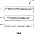
- Fig. 6 is a flowchart of a method 600 of treating an ophthalmic condition.
- the method 600 includes a number of enumerated steps, but embodiments of the method 600 may include additional steps before, after, and in between the enumerated steps.
- the illustrated embodiment begins in step 602 in which a surgeon inserts a probe that includes at least one pressure sensor through a sclera into a vitreous chamber of a patient.
- a vitreous chamber pressure is measured, using the pressure sensor, to provide a vitreous chamber pressure measurement.
- a vitreous humor removal procedure is adjusted according to the vitreous chamber pressure measurement.
- step 602 may be performed when a surgeon inserts the probe system 410 and the infusion line 420. Either or both of these two components, the probe system 410 and the infusion line 420, include at least one pressure sensor for attaining pressure measurements. As illustrated in Fig. 4 , the probe system 410 includes three pressure sensors, while the infusion line 420 includes two. Step 604 may be performed by using either or both of the pressure sensors 428 and 414 in order to obtain a pressure measurement or measurements within the vitreous chamber 404.
- Pressure data obtained from the pressure sensors 428 and/or 414 may be provided to a console 102 configured to process the data.
- the console 102 communicates the pressure data to the surgeon in order to properly adjust a vitreous humor removal rate according to the measured vitreous chamber pressure, in step 606.
- the console 102 may automatically adjust parameters associated with the vitreous humor removal procedure such as a suction pressure and/or a cutter speed.
- the console 102 may automatically adjust the flow of replacement fluid entering the vitreous chamber 404 through the infusion line 420. The flow of a replacement fluid may also be adjusted by the surgeon based on the obtained pressure measurements.
- the various pressure sensors of the probe system 410 and/or the infusion line 420 may be used to measure other pressures including ambient pressures and suction pressures. These additional pressure measurements may be used in calculating a differential pressure, such as intraocular pressure, that may be used as an alternative or in addition to the measured vitreous chamber pressure.
- pressure measured at any or all of the locations of the pressure sensors may provide a surgeon or the console 102 with information to monitor and correct the performance of the procedure while it is underway.
- the systems and methods disclosed herein may be used to provide better performance of vitrectomy probe system and surgical systems by enabling pressure measurements to be obtained that multiple sites of interest during a surgical procedure. This additional information may enable a surgeon to better tailor parameters such as a removal rate and/or a fluid replacement rate in order to maintain pressures within the vitreous chamber 404 at appropriate levels. Similarly, the pressure information may allow for the automatic adjustment of these rates and others by the console 102. This may result in more effective treatment and more accurate data, thereby improving the overall clinical result.
Landscapes
- Health & Medical Sciences (AREA)
- Life Sciences & Earth Sciences (AREA)
- Heart & Thoracic Surgery (AREA)
- General Health & Medical Sciences (AREA)
- Public Health (AREA)
- Engineering & Computer Science (AREA)
- Biomedical Technology (AREA)
- Animal Behavior & Ethology (AREA)
- Veterinary Medicine (AREA)
- Ophthalmology & Optometry (AREA)
- Hematology (AREA)
- Anesthesiology (AREA)
- Surgery (AREA)
- Vascular Medicine (AREA)
- Nuclear Medicine, Radiotherapy & Molecular Imaging (AREA)
- Physics & Mathematics (AREA)
- Molecular Biology (AREA)
- Medical Informatics (AREA)
- Biophysics (AREA)
- Fluid Mechanics (AREA)
- External Artificial Organs (AREA)
- Surgical Instruments (AREA)
- Eye Examination Apparatus (AREA)
- Infusion, Injection, And Reservoir Apparatuses (AREA)
Claims (7)
- Système (100 ; 410) permettant de fournir une irrigation dans un oeil (400) d'un patient pendant un acte médical, le système comprenant :une ligne de perfusion (420) conçue pour placer une source de fluide en communication fluidique avec l'oeil du patient, la ligne de perfusion comprenant :un élément allongé relativement plus flexible (422) possédant une extrémité proximale, une extrémité distale et une lumière s'étendant à travers celui-ci depuis l'extrémité proximale vers l'extrémité distale, la lumière étant conçue pour faire passer le fluide d'irrigation vers l'oeil du patient ;un élément de mise en prise relativement plus rigide (424) au niveau de l'extrémité distale, l'élément de mise en prise étant conçu pour entrer dans une chambre vitrée de l'oeil du patient ; etune pluralité de capteurs de pression (426, 428 ; 502 à 510) connectés à la ligne de perfusion et conçus pour mesurer une ou plusieurs pressions associées à la ligne de perfusion pendant l'acte médical ;caractérisé en ce que
au moins trois des capteurs de pression (502, 504, 506) sont disposés intérieurement en différents emplacements le long de la ligne de perfusion et conçus pour mesurer une ou plusieurs pressions dans la ligne de perfusion pendant l'acte médical, les au moins trois capteurs de pression étant conçus pour détecter un différentiel de pression égal à la différence entre une mesure de capteur de pression donnée et la mesure d'un capteur plus proche, les mesures de différentiel de pression pouvant être utilisées pour indiquer une présence et un emplacement général d'un obstacle (512) au flux le long de la ligne de perfusion entre deux des au moins trois capteurs de pression. - Système selon la revendication 1, comprenant en outre un renfoncement formé dans l'élément allongé flexible (422), l'ouverture du renfoncement donnant sur la lumière et contenant au moins un des au moins trois capteurs de pression.
- Système selon la revendication 2, dans lequel les au moins trois capteurs de pression (502 à 510) sont espacés régulièrement le long d'une partie de la longueur de l'élément allongé flexible (422).
- Système selon la revendication 1, comprenant en outre une console, la console recevant des données de pression en provenance des au moins trois capteurs de pression (502 à 510) et étant conçue pour identifier l'emplacement général de l'obstacle (512) au flux le long de l'élément allongé flexible (422) sur la base des données de pression.
- Système selon la revendication 1, comprenant en outre un élément de couplage par fibre optique ou un élément de couplage électrique disposé au niveau de l'extrémité proximale de l'élément allongé flexible (422).
- Système selon la revendication 1, dans lequel un premier capteur de pression supplémentaire (428) est disposé sur une surface externe de l'élément de mise en prise rigide (424) de façon à mesurer une pression dans une chambre vitrée lorsque l'élément de mise en prise rigide est introduit dans l'oeil.
- Système selon la revendication 6, dans lequel un second capteur de pression supplémentaire (426) est disposé sur une surface externe de l'élément allongé flexible (422) de façon à mesurer une pression ambiante.
Applications Claiming Priority (2)
| Application Number | Priority Date | Filing Date | Title |
|---|---|---|---|
| US14/090,360 US10137034B2 (en) | 2013-11-26 | 2013-11-26 | Pressure-sensing vitrectomy surgical systems and methods |
| PCT/US2014/064423 WO2015080851A1 (fr) | 2013-11-26 | 2014-11-06 | Systèmes et procédés chirurgicaux de vitrectomie à détection de pression |
Publications (3)
| Publication Number | Publication Date |
|---|---|
| EP3048951A1 EP3048951A1 (fr) | 2016-08-03 |
| EP3048951A4 EP3048951A4 (fr) | 2016-12-07 |
| EP3048951B1 true EP3048951B1 (fr) | 2018-12-26 |
Family
ID=53183261
Family Applications (1)
| Application Number | Title | Priority Date | Filing Date |
|---|---|---|---|
| EP14865260.5A Not-in-force EP3048951B1 (fr) | 2013-11-26 | 2014-11-06 | Systèmes chirurgicaux de vitrectomie à détection de pression |
Country Status (12)
| Country | Link |
|---|---|
| US (1) | US10137034B2 (fr) |
| EP (1) | EP3048951B1 (fr) |
| JP (1) | JP6321806B2 (fr) |
| KR (1) | KR101837031B1 (fr) |
| CN (1) | CN105813544B (fr) |
| AU (1) | AU2014355099B2 (fr) |
| BR (1) | BR112016011649A2 (fr) |
| CA (1) | CA2930406A1 (fr) |
| ES (1) | ES2718028T3 (fr) |
| MX (1) | MX2016006874A (fr) |
| RU (1) | RU2651086C2 (fr) |
| WO (1) | WO2015080851A1 (fr) |
Families Citing this family (35)
| Publication number | Priority date | Publication date | Assignee | Title |
|---|---|---|---|---|
| US8968396B2 (en) | 2007-07-23 | 2015-03-03 | Powervision, Inc. | Intraocular lens delivery systems and methods of use |
| US20170360609A9 (en) | 2007-09-24 | 2017-12-21 | Ivantis, Inc. | Methods and devices for increasing aqueous humor outflow |
| WO2011106435A2 (fr) | 2010-02-23 | 2011-09-01 | Powervision, Inc. | Fluide pour recevoir des lentilles intraoculaires |
| US10617558B2 (en) | 2012-11-28 | 2020-04-14 | Ivantis, Inc. | Apparatus for delivering ocular implants into an anterior chamber of the eye |
| US9486358B2 (en) | 2012-12-17 | 2016-11-08 | Abbott Medical Optics Inc. | Vitrectomy surgical apparatus |
| US9498376B2 (en) | 2012-12-17 | 2016-11-22 | Abbott Medical Optics Inc. | Vitrectomy surgical apparatus with cut timing based on pressures encountered |
| EP3785668A1 (fr) | 2013-03-15 | 2021-03-03 | Alcon Inc. | Dispositifs de stockage et de chargement de lentille intra-oculaire et procédés d'utilisation |
| US9757273B2 (en) | 2013-12-20 | 2017-09-12 | Novartis Ag | Tissue-sensing vitrectomy surgical systems and methods |
| CA2946723A1 (fr) * | 2014-04-23 | 2015-10-29 | Abbott Medical Optics Inc. | Appareil chirurgical de vitrectomie utilisant une retroaction de pression a multiples capteurs |
| US10709547B2 (en) | 2014-07-14 | 2020-07-14 | Ivantis, Inc. | Ocular implant delivery system and method |
| EP3215205B1 (fr) * | 2014-11-05 | 2019-10-09 | Palliare Limited | Appareil pour commander le gonflement d'une cavité corporelle au cours d'une procédure chirurgicale ou d'un examen et système de gonflement de cette cavité |
| RU2017130841A (ru) * | 2015-03-03 | 2019-04-03 | Роберто СИТТЕРИО | Хирургическое устройство для глазной хирургии, система и способ компенсации внутриглазного давления |
| ES2962463T3 (es) | 2015-06-10 | 2024-03-19 | Alcon Inc | Materiales y componentes de lentes intraoculares |
| US9707012B2 (en) * | 2015-07-31 | 2017-07-18 | Polygon Medical, Inc. | Polypectomy systems, devices, and methods |
| JP6837475B2 (ja) * | 2015-08-14 | 2021-03-03 | イバンティス インコーポレイテッド | 圧力センサを備えた眼用インプラントおよび送達システム |
| US11938058B2 (en) | 2015-12-15 | 2024-03-26 | Alcon Inc. | Ocular implant and delivery system |
| US9839749B2 (en) * | 2016-04-27 | 2017-12-12 | Novartis Ag | Intraocular pressure sensing systems, devices, and methods |
| US11051978B2 (en) | 2016-05-10 | 2021-07-06 | Alcon Inc. | Automated aspiration throttling in vitreoretinal surgery |
| US11432961B2 (en) | 2016-05-17 | 2022-09-06 | Alcon, Inc. | Automated viscous fluid control in vitreoretinal surgery |
| US10376328B2 (en) * | 2016-08-25 | 2019-08-13 | Novartis Ag | Surgical probe with an integrated motion sensor |
| CN111163717B (zh) | 2017-06-14 | 2023-06-30 | 英姿医疗科技(杭州)有限公司 | 息肉切除术系统、设备和方法 |
| US10639197B2 (en) * | 2017-06-19 | 2020-05-05 | Alcon Inc. | Vitrectomy probe |
| USD847992S1 (en) | 2017-06-27 | 2019-05-07 | Polygon Medical, Inc. | Medical device handle |
| US11324557B2 (en) * | 2017-12-28 | 2022-05-10 | Cilag Gmbh International | Surgical instrument with a sensing array |
| EP4371535A3 (fr) | 2018-02-22 | 2024-08-14 | Alcon Inc. | Implant oculaire et système de pose |
| WO2020031182A1 (fr) | 2018-08-06 | 2020-02-13 | Hadasit Medical Research Services And Development Ltd. | Seringues multi-lumière pour injections intraoculaires |
| CA3147050A1 (fr) | 2019-09-16 | 2021-03-25 | Nathaniel REYES | Sonde de vitrectomie a vibrations reduites |
| US12285217B2 (en) | 2020-05-15 | 2025-04-29 | Icahn School Of Medicine At Mount Sinai | Methods, devices, and systems for monitoring intraocular pressure |
| CN113041018B (zh) * | 2020-11-25 | 2021-12-14 | 冯梅艳 | 眼球玻璃体切割治疗系统 |
| AU2022205382B2 (en) | 2021-01-11 | 2026-02-19 | Alcon Inc. | Systems and methods for viscoelastic delivery |
| EP4329643A4 (fr) | 2021-04-27 | 2025-03-12 | Contego Medical, Inc. | Système d'aspiration de thrombus et procédés de contrôle de la perte de sang |
| US12137960B2 (en) | 2021-05-25 | 2024-11-12 | Arthrex, Inc. | Surgical system with adaptive aspiration flow control |
| US12290274B2 (en) | 2021-05-25 | 2025-05-06 | Arthrex, Inc. | Dynamically controlling a distal window opening in a rotary surgical shaver |
| JP2026513022A (ja) * | 2023-03-22 | 2026-04-22 | アルコン インコーポレイティド | 眼科手術用の圧力センサを統合した外科用器具 |
| CN116616995A (zh) * | 2023-07-21 | 2023-08-22 | 北京衔微医疗科技有限公司 | 一种眼底血管注射设备及控制方法 |
Family Cites Families (28)
| Publication number | Priority date | Publication date | Assignee | Title |
|---|---|---|---|---|
| US4548205A (en) | 1982-10-27 | 1985-10-22 | Armeniades C D | Ophthalmic instrument for measuring intraocular fluid pressure |
| US4722350A (en) * | 1984-09-21 | 1988-02-02 | Armeniades C D | Ophthalmic instrument for measuring intraocular fluid pressure |
| US4841984A (en) | 1985-09-16 | 1989-06-27 | Armoor Ophthalmics, Inc. | Fluid-carrying components of apparatus for automatic control of intraocular pressure |
| JPH0349756A (ja) | 1989-07-19 | 1991-03-04 | Topcon Corp | 灌流用ボトル高さ表示装置 |
| EP0482858A3 (en) | 1990-10-26 | 1992-07-08 | Alcon Surgical, Inc., | Surgical infusion control system |
| US5989262A (en) * | 1996-04-15 | 1999-11-23 | Josephberg; Robert Gary | Sutureless pars plana vitrectomy tool |
| US5865764A (en) | 1996-12-30 | 1999-02-02 | Armoor Opthalmics, Inc. | Device and method for noninvasive measurement of internal pressure within body cavities |
| US20010016707A1 (en) | 1998-07-13 | 2001-08-23 | Alex Urich | Venting apparatus for eye surgery |
| US6179808B1 (en) | 1999-06-18 | 2001-01-30 | Alcon Laboratories, Inc. | Method of controlling the operating parameters of a surgical system |
| US6962488B2 (en) | 1999-11-10 | 2005-11-08 | Alcon, Inc. | Surgical cassette having an aspiration pressure sensor |
| US6743245B2 (en) | 1999-12-20 | 2004-06-01 | Alcon Universal Ltd. | Asynchronous method of operating microsurgical instruments |
| JP2004507321A (ja) | 2000-08-29 | 2004-03-11 | アルコン マニュファクチャリング,リミティド | 注入制御システム |
| WO2002026016A2 (fr) | 2000-09-25 | 2002-04-04 | Alcon Universal Ltd. | Procede relatif au fonctionnement d'un systeme de controle d'injection |
| US7524299B2 (en) | 2005-06-21 | 2009-04-28 | Alcon, Inc. | Aspiration control |
| US7644603B2 (en) | 2005-06-27 | 2010-01-12 | Alcon, Inc. | Method of testing a surgical system |
| US7648465B2 (en) | 2005-06-28 | 2010-01-19 | Alcon, Inc. | Method of testing a surgical system |
| US8465467B2 (en) | 2006-09-14 | 2013-06-18 | Novartis Ag | Method of controlling an irrigation/aspiration system |
| US8876751B2 (en) * | 2009-08-06 | 2014-11-04 | Alcon Research, Ltd. | Phacoemulsification handpiece pressure booster |
| US20110137231A1 (en) | 2009-12-08 | 2011-06-09 | Alcon Research, Ltd. | Phacoemulsification Hand Piece With Integrated Aspiration Pump |
| US8287486B2 (en) * | 2010-05-25 | 2012-10-16 | Alcon Research, Ltd. | Infusion pressure monitoring system |
| RU2434608C1 (ru) * | 2010-06-02 | 2011-11-27 | Закрытое акционерное общество "Оптимедсервис" | Аспирационный насос для офтальмохирургических систем |
| US8888802B2 (en) | 2010-12-21 | 2014-11-18 | Alcon Research, Ltd. | Vitrectomy probe with adjustable cutter port size |
| PL2766064T3 (pl) | 2011-12-08 | 2017-08-31 | Alcon Research, Ltd. | Selektywnie przemieszczalne elementy zaworowe dla obwodów zasysania i irygacji |
| US9119699B2 (en) | 2012-10-22 | 2015-09-01 | Alcon Research, Ltd. | Pressure control in phacoemulsification system |
| US9119701B2 (en) | 2012-10-22 | 2015-09-01 | Alcon Research, Ltd. | Pressure control in phacoemulsification system |
| WO2014092851A1 (fr) | 2012-12-11 | 2014-06-19 | Alcon Research, Ltd. | Pièce à main de phacoémulsification avec pompe d'aspiration et d'irrigation intégrée |
| US9549850B2 (en) | 2013-04-26 | 2017-01-24 | Novartis Ag | Partial venting system for occlusion surge mitigation |
| US9757273B2 (en) | 2013-12-20 | 2017-09-12 | Novartis Ag | Tissue-sensing vitrectomy surgical systems and methods |
-
2013
- 2013-11-26 US US14/090,360 patent/US10137034B2/en active Active
-
2014
- 2014-11-06 CN CN201480064241.0A patent/CN105813544B/zh not_active Expired - Fee Related
- 2014-11-06 KR KR1020167013855A patent/KR101837031B1/ko not_active Expired - Fee Related
- 2014-11-06 ES ES14865260T patent/ES2718028T3/es active Active
- 2014-11-06 WO PCT/US2014/064423 patent/WO2015080851A1/fr not_active Ceased
- 2014-11-06 CA CA2930406A patent/CA2930406A1/fr not_active Abandoned
- 2014-11-06 JP JP2016534215A patent/JP6321806B2/ja active Active
- 2014-11-06 RU RU2016118747A patent/RU2651086C2/ru not_active IP Right Cessation
- 2014-11-06 BR BR112016011649A patent/BR112016011649A2/pt not_active Application Discontinuation
- 2014-11-06 EP EP14865260.5A patent/EP3048951B1/fr not_active Not-in-force
- 2014-11-06 MX MX2016006874A patent/MX2016006874A/es unknown
- 2014-11-06 AU AU2014355099A patent/AU2014355099B2/en not_active Ceased
Non-Patent Citations (1)
| Title |
|---|
| None * |
Also Published As
| Publication number | Publication date |
|---|---|
| MX2016006874A (es) | 2016-11-25 |
| JP6321806B2 (ja) | 2018-05-09 |
| AU2014355099B2 (en) | 2017-03-30 |
| RU2651086C2 (ru) | 2018-04-18 |
| JP2016538070A (ja) | 2016-12-08 |
| BR112016011649A2 (pt) | 2017-08-08 |
| ES2718028T3 (es) | 2019-06-27 |
| US20150148836A1 (en) | 2015-05-28 |
| KR101837031B1 (ko) | 2018-03-09 |
| KR20160075720A (ko) | 2016-06-29 |
| AU2014355099A1 (en) | 2016-06-09 |
| CN105813544A (zh) | 2016-07-27 |
| EP3048951A4 (fr) | 2016-12-07 |
| CN105813544B (zh) | 2018-04-10 |
| CA2930406A1 (fr) | 2015-06-04 |
| EP3048951A1 (fr) | 2016-08-03 |
| US10137034B2 (en) | 2018-11-27 |
| WO2015080851A1 (fr) | 2015-06-04 |
| RU2016118747A (ru) | 2018-01-09 |
Similar Documents
| Publication | Publication Date | Title |
|---|---|---|
| US10137034B2 (en) | Pressure-sensing vitrectomy surgical systems and methods | |
| EP1895958B1 (fr) | Procede de test d'un systeme chirurgical | |
| EP0110560B1 (fr) | Appareil ophtalmique pour mesurer la pression du fluide intraoculaire | |
| US10702415B2 (en) | Surgical apparatus including aspiration device sensors | |
| US11051978B2 (en) | Automated aspiration throttling in vitreoretinal surgery | |
| EP3082670B1 (fr) | Système chirurgique de vitrectomie avec détection de tissu | |
| EP3362113B1 (fr) | Mesure de la pression optique pour chirurgie fluidique ophtalmique | |
| EP4037628B1 (fr) | Systèmes d'identification de type de cassette dans un système chirurgical | |
| US20240315872A1 (en) | Surgical instrument with integrated pressure sensor for ophthalmic surgeries | |
| EP4039184A1 (fr) | Dispositif de détection directe des variations de pression d'un fluide dans une cavité corporelle |
Legal Events
| Date | Code | Title | Description |
|---|---|---|---|
| PUAI | Public reference made under article 153(3) epc to a published international application that has entered the european phase |
Free format text: ORIGINAL CODE: 0009012 |
|
| 17P | Request for examination filed |
Effective date: 20160429 |
|
| AK | Designated contracting states |
Kind code of ref document: A1 Designated state(s): AL AT BE BG CH CY CZ DE DK EE ES FI FR GB GR HR HU IE IS IT LI LT LU LV MC MK MT NL NO PL PT RO RS SE SI SK SM TR |
|
| AX | Request for extension of the european patent |
Extension state: BA ME |
|
| A4 | Supplementary search report drawn up and despatched |
Effective date: 20161108 |
|
| RIC1 | Information provided on ipc code assigned before grant |
Ipc: A61B 3/16 20060101AFI20161102BHEP Ipc: A61F 9/007 20060101ALI20161102BHEP |
|
| DAX | Request for extension of the european patent (deleted) | ||
| GRAP | Despatch of communication of intention to grant a patent |
Free format text: ORIGINAL CODE: EPIDOSNIGR1 |
|
| STAA | Information on the status of an ep patent application or granted ep patent |
Free format text: STATUS: GRANT OF PATENT IS INTENDED |
|
| INTG | Intention to grant announced |
Effective date: 20180608 |
|
| RIN1 | Information on inventor provided before grant (corrected) |
Inventor name: HEEREN, TAMMO |
|
| GRAS | Grant fee paid |
Free format text: ORIGINAL CODE: EPIDOSNIGR3 |
|
| GRAJ | Information related to disapproval of communication of intention to grant by the applicant or resumption of examination proceedings by the epo deleted |
Free format text: ORIGINAL CODE: EPIDOSDIGR1 |
|
| GRAL | Information related to payment of fee for publishing/printing deleted |
Free format text: ORIGINAL CODE: EPIDOSDIGR3 |
|
| STAA | Information on the status of an ep patent application or granted ep patent |
Free format text: STATUS: REQUEST FOR EXAMINATION WAS MADE |
|
| GRAR | Information related to intention to grant a patent recorded |
Free format text: ORIGINAL CODE: EPIDOSNIGR71 |
|
| STAA | Information on the status of an ep patent application or granted ep patent |
Free format text: STATUS: GRANT OF PATENT IS INTENDED |
|
| INTC | Intention to grant announced (deleted) | ||
| INTG | Intention to grant announced |
Effective date: 20180927 |
|
| GRAA | (expected) grant |
Free format text: ORIGINAL CODE: 0009210 |
|
| STAA | Information on the status of an ep patent application or granted ep patent |
Free format text: STATUS: THE PATENT HAS BEEN GRANTED |
|
| AK | Designated contracting states |
Kind code of ref document: B1 Designated state(s): AL AT BE BG CH CY CZ DE DK EE ES FI FR GB GR HR HU IE IS IT LI LT LU LV MC MK MT NL NO PL PT RO RS SE SI SK SM TR |
|
| REG | Reference to a national code |
Ref country code: GB Ref legal event code: FG4D |
|
| REG | Reference to a national code |
Ref country code: CH Ref legal event code: EP |
|
| REG | Reference to a national code |
Ref country code: AT Ref legal event code: REF Ref document number: 1080282 Country of ref document: AT Kind code of ref document: T Effective date: 20190115 |
|
| REG | Reference to a national code |
Ref country code: IE Ref legal event code: FG4D |
|
| REG | Reference to a national code |
Ref country code: DE Ref legal event code: R096 Ref document number: 602014038879 Country of ref document: DE |
|
| PG25 | Lapsed in a contracting state [announced via postgrant information from national office to epo] |
Ref country code: NO Free format text: LAPSE BECAUSE OF FAILURE TO SUBMIT A TRANSLATION OF THE DESCRIPTION OR TO PAY THE FEE WITHIN THE PRESCRIBED TIME-LIMIT Effective date: 20190326 Ref country code: HR Free format text: LAPSE BECAUSE OF FAILURE TO SUBMIT A TRANSLATION OF THE DESCRIPTION OR TO PAY THE FEE WITHIN THE PRESCRIBED TIME-LIMIT Effective date: 20181226 Ref country code: LT Free format text: LAPSE BECAUSE OF FAILURE TO SUBMIT A TRANSLATION OF THE DESCRIPTION OR TO PAY THE FEE WITHIN THE PRESCRIBED TIME-LIMIT Effective date: 20181226 Ref country code: BG Free format text: LAPSE BECAUSE OF FAILURE TO SUBMIT A TRANSLATION OF THE DESCRIPTION OR TO PAY THE FEE WITHIN THE PRESCRIBED TIME-LIMIT Effective date: 20190326 Ref country code: FI Free format text: LAPSE BECAUSE OF FAILURE TO SUBMIT A TRANSLATION OF THE DESCRIPTION OR TO PAY THE FEE WITHIN THE PRESCRIBED TIME-LIMIT Effective date: 20181226 Ref country code: LV Free format text: LAPSE BECAUSE OF FAILURE TO SUBMIT A TRANSLATION OF THE DESCRIPTION OR TO PAY THE FEE WITHIN THE PRESCRIBED TIME-LIMIT Effective date: 20181226 |
|
| REG | Reference to a national code |
Ref country code: NL Ref legal event code: MP Effective date: 20181226 |
|
| REG | Reference to a national code |
Ref country code: LT Ref legal event code: MG4D |
|
| PG25 | Lapsed in a contracting state [announced via postgrant information from national office to epo] |
Ref country code: AL Free format text: LAPSE BECAUSE OF FAILURE TO SUBMIT A TRANSLATION OF THE DESCRIPTION OR TO PAY THE FEE WITHIN THE PRESCRIBED TIME-LIMIT Effective date: 20181226 Ref country code: SE Free format text: LAPSE BECAUSE OF FAILURE TO SUBMIT A TRANSLATION OF THE DESCRIPTION OR TO PAY THE FEE WITHIN THE PRESCRIBED TIME-LIMIT Effective date: 20181226 Ref country code: RS Free format text: LAPSE BECAUSE OF FAILURE TO SUBMIT A TRANSLATION OF THE DESCRIPTION OR TO PAY THE FEE WITHIN THE PRESCRIBED TIME-LIMIT Effective date: 20181226 Ref country code: GR Free format text: LAPSE BECAUSE OF FAILURE TO SUBMIT A TRANSLATION OF THE DESCRIPTION OR TO PAY THE FEE WITHIN THE PRESCRIBED TIME-LIMIT Effective date: 20190327 |
|
| REG | Reference to a national code |
Ref country code: AT Ref legal event code: MK05 Ref document number: 1080282 Country of ref document: AT Kind code of ref document: T Effective date: 20181226 |
|
| REG | Reference to a national code |
Ref country code: ES Ref legal event code: FG2A Ref document number: 2718028 Country of ref document: ES Kind code of ref document: T3 Effective date: 20190627 |
|
| PG25 | Lapsed in a contracting state [announced via postgrant information from national office to epo] |
Ref country code: NL Free format text: LAPSE BECAUSE OF FAILURE TO SUBMIT A TRANSLATION OF THE DESCRIPTION OR TO PAY THE FEE WITHIN THE PRESCRIBED TIME-LIMIT Effective date: 20181226 |
|
| PG25 | Lapsed in a contracting state [announced via postgrant information from national office to epo] |
Ref country code: CZ Free format text: LAPSE BECAUSE OF FAILURE TO SUBMIT A TRANSLATION OF THE DESCRIPTION OR TO PAY THE FEE WITHIN THE PRESCRIBED TIME-LIMIT Effective date: 20181226 Ref country code: PL Free format text: LAPSE BECAUSE OF FAILURE TO SUBMIT A TRANSLATION OF THE DESCRIPTION OR TO PAY THE FEE WITHIN THE PRESCRIBED TIME-LIMIT Effective date: 20181226 Ref country code: PT Free format text: LAPSE BECAUSE OF FAILURE TO SUBMIT A TRANSLATION OF THE DESCRIPTION OR TO PAY THE FEE WITHIN THE PRESCRIBED TIME-LIMIT Effective date: 20190426 |
|
| PG25 | Lapsed in a contracting state [announced via postgrant information from national office to epo] |
Ref country code: EE Free format text: LAPSE BECAUSE OF FAILURE TO SUBMIT A TRANSLATION OF THE DESCRIPTION OR TO PAY THE FEE WITHIN THE PRESCRIBED TIME-LIMIT Effective date: 20181226 Ref country code: SM Free format text: LAPSE BECAUSE OF FAILURE TO SUBMIT A TRANSLATION OF THE DESCRIPTION OR TO PAY THE FEE WITHIN THE PRESCRIBED TIME-LIMIT Effective date: 20181226 Ref country code: IS Free format text: LAPSE BECAUSE OF FAILURE TO SUBMIT A TRANSLATION OF THE DESCRIPTION OR TO PAY THE FEE WITHIN THE PRESCRIBED TIME-LIMIT Effective date: 20190426 Ref country code: RO Free format text: LAPSE BECAUSE OF FAILURE TO SUBMIT A TRANSLATION OF THE DESCRIPTION OR TO PAY THE FEE WITHIN THE PRESCRIBED TIME-LIMIT Effective date: 20181226 Ref country code: SK Free format text: LAPSE BECAUSE OF FAILURE TO SUBMIT A TRANSLATION OF THE DESCRIPTION OR TO PAY THE FEE WITHIN THE PRESCRIBED TIME-LIMIT Effective date: 20181226 |
|
| REG | Reference to a national code |
Ref country code: DE Ref legal event code: R097 Ref document number: 602014038879 Country of ref document: DE |
|
| PG25 | Lapsed in a contracting state [announced via postgrant information from national office to epo] |
Ref country code: AT Free format text: LAPSE BECAUSE OF FAILURE TO SUBMIT A TRANSLATION OF THE DESCRIPTION OR TO PAY THE FEE WITHIN THE PRESCRIBED TIME-LIMIT Effective date: 20181226 Ref country code: DK Free format text: LAPSE BECAUSE OF FAILURE TO SUBMIT A TRANSLATION OF THE DESCRIPTION OR TO PAY THE FEE WITHIN THE PRESCRIBED TIME-LIMIT Effective date: 20181226 |
|
| PLBE | No opposition filed within time limit |
Free format text: ORIGINAL CODE: 0009261 |
|
| STAA | Information on the status of an ep patent application or granted ep patent |
Free format text: STATUS: NO OPPOSITION FILED WITHIN TIME LIMIT |
|
| 26N | No opposition filed |
Effective date: 20190927 |
|
| PGFP | Annual fee paid to national office [announced via postgrant information from national office to epo] |
Ref country code: DE Payment date: 20191022 Year of fee payment: 6 |
|
| REG | Reference to a national code |
Ref country code: DE Ref legal event code: R081 Ref document number: 602014038879 Country of ref document: DE Owner name: ALCON INC., CH Free format text: FORMER OWNER: NOVARTIS AG, BASEL, CH |
|
| REG | Reference to a national code |
Ref country code: GB Ref legal event code: 732E Free format text: REGISTERED BETWEEN 20200123 AND 20200129 |
|
| PG25 | Lapsed in a contracting state [announced via postgrant information from national office to epo] |
Ref country code: SI Free format text: LAPSE BECAUSE OF FAILURE TO SUBMIT A TRANSLATION OF THE DESCRIPTION OR TO PAY THE FEE WITHIN THE PRESCRIBED TIME-LIMIT Effective date: 20181226 |
|
| PGFP | Annual fee paid to national office [announced via postgrant information from national office to epo] |
Ref country code: IT Payment date: 20191108 Year of fee payment: 6 Ref country code: FR Payment date: 20191029 Year of fee payment: 6 Ref country code: ES Payment date: 20191202 Year of fee payment: 6 |
|
| PG25 | Lapsed in a contracting state [announced via postgrant information from national office to epo] |
Ref country code: TR Free format text: LAPSE BECAUSE OF FAILURE TO SUBMIT A TRANSLATION OF THE DESCRIPTION OR TO PAY THE FEE WITHIN THE PRESCRIBED TIME-LIMIT Effective date: 20181226 |
|
| REG | Reference to a national code |
Ref country code: ES Ref legal event code: PC2A Owner name: ALCON INC. Effective date: 20200416 |
|
| PGFP | Annual fee paid to national office [announced via postgrant information from national office to epo] |
Ref country code: GB Payment date: 20191108 Year of fee payment: 6 |
|
| REG | Reference to a national code |
Ref country code: CH Ref legal event code: PL |
|
| PG25 | Lapsed in a contracting state [announced via postgrant information from national office to epo] |
Ref country code: CH Free format text: LAPSE BECAUSE OF NON-PAYMENT OF DUE FEES Effective date: 20191130 Ref country code: LU Free format text: LAPSE BECAUSE OF NON-PAYMENT OF DUE FEES Effective date: 20191106 Ref country code: LI Free format text: LAPSE BECAUSE OF NON-PAYMENT OF DUE FEES Effective date: 20191130 Ref country code: MC Free format text: LAPSE BECAUSE OF FAILURE TO SUBMIT A TRANSLATION OF THE DESCRIPTION OR TO PAY THE FEE WITHIN THE PRESCRIBED TIME-LIMIT Effective date: 20181226 |
|
| REG | Reference to a national code |
Ref country code: BE Ref legal event code: MM Effective date: 20191130 |
|
| PG25 | Lapsed in a contracting state [announced via postgrant information from national office to epo] |
Ref country code: IE Free format text: LAPSE BECAUSE OF NON-PAYMENT OF DUE FEES Effective date: 20191106 |
|
| PG25 | Lapsed in a contracting state [announced via postgrant information from national office to epo] |
Ref country code: BE Free format text: LAPSE BECAUSE OF NON-PAYMENT OF DUE FEES Effective date: 20191130 |
|
| PG25 | Lapsed in a contracting state [announced via postgrant information from national office to epo] |
Ref country code: CY Free format text: LAPSE BECAUSE OF FAILURE TO SUBMIT A TRANSLATION OF THE DESCRIPTION OR TO PAY THE FEE WITHIN THE PRESCRIBED TIME-LIMIT Effective date: 20181226 |
|
| REG | Reference to a national code |
Ref country code: DE Ref legal event code: R119 Ref document number: 602014038879 Country of ref document: DE |
|
| GBPC | Gb: european patent ceased through non-payment of renewal fee |
Effective date: 20201106 |
|
| PG25 | Lapsed in a contracting state [announced via postgrant information from national office to epo] |
Ref country code: MT Free format text: LAPSE BECAUSE OF FAILURE TO SUBMIT A TRANSLATION OF THE DESCRIPTION OR TO PAY THE FEE WITHIN THE PRESCRIBED TIME-LIMIT Effective date: 20181226 Ref country code: HU Free format text: LAPSE BECAUSE OF FAILURE TO SUBMIT A TRANSLATION OF THE DESCRIPTION OR TO PAY THE FEE WITHIN THE PRESCRIBED TIME-LIMIT; INVALID AB INITIO Effective date: 20141106 |
|
| PG25 | Lapsed in a contracting state [announced via postgrant information from national office to epo] |
Ref country code: FR Free format text: LAPSE BECAUSE OF NON-PAYMENT OF DUE FEES Effective date: 20201130 Ref country code: IT Free format text: LAPSE BECAUSE OF NON-PAYMENT OF DUE FEES Effective date: 20201106 |
|
| PG25 | Lapsed in a contracting state [announced via postgrant information from national office to epo] |
Ref country code: GB Free format text: LAPSE BECAUSE OF NON-PAYMENT OF DUE FEES Effective date: 20201106 Ref country code: DE Free format text: LAPSE BECAUSE OF NON-PAYMENT OF DUE FEES Effective date: 20210601 |
|
| REG | Reference to a national code |
Ref country code: ES Ref legal event code: FD2A Effective date: 20220131 |
|
| PG25 | Lapsed in a contracting state [announced via postgrant information from national office to epo] |
Ref country code: ES Free format text: LAPSE BECAUSE OF NON-PAYMENT OF DUE FEES Effective date: 20201107 |
|
| PG25 | Lapsed in a contracting state [announced via postgrant information from national office to epo] |
Ref country code: MK Free format text: LAPSE BECAUSE OF FAILURE TO SUBMIT A TRANSLATION OF THE DESCRIPTION OR TO PAY THE FEE WITHIN THE PRESCRIBED TIME-LIMIT Effective date: 20181226 |