EP3049189B1 - Buse et pistolet de pulvérisation à froid simplifiés - Google Patents
Buse et pistolet de pulvérisation à froid simplifiés Download PDFInfo
- Publication number
- EP3049189B1 EP3049189B1 EP14846824.2A EP14846824A EP3049189B1 EP 3049189 B1 EP3049189 B1 EP 3049189B1 EP 14846824 A EP14846824 A EP 14846824A EP 3049189 B1 EP3049189 B1 EP 3049189B1
- Authority
- EP
- European Patent Office
- Prior art keywords
- nozzle
- powder
- conduit
- fitting
- compression
- Prior art date
- Legal status (The legal status is an assumption and is not a legal conclusion. Google has not performed a legal analysis and makes no representation as to the accuracy of the status listed.)
- Active
Links
Images



Classifications
-
- B—PERFORMING OPERATIONS; TRANSPORTING
- B05—SPRAYING OR ATOMISING IN GENERAL; APPLYING FLUENT MATERIALS TO SURFACES, IN GENERAL
- B05B—SPRAYING APPARATUS; ATOMISING APPARATUS; NOZZLES
- B05B7/00—Spraying apparatus for discharge of liquids or other fluent materials from two or more sources, e.g. of liquid and air, of powder and gas
- B05B7/16—Spraying apparatus for discharge of liquids or other fluent materials from two or more sources, e.g. of liquid and air, of powder and gas incorporating means for heating or cooling the material to be sprayed
- B05B7/1606—Spraying apparatus for discharge of liquids or other fluent materials from two or more sources, e.g. of liquid and air, of powder and gas incorporating means for heating or cooling the material to be sprayed the spraying of the material involving the use of an atomising fluid, e.g. air
- B05B7/1613—Spraying apparatus for discharge of liquids or other fluent materials from two or more sources, e.g. of liquid and air, of powder and gas incorporating means for heating or cooling the material to be sprayed the spraying of the material involving the use of an atomising fluid, e.g. air comprising means for heating the atomising fluid before mixing with the material to be sprayed
- B05B7/162—Spraying apparatus for discharge of liquids or other fluent materials from two or more sources, e.g. of liquid and air, of powder and gas incorporating means for heating or cooling the material to be sprayed the spraying of the material involving the use of an atomising fluid, e.g. air comprising means for heating the atomising fluid before mixing with the material to be sprayed and heat being transferred from the atomising fluid to the material to be sprayed
- B05B7/1626—Spraying apparatus for discharge of liquids or other fluent materials from two or more sources, e.g. of liquid and air, of powder and gas incorporating means for heating or cooling the material to be sprayed the spraying of the material involving the use of an atomising fluid, e.g. air comprising means for heating the atomising fluid before mixing with the material to be sprayed and heat being transferred from the atomising fluid to the material to be sprayed at the moment of mixing
-
- B—PERFORMING OPERATIONS; TRANSPORTING
- B05—SPRAYING OR ATOMISING IN GENERAL; APPLYING FLUENT MATERIALS TO SURFACES, IN GENERAL
- B05B—SPRAYING APPARATUS; ATOMISING APPARATUS; NOZZLES
- B05B15/00—Details of spraying plant or spraying apparatus not otherwise provided for; Accessories
- B05B15/60—Arrangements for mounting, supporting or holding spraying apparatus
- B05B15/65—Mounting arrangements for fluid connection of the spraying apparatus or its outlets to flow conduits
-
- B—PERFORMING OPERATIONS; TRANSPORTING
- B05—SPRAYING OR ATOMISING IN GENERAL; APPLYING FLUENT MATERIALS TO SURFACES, IN GENERAL
- B05B—SPRAYING APPARATUS; ATOMISING APPARATUS; NOZZLES
- B05B7/00—Spraying apparatus for discharge of liquids or other fluent materials from two or more sources, e.g. of liquid and air, of powder and gas
- B05B7/02—Spray pistols; Apparatus for discharge
-
- B—PERFORMING OPERATIONS; TRANSPORTING
- B05—SPRAYING OR ATOMISING IN GENERAL; APPLYING FLUENT MATERIALS TO SURFACES, IN GENERAL
- B05B—SPRAYING APPARATUS; ATOMISING APPARATUS; NOZZLES
- B05B7/00—Spraying apparatus for discharge of liquids or other fluent materials from two or more sources, e.g. of liquid and air, of powder and gas
- B05B7/14—Spraying apparatus for discharge of liquids or other fluent materials from two or more sources, e.g. of liquid and air, of powder and gas designed for spraying particulate materials
- B05B7/1481—Spray pistols or apparatus for discharging particulate material
- B05B7/1486—Spray pistols or apparatus for discharging particulate material for spraying particulate material in dry state
-
- C—CHEMISTRY; METALLURGY
- C23—COATING METALLIC MATERIAL; COATING MATERIAL WITH METALLIC MATERIAL; CHEMICAL SURFACE TREATMENT; DIFFUSION TREATMENT OF METALLIC MATERIAL; COATING BY VACUUM EVAPORATION, BY SPUTTERING, BY ION IMPLANTATION OR BY CHEMICAL VAPOUR DEPOSITION, IN GENERAL; INHIBITING CORROSION OF METALLIC MATERIAL OR INCRUSTATION IN GENERAL
- C23C—COATING METALLIC MATERIAL; COATING MATERIAL WITH METALLIC MATERIAL; SURFACE TREATMENT OF METALLIC MATERIAL BY DIFFUSION INTO THE SURFACE, BY CHEMICAL CONVERSION OR SUBSTITUTION; COATING BY VACUUM EVAPORATION, BY SPUTTERING, BY ION IMPLANTATION OR BY CHEMICAL VAPOUR DEPOSITION, IN GENERAL
- C23C24/00—Coating starting from inorganic powder
- C23C24/02—Coating starting from inorganic powder by application of pressure only
- C23C24/04—Impact or kinetic deposition of particles
Definitions
- the disclosure relates to a cold spray nozzle assembly used in a cold spray system that deposits a powder material onto a substrate.
- Cold spray systems range in capability from high temperature, high pressure systems to lower pressure and temperature systems. In all cases it is crucial to have a nozzle with the correct geometry capable of withstanding the temperatures and pressures used in the device. These nozzles are designed to fit the equipment using special flanges, tapered sleeves, or the like. Further, the guns to which the nozzles are affixed are typically designed as pressure vessels generally for the purpose of mixing and porting the gases and powders to the nozzle.
- US 2005/0242582 A1 discloses a prior art cold spray nozzle assembly as set forth in the preamble of claim 1.
- the present disclosure provides a cold spray nozzle and gun which simplifies the connection of the nozzle to the gun, and helps to provide a much more compact nozzle assembly, thereby allowing a cold spray gun to be used to apply powdered materials to substrates in locations which would be difficult if not impossible to reach using conventional devices.
- a cold spray nozzle assembly is provided as set forth in claim 1.
- the nozzle can be provided with a notch on an outer diameter which is aligned with the compression ring whereby the compression ring engages the notch when the compression nut is tightened relative to the receiving fitting.
- the receiving fitting can be threaded to the conduit.
- the nozzle can have an inlet and an outlet end and a throat section, and an inlet for feeding the powder to the nozzle can be provided in the form of a tube or other conduit for carrying the powder, wherein the tube extends along an axis of the nozzle from the inlet end and through the throat section of the nozzle.
- the inlet end of the nozzle can be provided with rounded edges.
- This aspect of the invention can be combined with compression tube fittings as discussed above, for example connecting the nozzle to the conduit.
- the present disclosure provides a much more compact assembly as compared to known devices, and does so by connecting the nozzle to a flow conduit of the cold spray nozzle device using a compression tube fitting, which allows for a tight seal with the nozzle through commonly available temperature and pressure rated fittings and ferrules. Construction of the gun can then be accomplished using standard tubing and fittings capable of withstanding the required temperatures and pressures.
- FIGS. 2-4 illustrate cold spray guns or systems incorporating the cold spray nozzle assembly in accordance with the present disclosure.
- a cold spray system 10 is shown having a nozzle 12, a conduit 14 for carrying hot gas, and a feed 16 for powder.
- FIG. 4 also shows a connection 18 for a thermocouple to monitor temperature within nozzle 12 as desired.
- ports 16 and 18 can additionally be reversed such that 18 is for powder and 16 is used for a thermocouple.
- hot gas is fed through conduit 14 to nozzle 12, and powder is fed through the flow of hot gas in conduit 14 such that the hot gas and powder are propelled through the nozzle 12 for application to a substrate as desired.
- powder can be heated by being carried along a conduit along with a hot gas, and the extent to which the powder is heated can be controlled by adjusting where with respect to the flow of hot gas and nozzle the powder is injected. The longer the powder is carried by the hot gas prior to being sprayed through the nozzle, the more heat is transferred to the powder, which can be desired or undesirable, depending upon the application and the powder being used.
- FIGS. 2 and 3 show similar configurations of systems 10' 10" with nozzle 12, hot gas conduit 14 and powder feed 16 connected in different positions as compared to FIG. 4 .
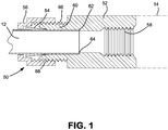
- a cross-sectional view of a compression tube fitting 50 is provided, and shows an end of nozzle 12 held in a receiving fitting 52 and secured there by a compression ring or ferrule 54 which is acted upon by a compression nut 56 to securely hold nozzle 12 in place with respect to receiving fitting 52 as desired.
- Receiving fitting 52 in this embodiment has internal threads 58 which can be used to secure fitting 52 to a conduit such as hot gas conduit 14.
- Receiving fitting 52 can be provided having various other structures for connection to conduits as desired, including external threading and the like.
- receiving fitting 52 has a neck portion 60 extending away from threads 58 for receiving nozzle 12.
- Neck portion 60 has an inside diameter sized to closely fit the outside diameter of nozzle 12, and is also provided with a step 62 on the inside diameter as shown in FIG. 1 .
- Step 62 engages the edge 64 of nozzle 12 and thereby holds nozzle 12 in the proper axial position with respect to receiving fitting 52.
- Neck portion 60 also has outer threads 66 which are used to engage with compression nut 56 so that compression nut 56 can be tightened with respect to receiving fitting 52.
- Compression ring 54 is shown positioned for axial compression between compression nut 56 and receiving fitting 52, and such compression causes compression ring 54 to mechanically secure nozzle 12 relative to receiving fitting 52 (and conduit 14 to which fitting 52 would be connected), and also to seal nozzle 12 in this position.
- Compression nut 56 has internal threads 68 to interact with outer threads 66 of neck portion 60. It should be appreciated that the orientation of threads as shown in the embodiment of FIG. 1 could be reversed under various different circumstances to produce the same structural connection, well within the broad scope of the present disclosure.
- Simplifying the structure in accordance with the present disclosure greatly reduces the stress on the nozzle and also orients most forces in the assembly to be compressive.
- the outside diameter complexity of the nozzle is also greatly reduced, allowing for reduced cost nozzles made from lower strength materials.
- other attachment techniques require threading of the nozzle material, flanges machined into the nozzle with special high temperature seals, or gas type tapers and special tapered flanges, all of which add significantly to the cost of the device.
- Brittle ceramic or cemented carbides, for instance are difficult to machine threads or flanges where localized tensile stresses then limit the structural performance. This forces the use of larger sections of material to reduce the stress sufficiently. These materials can also be costly and difficult to machine thus raising the production costs.
- a simplified straight diameter of common tube size either which can be notched or stepped as described below provides a reduced size material with reduced machining requirements and minimal stress concentrations.
- the primary complexity of a typical cold spray gun is the nozzle assembly.
- the present disclosure allows for the gun to be assembled primarily from off-the-shelf compression fittings and tubings, greatly reducing costs and complexity. Further, by maintaining a ratio of tube area versus nozzle throat area preferably not less than 16:1, proper mixing of powder with hot gas is possible without the need for a special mixing chamber, while the velocity remains sufficiently low that the powder material is not deposited on turns of the tubing leading up to the nozzle. This allows for the complex mixing chambers of known guns to be completely avoided, and further allows for numerous different points of powder injection to provide for increased or decreased powder heating as may be desired.
- FIGS. 2-4 show different arrangements of powder injection to accomplish these different levels of heating.
- conduit 16 for feeding powder is axially aligned with nozzle 12 so that powder is introduced into the flow of hot gas substantially at, or through, the nozzle.
- the powder injection can be positioned to inject powder before or after the throat of the nozzle, as will be discussed further below.
- FIG. 3 shows a configuration in accordance with the present disclosure where powder injection conduit 16 is positioned a short distance upstream from nozzle 12 to allow a portion of flow of powder some further heating in the flow of hot gas before the combination reaches nozzle 12.
- FIG. 3 also shows an advantageous configuration of the present disclosure as the configuration has a relatively small dimension considered laterally with respect to axial extent (axis A) of hot gas conduit 14.
- a cold spray nozzle assembly and cold spray gun having the assembly as illustrated in FIG. 3 could be utilized to deposit a particulate or powdered coating on relatively small inside diameters.
- conduit 14 is positioned between powder inlet 16 and nozzle 12, and this allows for a greater amount of pre-heating before the powder is deposited.
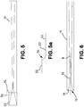
- FIG. 5 is a schematic illustration of a nozzle 12 in accordance with the present disclosure having a step 70 which can be utilized to locate nozzle 12 in the compression tube fitting in accordance with the present disclosure.
- FIG. 5a shows an enlarged portion of FIG. 5 to further illustrate one aspect of the configuration of step 70.
- nozzle 12 can have one outside diameter for the normal extent of nozzle 12, and this outside diameter would be in the portion indicated in the drawings at 20.
- Step 70 leads to a larger outside diameter portion 22.
- the transition from section 22 is illustrated in accordance with one aspect of the disclosure, wherein a gradual curve is provided from the smaller outside diameter section 20 to the larger outside diameter section 22. This can help distribute forces in a way which preserves all components of the assembly, as the rounded transition helps to distribute forces that could damage or destroy nozzles, particularly those made of brittle material.
- a notch 80 ( FIG. 7 ) can also be formed in the outside diameter of nozzle 12. In either of these cases, the step or notch interacts with the compression tube fittings to help hold nozzle 12 axially in the desired location.
- FIGS. 5 and 7 have different properties which can be desirable in different circumstances.
- the wall thickness of nozzle 12 at that location must be thinned in the location of the notch, and for nozzles having an already relatively thin wall thickness, this can present issues.
- the configuration having a larger diameter section as illustrated in FIGS. 5 and 5a can preserve the wall thickness of the nozzle.
- this configuration can require the enlargement of components into which the nozzle is to be mounted, including, for example, components of the compression tube fitting. In some instances, no fillet or notch will be needed. This can be the case with aluminum or plastic tubes, which can deform along with the ferrule.
- Ferrules can be used made of graphite, particularly if the tube of the nozzle is to be made of a brittle material.
- the graphite can preserve the brittle material and will seal. However, in those circumstances, the connection will be more permanent than other configurations, as the graphite ferrule will permanently mechanically deform when sealed.
- FIG. 6 shows a further embodiment in accordance with the present disclosure wherein the inlet end has a filleted inlet end 72.
- This filleted inlet end is shown with rounded edges 74 which can be helpful in positioning a powder injection conduit through the throat 76 of nozzle 12 while minimizing possibilities of the powder injection conduit from becoming jammed during assembly.
- FIG. 6 also illustrates an additional aspect of the present disclosure wherein the inlet or tube for feeding powder is positioned for feeding through the throat section of the nozzle. This can reduce the amount of hot gas the powder is exposed to before being sprayed from the nozzle. Further, introduction of powder through a flow path along the axis B of the nozzle can produce a more linear and direct flow of powder through the flow expansion area of the nozzle, and this can help prevent powder from coating or sticking to inside surfaces of the nozzle.
- FIG. 6 wherein powder is fed through an inlet or tube through the throat of the nozzle is, by itself, a useful aspect of the present disclosure. This can be further facilitated by combining with the compression tube fitting aspect of the present invention.
- the cold spray nozzle in accordance with the present disclosure and cold spray gun including same allow for great versatility in assembling the cold spray gun such that a gun can be configured to provide access to the particular substrates being coated in a particular application. Further, the assembly is simple and cost effective, and well-suited to the various operating parameters of cold spray coating.
- FIGS. 8-10 illustrate particular configurations of aspects of a cold spray nozzle and gun according to the disclosure.
- FIG. 8 illustrates a four-way compression tube fitting 82 which can be used to connect all components of a cold spray gun.
- a four- way compression fitting 82 could be affixed to a tube 12 inches in length and bent such that it forms a complex curve to minimize space usage.
- One connection to the fitting 82 could be the gas supply, with a second being a powder feed tube, and the third being a thermocouple.
- the 12 inch long tube could then be connected to the nozzle through another fitting.
- the thermocouple in this case could be run through the 12 inch tube to the nozzle inlet to monitor the temperature of the gas stream as it enters the nozzle.
- FIG. 9 shows a configuration similar to that described above, having a four way fitting 82 having one connection 84 for a hot gas inlet, one connection 86 for powder injection, one connection 88 for introducing a thermocouple and one connection 90 which can be connected to a flexible conduit 92.
- This flexible conduit 92 can then be connected through a further fitting or assembly 50 to nozzle 12.
- This portion of the device can also be connected to a robot through a mount 94 which can be used to control and position nozzle 12 as desired.
- thermocouple 98 can be threaded into connection 88 and out of connection 90 and along conduit 92. By positioning a bend 99 near the end of the thermocouple, the tip of the thermocouple can be aligned in the center of the tube for proper gas temperature measurement.
- the powder is carried along with hot gas through the extent of conduit 92 until it reaches nozzle 12. This would be one configuration for use in instances where this amount of heating of the powder is desirable or at least acceptable.
- FIG. 10 shows a further configuration where two different fittings are used, namely, a four-way fitting 82 and an additional fitting 100.
- Fitting 100 can have one connection 102 for hot gas and a second connection 104 for the thermocouple.
- a third connection 106 can be provided for connecting to a short conduit 108 which leads to four-way fitting 82.
- Four-way fitting 82 can have connection 84 for connecting to tube 108 such that connection 80 receives both hot gas and the thermocouple.
- Connection 86 can be used to receive a powder injection
- connection 88 can be used to connect to nozzle 12
- connection 90 can be used to connect to a robot.
- the powder injection tube 95 extends through connection 86 and a central portion of four-way fitting 82 through connection 88 and into or through the throat section of nozzle 12.
- This aspect is not illustrated in great detail in FIG. 10 , but could be as illustrated in FIG. 6 showing a powder injection conduit extending through a throat of the nozzle.
- conduit 95 for injection of powder is axially aligned with nozzle 12, and introduces the flow substantially along the axis of nozzle 12.
Landscapes
- Chemical & Material Sciences (AREA)
- Chemical Kinetics & Catalysis (AREA)
- Engineering & Computer Science (AREA)
- Materials Engineering (AREA)
- Mechanical Engineering (AREA)
- Metallurgy (AREA)
- Organic Chemistry (AREA)
- Nozzles (AREA)
Claims (8)
- Ensemble buse de pulvérisation à froid, comprenant :un conduit (14 ; 92) pour transporter au moins l'un d'un gaz chauffé et d'une poudre ;une buse (12) ; etun raccord de tube de compression (50 ; 82) reliant la buse (12) au conduit (14), dans lequel le raccord de tube de compression (50 ; 82) comprend un raccord de réception (52) fixé au conduit (14 ; 92) et recevant une extrémité de la buse (12), une bague de compression (54) et un écrou de compression (56), la bague de compression (54) étant montée entre le raccord de réception (52) et l'écrou de compression (56) et entourant la buse (12) et le raccord de réception (52) ayant une partie col (60) qui s'éloigne des filetages (58) pour recevoir la buse (12) et une marche (62) sur un diamètre intérieur de la partie col (60) pour venir en prise avec un bord (64) de la buse (12), le diamètre intérieur étant dimensionné pour épouser étroitement un diamètre extérieur de la buse (12) ;caractérisé en ce que :
la partie col (60) comprend en outre des filetages extérieurs (66) sur un diamètre extérieur pour venir en prise avec l'écrou de compression (56), par lequel le serrage de l'écrou de compression (56) sur le raccord de réception (52) comprime la bague de compression (54) sur la buse (12). - Ensemble selon la revendication 1, comprenant en outre une marche (70) sur un diamètre extérieur de la buse (12), la marche (70) interagissant avec le raccord de réception (52) pour positionner correctement la buse (12) sur le raccord de réception (52).
- Ensemble selon la revendication 2, dans lequel la buse (12) présente une encoche (80) sur un diamètre extérieur qui est aligné avec la bague de compression (54), moyennant quoi la bague de compression (54) vient en prise avec l'encoche (80) lorsque l'écrou de compression (56) est serré par rapport au raccord de réception (52).
- Ensemble selon une quelconque revendication précédente, dans lequel le raccord de réception (52) est fileté sur le conduit (14 ; 92).
- Ensemble selon une quelconque revendication précédente, dans lequel la buse (12) a une extrémité d'entrée (72) et dans lequel l'extrémité d'entrée a des bords arrondis (74).
- Ensemble selon une quelconque revendication précédente, dans lequel la buse (12) a une section de gorge (76), et une extrémité d'entrée et une extrémité de sortie, et comprenant en outre une entrée pour amener la poudre à la buse (12) dans lequel l'entrée comprend un tube (96 ; 95) pour transporter la poudre, le tube (96 ; 95) s'étendant le long d'un axe de la buse (12) à partir de l'extrémité d'entrée et à travers la section de gorge (76).
- Ensemble selon la revendication 6, dans lequel la section de gorge (76) est située entre l'extrémité d'entrée et l'extrémité de sortie, et le conduit (14 ; 92) est destiné à transporter le gaz chauffé jusqu'à l'extrémité d'entrée de la buse (12).
- Pistolet de pulvérisation à froid comprenant la buse de pulvérisation à froid selon une quelconque revendication précédente, dans lequel le conduit (14 ; 92) communique avec une source de gaz et une source de poudre.
Applications Claiming Priority (2)
| Application Number | Priority Date | Filing Date | Title |
|---|---|---|---|
| US201361882291P | 2013-09-25 | 2013-09-25 | |
| PCT/US2014/056936 WO2015047995A1 (fr) | 2013-09-25 | 2014-09-23 | Buse et pistolet de pulvérisation à froid simplifiés |
Publications (3)
| Publication Number | Publication Date |
|---|---|
| EP3049189A1 EP3049189A1 (fr) | 2016-08-03 |
| EP3049189A4 EP3049189A4 (fr) | 2017-05-03 |
| EP3049189B1 true EP3049189B1 (fr) | 2019-10-30 |
Family
ID=52744383
Family Applications (1)
| Application Number | Title | Priority Date | Filing Date |
|---|---|---|---|
| EP14846824.2A Active EP3049189B1 (fr) | 2013-09-25 | 2014-09-23 | Buse et pistolet de pulvérisation à froid simplifiés |
Country Status (3)
| Country | Link |
|---|---|
| US (1) | US20160221014A1 (fr) |
| EP (1) | EP3049189B1 (fr) |
| WO (1) | WO2015047995A1 (fr) |
Cited By (3)
| Publication number | Priority date | Publication date | Assignee | Title |
|---|---|---|---|---|
| US11662300B2 (en) | 2019-09-19 | 2023-05-30 | Westinghouse Electric Company Llc | Apparatus for performing in-situ adhesion test of cold spray deposits and method of employing |
| US11898986B2 (en) | 2012-10-10 | 2024-02-13 | Westinghouse Electric Company Llc | Systems and methods for steam generator tube analysis for detection of tube degradation |
| US11935662B2 (en) | 2019-07-02 | 2024-03-19 | Westinghouse Electric Company Llc | Elongate SiC fuel elements |
Families Citing this family (3)
| Publication number | Priority date | Publication date | Assignee | Title |
|---|---|---|---|---|
| CN110831721A (zh) * | 2017-03-29 | 2020-02-21 | 激光键合有限公司 | 用于激光沉积的方法、系统和组件 |
| US10597784B2 (en) | 2017-07-18 | 2020-03-24 | United Technologies Corporation | Cold spray nozzle |
| US20230285999A1 (en) * | 2022-03-14 | 2023-09-14 | Intel Corporation | Dual feed cold spray nozzle with separate temperature and feeding rate control |
Citations (1)
| Publication number | Priority date | Publication date | Assignee | Title |
|---|---|---|---|---|
| US20050242582A1 (en) * | 2004-04-22 | 2005-11-03 | Williams Peter C | Fitting for tube and pipe |
Family Cites Families (61)
| Publication number | Priority date | Publication date | Assignee | Title |
|---|---|---|---|---|
| US3139293A (en) * | 1959-10-16 | 1964-06-30 | Imp Eastman Corp | Tube fitting having means to indicate complete assembly positions |
| US3103373A (en) * | 1961-06-29 | 1963-09-10 | Crawford Fitting Co | Controlled phase sequential gripping device |
| US3287813A (en) * | 1961-12-04 | 1966-11-29 | Crawford Fitting Co | Gauge for coupling components |
| US3321947A (en) * | 1965-09-13 | 1967-05-30 | Hoke Mfg Company Inc | Pipe coupling and method of making |
| US3724059A (en) * | 1970-01-15 | 1973-04-03 | Ind Tool Eng Co | Method of and means for separating interference-fitted members |
| DE2512457C2 (de) * | 1975-03-21 | 1984-02-16 | Basf Farben + Fasern Ag, 2000 Hamburg | Verfahren zum Kräuseln von Fäden |
| US4106756A (en) * | 1976-11-01 | 1978-08-15 | Pullman Berry Company | Oxygen lance and sensing adapter arrangement |
| US4370538A (en) * | 1980-05-23 | 1983-01-25 | Browning Engineering Corporation | Method and apparatus for ultra high velocity dual stream metal flame spraying |
| US4657014A (en) * | 1985-03-11 | 1987-04-14 | Shiley, Inc. | Liquid interface fiberoptic coupler |
| US5262206A (en) * | 1988-09-20 | 1993-11-16 | Plasma Technik Ag | Method for making an abradable material by thermal spraying |
| US5201857A (en) * | 1990-09-07 | 1993-04-13 | Nix Terry G | Cool spray return adaptor |
| US5074599A (en) * | 1990-10-30 | 1991-12-24 | Crawford Fitting Co. | Tube fitting |
| JPH08155783A (ja) * | 1994-12-06 | 1996-06-18 | Hitachi Seiki Co Ltd | クーラント漏れ防止部材の保持構造 |
| US5932293A (en) * | 1996-03-29 | 1999-08-03 | Metalspray U.S.A., Inc. | Thermal spray systems |
| US5834066A (en) * | 1996-07-17 | 1998-11-10 | Huhne & Kunzli GmbH Oberflachentechnik | Spraying material feeding means for flame spraying burner |
| US5792512A (en) * | 1996-10-10 | 1998-08-11 | Nylok Fastener Corporation | Powder spray apparatus and method for coating threaded articles at optimum spray conditions |
| DE19709464C2 (de) * | 1997-03-07 | 2000-03-09 | Voss Armaturen | Rohrverschraubung mit Schneidring für metallische Rohrleitungen |
| US6175676B1 (en) * | 1999-02-23 | 2001-01-16 | Bethlehem Steel Corporation | Fiber optic sensor and method of use thereof to determine carbon content of molten steel contained in a basic oxygen furnace |
| US6139913A (en) * | 1999-06-29 | 2000-10-31 | National Center For Manufacturing Sciences | Kinetic spray coating method and apparatus |
| US7194817B2 (en) * | 1999-09-13 | 2007-03-27 | Swagelok Company | Intrinsic gauging for tube fittings |
| US7416225B2 (en) * | 2001-02-06 | 2008-08-26 | Swagelok Company | Fitting for metal pipe and tubing |
| US6722584B2 (en) * | 2001-05-02 | 2004-04-20 | Asb Industries, Inc. | Cold spray system nozzle |
| DE10126100A1 (de) * | 2001-05-29 | 2002-12-05 | Linde Ag | Verfahren und Vorrichtung zum Kaltgasspritzen |
| US6851729B2 (en) * | 2001-12-07 | 2005-02-08 | Parker-Hannifin Corporation | Tube fitting for medium pressure applications |
| US20040245673A1 (en) * | 2003-06-09 | 2004-12-09 | Allsop Robert J. | Wear components in powder coating system |
| US7424980B2 (en) * | 2004-04-08 | 2008-09-16 | Bristol-Myers Squibb Company | Nano-electrospray nebulizer |
| US7497483B2 (en) * | 2004-04-22 | 2009-03-03 | Swagelok Company | Fitting for tube and pipe with cartridge |
| WO2006034054A1 (fr) * | 2004-09-16 | 2006-03-30 | Belashchenko Vladimir E | Systeme et procede de depot, et matieres pour revetements composites |
| DE102004059716B3 (de) * | 2004-12-08 | 2006-04-06 | Siemens Ag | Verfahren zum Kaltgasspritzen |
| US20060237962A1 (en) * | 2005-04-22 | 2006-10-26 | Anderson Bret M | Tool for preparing fitting and conduit connection |
| US8091864B2 (en) * | 2005-12-20 | 2012-01-10 | Ds Smith Plastics Limited | Valve for a fluid flow connector having an overmolded plunger |
| DE102006014124A1 (de) * | 2006-03-24 | 2007-09-27 | Linde Ag | Kaltgasspritzpistole |
| WO2008030375A2 (fr) * | 2006-09-01 | 2008-03-13 | Swagelok Company | Raccord pour conduits de fluide |
| DE102006047101B4 (de) * | 2006-09-28 | 2010-04-01 | Siemens Ag | Verfahren zum Einspeisen von Partikeln eines Schichtmaterials in einen Kaltgasspritzvorgang |
| WO2008057983A1 (fr) * | 2006-11-02 | 2008-05-15 | Swagelok Company | Pièce de fixation s'assemblant par torsion avec traction |
| WO2008073110A1 (fr) * | 2006-12-15 | 2008-06-19 | Doben Limited | Unité de pulvérisation à froid dynamique de gaz |
| DE102007001477B3 (de) * | 2007-01-09 | 2008-01-31 | Siemens Ag | Verfahren und Vorrichtung zum Kaltgasspritzen von Partikeln unterschiedlicher Festigkeit und/oder Duktilität |
| JP2010535989A (ja) * | 2007-08-03 | 2010-11-25 | スウエイジロク・カンパニー | トルクによる引き上げフェルール継手 |
| DE102008019682A1 (de) * | 2008-04-11 | 2009-10-15 | Siemens Aktiengesellschaft | Kaltgasspritzanlage |
| US8192799B2 (en) * | 2008-12-03 | 2012-06-05 | Asb Industries, Inc. | Spray nozzle assembly for gas dynamic cold spray and method of coating a substrate with a high temperature coating |
| CN105333246B (zh) * | 2008-12-10 | 2018-04-17 | 斯瓦戈洛克公司 | 具有轴向负荷的卡套夹头 |
| US9168546B2 (en) * | 2008-12-12 | 2015-10-27 | National Research Council Of Canada | Cold gas dynamic spray apparatus, system and method |
| US8517288B2 (en) * | 2009-01-20 | 2013-08-27 | Hosco Fittings LLC | Low shear swivel fitting |
| US9441769B2 (en) * | 2009-02-20 | 2016-09-13 | Swagelok Company | Method of assembling conduit fitting with attached torque collar |
| WO2010096675A1 (fr) * | 2009-02-20 | 2010-08-26 | Swagelok Company | Raccord de conduite comportant un manchon à couple divisé |
| US9297481B2 (en) * | 2009-02-20 | 2016-03-29 | Swagelok Company | Conduit fitting with torque collar |
| US8454579B2 (en) * | 2009-03-25 | 2013-06-04 | Icu Medical, Inc. | Medical connector with automatic valves and volume regulator |
| WO2010129261A1 (fr) * | 2009-04-27 | 2010-11-11 | Swagelok Company | Écrou d'entraînement effilé pour raccord de conduite |
| DE102009024111A1 (de) | 2009-06-06 | 2010-12-09 | Mtu Aero Engines Gmbh | Düsenhalterung |
| DE102009025624A1 (de) * | 2009-06-17 | 2010-12-23 | Borsig Gmbh | Wärmetauscher zum Kühlen von Spaltgas |
| US8251312B1 (en) * | 2009-09-09 | 2012-08-28 | The United States Of America As Represented By The Administrator Of The National Aeronautics And Space Administration | Method and system for control of upstream flowfields of vehicle in supersonic or hypersonic atmospheric flight |
| RU2555924C2 (ru) * | 2010-01-21 | 2015-07-10 | Своджлок Компани | Зажимающее трубопровод устройство с фиксирующей структурой для трубного фитинга |
| US9328918B2 (en) * | 2010-05-28 | 2016-05-03 | General Electric Company | Combustion cold spray |
| WO2012046898A1 (fr) * | 2010-10-08 | 2012-04-12 | 주식회사 펨빅스 | Dispositif de revêtement à base de poudre à l'état solide |
| US20130087633A1 (en) * | 2011-10-11 | 2013-04-11 | Hirotaka Fukanuma | Cold spray gun |
| DE102012001361A1 (de) * | 2012-01-24 | 2013-07-25 | Linde Aktiengesellschaft | Verfahren zum Kaltgasspritzen |
| DE102012006995A1 (de) * | 2012-04-05 | 2013-10-10 | Linde Aktiengesellschaft | Verfahren zur Herstellung von Diamant |
| US10441962B2 (en) * | 2012-10-29 | 2019-10-15 | South Dakota Board Of Regents | Cold spray device and system |
| DE102013222594A1 (de) * | 2013-03-12 | 2014-09-18 | Robert Bosch Gmbh | Spezielle Dichtungsgeometrie bei Abgassensoren zur Erzeugung einer hohen Dichtigkeit |
| US9957636B2 (en) * | 2014-03-27 | 2018-05-01 | Varian Semiconductor Equipment Associates, Inc. | System and method for crystalline sheet growth using a cold block and gas jet |
| RU2678474C2 (ru) * | 2014-05-09 | 2019-01-29 | Своджлок Компани | Фитинг для трубопровода с компонентами, приспособленными для облегчения сборки |
-
2014
- 2014-09-23 EP EP14846824.2A patent/EP3049189B1/fr active Active
- 2014-09-23 US US14/917,358 patent/US20160221014A1/en not_active Abandoned
- 2014-09-23 WO PCT/US2014/056936 patent/WO2015047995A1/fr not_active Ceased
Patent Citations (1)
| Publication number | Priority date | Publication date | Assignee | Title |
|---|---|---|---|---|
| US20050242582A1 (en) * | 2004-04-22 | 2005-11-03 | Williams Peter C | Fitting for tube and pipe |
Cited By (3)
| Publication number | Priority date | Publication date | Assignee | Title |
|---|---|---|---|---|
| US11898986B2 (en) | 2012-10-10 | 2024-02-13 | Westinghouse Electric Company Llc | Systems and methods for steam generator tube analysis for detection of tube degradation |
| US11935662B2 (en) | 2019-07-02 | 2024-03-19 | Westinghouse Electric Company Llc | Elongate SiC fuel elements |
| US11662300B2 (en) | 2019-09-19 | 2023-05-30 | Westinghouse Electric Company Llc | Apparatus for performing in-situ adhesion test of cold spray deposits and method of employing |
Also Published As
| Publication number | Publication date |
|---|---|
| EP3049189A4 (fr) | 2017-05-03 |
| EP3049189A1 (fr) | 2016-08-03 |
| US20160221014A1 (en) | 2016-08-04 |
| WO2015047995A1 (fr) | 2015-04-02 |
Similar Documents
| Publication | Publication Date | Title |
|---|---|---|
| EP3049189B1 (fr) | Buse et pistolet de pulvérisation à froid simplifiés | |
| US6502767B2 (en) | Advanced cold spray system | |
| US6722584B2 (en) | Cold spray system nozzle | |
| US10166558B2 (en) | Cooling device for a spraying nozzle or spraying nozzle assembly with a cooling device for thermal spraying | |
| EP2344797B1 (fr) | Conduite de transfert de fluide multitubulaire | |
| CN104712460B (zh) | 一种推力可控的固体火箭发动机 | |
| FI111479B (fi) | Polttoaineen syöttöputki | |
| CN105003905B (zh) | 减温器及其喷嘴 | |
| US20150211418A1 (en) | Fuel manifold and fuel injector arrangement | |
| GB2488694A (en) | Fuel Injector Feed Arm with Central Secondary Fuel Flow Passage | |
| EP3332110B1 (fr) | Appareil à rampe à multiples carburants | |
| CN109926215A (zh) | 经由涡轮发动机的壳中的孔输送修复涂层的喷射喷嘴装置 | |
| US10888886B2 (en) | Modular cold-spray receiver | |
| US20050248155A1 (en) | Spherical flange assembly | |
| US9958093B2 (en) | Flexible hose assembly with multiple flow passages | |
| US20070204621A1 (en) | Fuel conveying member with side-brazed sealing members | |
| GB2464954A (en) | Valve | |
| US20140007411A1 (en) | Adjustable pipe connector | |
| US20160096299A1 (en) | Injection nozzle with multi-piece tip portion | |
| US20160102560A1 (en) | A method for treating a component to prevent erosion of such component | |
| US10792679B2 (en) | Coating system and method | |
| US10767864B2 (en) | Turbine cooled cooling air by tubular arrangement | |
| CN104684233A (zh) | 用于热喷涂枪装置的喷嘴插入物 | |
| US11248784B2 (en) | Desuperheater and spray nozzles therefor | |
| JP2015509606A (ja) | クロマトグラフィに使用されるチュービングにおける腐食保護 |
Legal Events
| Date | Code | Title | Description |
|---|---|---|---|
| PUAI | Public reference made under article 153(3) epc to a published international application that has entered the european phase |
Free format text: ORIGINAL CODE: 0009012 |
|
| 17P | Request for examination filed |
Effective date: 20160422 |
|
| AK | Designated contracting states |
Kind code of ref document: A1 Designated state(s): AL AT BE BG CH CY CZ DE DK EE ES FI FR GB GR HR HU IE IS IT LI LT LU LV MC MK MT NL NO PL PT RO RS SE SI SK SM TR |
|
| AX | Request for extension of the european patent |
Extension state: BA ME |
|
| RAP1 | Party data changed (applicant data changed or rights of an application transferred) |
Owner name: UNITED TECHNOLOGIES CORPORATION |
|
| DAX | Request for extension of the european patent (deleted) | ||
| A4 | Supplementary search report drawn up and despatched |
Effective date: 20170330 |
|
| RIC1 | Information provided on ipc code assigned before grant |
Ipc: B05B 7/02 20060101AFI20170325BHEP |
|
| STAA | Information on the status of an ep patent application or granted ep patent |
Free format text: STATUS: EXAMINATION IS IN PROGRESS |
|
| 17Q | First examination report despatched |
Effective date: 20180228 |
|
| GRAP | Despatch of communication of intention to grant a patent |
Free format text: ORIGINAL CODE: EPIDOSNIGR1 |
|
| STAA | Information on the status of an ep patent application or granted ep patent |
Free format text: STATUS: GRANT OF PATENT IS INTENDED |
|
| INTG | Intention to grant announced |
Effective date: 20190415 |
|
| GRAS | Grant fee paid |
Free format text: ORIGINAL CODE: EPIDOSNIGR3 |
|
| GRAA | (expected) grant |
Free format text: ORIGINAL CODE: 0009210 |
|
| STAA | Information on the status of an ep patent application or granted ep patent |
Free format text: STATUS: THE PATENT HAS BEEN GRANTED |
|
| AK | Designated contracting states |
Kind code of ref document: B1 Designated state(s): AL AT BE BG CH CY CZ DE DK EE ES FI FR GB GR HR HU IE IS IT LI LT LU LV MC MK MT NL NO PL PT RO RS SE SI SK SM TR |
|
| REG | Reference to a national code |
Ref country code: GB Ref legal event code: FG4D |
|
| REG | Reference to a national code |
Ref country code: CH Ref legal event code: EP |
|
| REG | Reference to a national code |
Ref country code: DE Ref legal event code: R096 Ref document number: 602014056070 Country of ref document: DE |
|
| REG | Reference to a national code |
Ref country code: AT Ref legal event code: REF Ref document number: 1195571 Country of ref document: AT Kind code of ref document: T Effective date: 20191115 |
|
| REG | Reference to a national code |
Ref country code: IE Ref legal event code: FG4D |
|
| REG | Reference to a national code |
Ref country code: LT Ref legal event code: MG4D |
|
| PG25 | Lapsed in a contracting state [announced via postgrant information from national office to epo] |
Ref country code: NL Free format text: LAPSE BECAUSE OF FAILURE TO SUBMIT A TRANSLATION OF THE DESCRIPTION OR TO PAY THE FEE WITHIN THE PRESCRIBED TIME-LIMIT Effective date: 20191030 Ref country code: LT Free format text: LAPSE BECAUSE OF FAILURE TO SUBMIT A TRANSLATION OF THE DESCRIPTION OR TO PAY THE FEE WITHIN THE PRESCRIBED TIME-LIMIT Effective date: 20191030 Ref country code: PL Free format text: LAPSE BECAUSE OF FAILURE TO SUBMIT A TRANSLATION OF THE DESCRIPTION OR TO PAY THE FEE WITHIN THE PRESCRIBED TIME-LIMIT Effective date: 20191030 Ref country code: GR Free format text: LAPSE BECAUSE OF FAILURE TO SUBMIT A TRANSLATION OF THE DESCRIPTION OR TO PAY THE FEE WITHIN THE PRESCRIBED TIME-LIMIT Effective date: 20200131 Ref country code: PT Free format text: LAPSE BECAUSE OF FAILURE TO SUBMIT A TRANSLATION OF THE DESCRIPTION OR TO PAY THE FEE WITHIN THE PRESCRIBED TIME-LIMIT Effective date: 20200302 Ref country code: BG Free format text: LAPSE BECAUSE OF FAILURE TO SUBMIT A TRANSLATION OF THE DESCRIPTION OR TO PAY THE FEE WITHIN THE PRESCRIBED TIME-LIMIT Effective date: 20200130 Ref country code: FI Free format text: LAPSE BECAUSE OF FAILURE TO SUBMIT A TRANSLATION OF THE DESCRIPTION OR TO PAY THE FEE WITHIN THE PRESCRIBED TIME-LIMIT Effective date: 20191030 Ref country code: NO Free format text: LAPSE BECAUSE OF FAILURE TO SUBMIT A TRANSLATION OF THE DESCRIPTION OR TO PAY THE FEE WITHIN THE PRESCRIBED TIME-LIMIT Effective date: 20200130 Ref country code: SE Free format text: LAPSE BECAUSE OF FAILURE TO SUBMIT A TRANSLATION OF THE DESCRIPTION OR TO PAY THE FEE WITHIN THE PRESCRIBED TIME-LIMIT Effective date: 20191030 Ref country code: LV Free format text: LAPSE BECAUSE OF FAILURE TO SUBMIT A TRANSLATION OF THE DESCRIPTION OR TO PAY THE FEE WITHIN THE PRESCRIBED TIME-LIMIT Effective date: 20191030 |
|
| REG | Reference to a national code |
Ref country code: NL Ref legal event code: MP Effective date: 20191030 |
|
| PG25 | Lapsed in a contracting state [announced via postgrant information from national office to epo] |
Ref country code: HR Free format text: LAPSE BECAUSE OF FAILURE TO SUBMIT A TRANSLATION OF THE DESCRIPTION OR TO PAY THE FEE WITHIN THE PRESCRIBED TIME-LIMIT Effective date: 20191030 Ref country code: IS Free format text: LAPSE BECAUSE OF FAILURE TO SUBMIT A TRANSLATION OF THE DESCRIPTION OR TO PAY THE FEE WITHIN THE PRESCRIBED TIME-LIMIT Effective date: 20200229 Ref country code: RS Free format text: LAPSE BECAUSE OF FAILURE TO SUBMIT A TRANSLATION OF THE DESCRIPTION OR TO PAY THE FEE WITHIN THE PRESCRIBED TIME-LIMIT Effective date: 20191030 |
|
| PG25 | Lapsed in a contracting state [announced via postgrant information from national office to epo] |
Ref country code: AL Free format text: LAPSE BECAUSE OF FAILURE TO SUBMIT A TRANSLATION OF THE DESCRIPTION OR TO PAY THE FEE WITHIN THE PRESCRIBED TIME-LIMIT Effective date: 20191030 |
|
| PG25 | Lapsed in a contracting state [announced via postgrant information from national office to epo] |
Ref country code: CZ Free format text: LAPSE BECAUSE OF FAILURE TO SUBMIT A TRANSLATION OF THE DESCRIPTION OR TO PAY THE FEE WITHIN THE PRESCRIBED TIME-LIMIT Effective date: 20191030 Ref country code: ES Free format text: LAPSE BECAUSE OF FAILURE TO SUBMIT A TRANSLATION OF THE DESCRIPTION OR TO PAY THE FEE WITHIN THE PRESCRIBED TIME-LIMIT Effective date: 20191030 Ref country code: DK Free format text: LAPSE BECAUSE OF FAILURE TO SUBMIT A TRANSLATION OF THE DESCRIPTION OR TO PAY THE FEE WITHIN THE PRESCRIBED TIME-LIMIT Effective date: 20191030 Ref country code: RO Free format text: LAPSE BECAUSE OF FAILURE TO SUBMIT A TRANSLATION OF THE DESCRIPTION OR TO PAY THE FEE WITHIN THE PRESCRIBED TIME-LIMIT Effective date: 20191030 Ref country code: EE Free format text: LAPSE BECAUSE OF FAILURE TO SUBMIT A TRANSLATION OF THE DESCRIPTION OR TO PAY THE FEE WITHIN THE PRESCRIBED TIME-LIMIT Effective date: 20191030 |
|
| REG | Reference to a national code |
Ref country code: DE Ref legal event code: R097 Ref document number: 602014056070 Country of ref document: DE |
|
| REG | Reference to a national code |
Ref country code: AT Ref legal event code: MK05 Ref document number: 1195571 Country of ref document: AT Kind code of ref document: T Effective date: 20191030 |
|
| PG25 | Lapsed in a contracting state [announced via postgrant information from national office to epo] |
Ref country code: IT Free format text: LAPSE BECAUSE OF FAILURE TO SUBMIT A TRANSLATION OF THE DESCRIPTION OR TO PAY THE FEE WITHIN THE PRESCRIBED TIME-LIMIT Effective date: 20191030 Ref country code: SK Free format text: LAPSE BECAUSE OF FAILURE TO SUBMIT A TRANSLATION OF THE DESCRIPTION OR TO PAY THE FEE WITHIN THE PRESCRIBED TIME-LIMIT Effective date: 20191030 Ref country code: SM Free format text: LAPSE BECAUSE OF FAILURE TO SUBMIT A TRANSLATION OF THE DESCRIPTION OR TO PAY THE FEE WITHIN THE PRESCRIBED TIME-LIMIT Effective date: 20191030 |
|
| PLBE | No opposition filed within time limit |
Free format text: ORIGINAL CODE: 0009261 |
|
| STAA | Information on the status of an ep patent application or granted ep patent |
Free format text: STATUS: NO OPPOSITION FILED WITHIN TIME LIMIT |
|
| 26N | No opposition filed |
Effective date: 20200731 |
|
| PG25 | Lapsed in a contracting state [announced via postgrant information from national office to epo] |
Ref country code: SI Free format text: LAPSE BECAUSE OF FAILURE TO SUBMIT A TRANSLATION OF THE DESCRIPTION OR TO PAY THE FEE WITHIN THE PRESCRIBED TIME-LIMIT Effective date: 20191030 Ref country code: AT Free format text: LAPSE BECAUSE OF FAILURE TO SUBMIT A TRANSLATION OF THE DESCRIPTION OR TO PAY THE FEE WITHIN THE PRESCRIBED TIME-LIMIT Effective date: 20191030 |
|
| PG25 | Lapsed in a contracting state [announced via postgrant information from national office to epo] |
Ref country code: MC Free format text: LAPSE BECAUSE OF FAILURE TO SUBMIT A TRANSLATION OF THE DESCRIPTION OR TO PAY THE FEE WITHIN THE PRESCRIBED TIME-LIMIT Effective date: 20191030 |
|
| REG | Reference to a national code |
Ref country code: CH Ref legal event code: PL |
|
| REG | Reference to a national code |
Ref country code: BE Ref legal event code: MM Effective date: 20200930 |
|
| PG25 | Lapsed in a contracting state [announced via postgrant information from national office to epo] |
Ref country code: LU Free format text: LAPSE BECAUSE OF NON-PAYMENT OF DUE FEES Effective date: 20200923 |
|
| PG25 | Lapsed in a contracting state [announced via postgrant information from national office to epo] |
Ref country code: BE Free format text: LAPSE BECAUSE OF NON-PAYMENT OF DUE FEES Effective date: 20200930 Ref country code: CH Free format text: LAPSE BECAUSE OF NON-PAYMENT OF DUE FEES Effective date: 20200930 Ref country code: LI Free format text: LAPSE BECAUSE OF NON-PAYMENT OF DUE FEES Effective date: 20200930 Ref country code: IE Free format text: LAPSE BECAUSE OF NON-PAYMENT OF DUE FEES Effective date: 20200923 |
|
| PG25 | Lapsed in a contracting state [announced via postgrant information from national office to epo] |
Ref country code: TR Free format text: LAPSE BECAUSE OF FAILURE TO SUBMIT A TRANSLATION OF THE DESCRIPTION OR TO PAY THE FEE WITHIN THE PRESCRIBED TIME-LIMIT Effective date: 20191030 Ref country code: MT Free format text: LAPSE BECAUSE OF FAILURE TO SUBMIT A TRANSLATION OF THE DESCRIPTION OR TO PAY THE FEE WITHIN THE PRESCRIBED TIME-LIMIT Effective date: 20191030 Ref country code: CY Free format text: LAPSE BECAUSE OF FAILURE TO SUBMIT A TRANSLATION OF THE DESCRIPTION OR TO PAY THE FEE WITHIN THE PRESCRIBED TIME-LIMIT Effective date: 20191030 |
|
| PG25 | Lapsed in a contracting state [announced via postgrant information from national office to epo] |
Ref country code: MK Free format text: LAPSE BECAUSE OF FAILURE TO SUBMIT A TRANSLATION OF THE DESCRIPTION OR TO PAY THE FEE WITHIN THE PRESCRIBED TIME-LIMIT Effective date: 20191030 |
|
| REG | Reference to a national code |
Ref country code: DE Ref legal event code: R081 Ref document number: 602014056070 Country of ref document: DE Owner name: RAYTHEON TECHNOLOGIES CORPORATION (N.D.GES.D.S, US Free format text: FORMER OWNER: UNITED TECHNOLOGIES CORPORATION, FARMINGTON, CONN., US Ref country code: DE Ref legal event code: R081 Ref document number: 602014056070 Country of ref document: DE Owner name: RTX CORPORATION (N.D.GES.D. STAATES DELAWARE),, US Free format text: FORMER OWNER: UNITED TECHNOLOGIES CORPORATION, FARMINGTON, CONN., US |
|
| P01 | Opt-out of the competence of the unified patent court (upc) registered |
Effective date: 20230520 |
|
| PGFP | Annual fee paid to national office [announced via postgrant information from national office to epo] |
Ref country code: DE Payment date: 20250820 Year of fee payment: 12 |
|
| PGFP | Annual fee paid to national office [announced via postgrant information from national office to epo] |
Ref country code: GB Payment date: 20250820 Year of fee payment: 12 |
|
| PGFP | Annual fee paid to national office [announced via postgrant information from national office to epo] |
Ref country code: FR Payment date: 20250820 Year of fee payment: 12 |
|
| REG | Reference to a national code |
Ref country code: DE Ref legal event code: R081 Ref document number: 602014056070 Country of ref document: DE Owner name: RTX CORPORATION (N.D.GES.D. STAATES DELAWARE),, US Free format text: FORMER OWNER: RAYTHEON TECHNOLOGIES CORPORATION (N.D.GES.D.STAATES DELAWARE), ARLINGTON, VA, US |