EP3049192B1 - Procédé de revêtement de substrat - Google Patents
Procédé de revêtement de substrat Download PDFInfo
- Publication number
- EP3049192B1 EP3049192B1 EP14841877.5A EP14841877A EP3049192B1 EP 3049192 B1 EP3049192 B1 EP 3049192B1 EP 14841877 A EP14841877 A EP 14841877A EP 3049192 B1 EP3049192 B1 EP 3049192B1
- Authority
- EP
- European Patent Office
- Prior art keywords
- aerosol
- deposition chamber
- substrate
- saturated
- precursor
- Prior art date
- Legal status (The legal status is an assumption and is not a legal conclusion. Google has not performed a legal analysis and makes no representation as to the accuracy of the status listed.)
- Not-in-force
Links
Images

Classifications
-
- B—PERFORMING OPERATIONS; TRANSPORTING
- B05—SPRAYING OR ATOMISING IN GENERAL; APPLYING FLUENT MATERIALS TO SURFACES, IN GENERAL
- B05B—SPRAYING APPARATUS; ATOMISING APPARATUS; NOZZLES
- B05B1/00—Nozzles, spray heads or other outlets, with or without auxiliary devices such as valves, heating means
- B05B1/26—Nozzles, spray heads or other outlets, with or without auxiliary devices such as valves, heating means with means for mechanically breaking-up or deflecting the jet after discharge, e.g. with fixed deflectors; Breaking-up the discharged liquid or other fluent material by impinging jets
- B05B1/262—Nozzles, spray heads or other outlets, with or without auxiliary devices such as valves, heating means with means for mechanically breaking-up or deflecting the jet after discharge, e.g. with fixed deflectors; Breaking-up the discharged liquid or other fluent material by impinging jets with fixed deflectors
- B05B1/265—Nozzles, spray heads or other outlets, with or without auxiliary devices such as valves, heating means with means for mechanically breaking-up or deflecting the jet after discharge, e.g. with fixed deflectors; Breaking-up the discharged liquid or other fluent material by impinging jets with fixed deflectors the liquid or other fluent material being symmetrically deflected about the axis of the nozzle
-
- B—PERFORMING OPERATIONS; TRANSPORTING
- B05—SPRAYING OR ATOMISING IN GENERAL; APPLYING FLUENT MATERIALS TO SURFACES, IN GENERAL
- B05B—SPRAYING APPARATUS; ATOMISING APPARATUS; NOZZLES
- B05B1/00—Nozzles, spray heads or other outlets, with or without auxiliary devices such as valves, heating means
- B05B1/26—Nozzles, spray heads or other outlets, with or without auxiliary devices such as valves, heating means with means for mechanically breaking-up or deflecting the jet after discharge, e.g. with fixed deflectors; Breaking-up the discharged liquid or other fluent material by impinging jets
-
- B—PERFORMING OPERATIONS; TRANSPORTING
- B05—SPRAYING OR ATOMISING IN GENERAL; APPLYING FLUENT MATERIALS TO SURFACES, IN GENERAL
- B05B—SPRAYING APPARATUS; ATOMISING APPARATUS; NOZZLES
- B05B7/00—Spraying apparatus for discharge of liquids or other fluent materials from two or more sources, e.g. of liquid and air, of powder and gas
-
- B—PERFORMING OPERATIONS; TRANSPORTING
- B05—SPRAYING OR ATOMISING IN GENERAL; APPLYING FLUENT MATERIALS TO SURFACES, IN GENERAL
- B05D—PROCESSES FOR APPLYING FLUENT MATERIALS TO SURFACES, IN GENERAL
- B05D1/00—Processes for applying liquids or other fluent materials
- B05D1/02—Processes for applying liquids or other fluent materials performed by spraying
-
- B—PERFORMING OPERATIONS; TRANSPORTING
- B05—SPRAYING OR ATOMISING IN GENERAL; APPLYING FLUENT MATERIALS TO SURFACES, IN GENERAL
- B05D—PROCESSES FOR APPLYING FLUENT MATERIALS TO SURFACES, IN GENERAL
- B05D1/00—Processes for applying liquids or other fluent materials
- B05D1/30—Processes for applying liquids or other fluent materials performed by gravity only, i.e. flow coating
-
- B—PERFORMING OPERATIONS; TRANSPORTING
- B05—SPRAYING OR ATOMISING IN GENERAL; APPLYING FLUENT MATERIALS TO SURFACES, IN GENERAL
- B05D—PROCESSES FOR APPLYING FLUENT MATERIALS TO SURFACES, IN GENERAL
- B05D1/00—Processes for applying liquids or other fluent materials
- B05D1/34—Applying different liquids or other fluent materials simultaneously
-
- B—PERFORMING OPERATIONS; TRANSPORTING
- B05—SPRAYING OR ATOMISING IN GENERAL; APPLYING FLUENT MATERIALS TO SURFACES, IN GENERAL
- B05D—PROCESSES FOR APPLYING FLUENT MATERIALS TO SURFACES, IN GENERAL
- B05D2252/00—Sheets
- B05D2252/02—Sheets of indefinite length
Definitions
- the present invention relates to a method of coating a substrate, and more particularly to what is stated in the preamble of independent claim 1.
- the present invention relates especially to coating substrates with aerosol produced in a deposition chamber.
- the invention relates to generating aerosol in which the term aerosol means a fine fog of liquid droplets.
- a typical coating of a substrate happens in a deposition chamber by directing an aerosol jet toward the substrate such that the droplets of the aerosol jet are directed to the surface of the substrate to be coated.
- This type of coating is achieved by arranging the atomizing head facing to the surface of the substrate to be coated so that the aerosol jet is directed to a first impingement point on a surface of the substrate and then the aerosol travels on the surface of the substrate to a second point where the aerosol which has not participated in the coating process is removed.
- a disadvantage associated with the above mentioned arrangement is that the coating is not uniform and may comprise a striped effect on the surface of the substrate due to uneven distribution of the aerosol from the atomizer.
- Another prior art solution is that two atomized aerosol jets are oriented in a manner making them collide into one another so that aerosol is produced and then the produced aerosol is moved toward the substrate to be coated preferably by blowing to it.
- aerosol jets By orienting the aerosol jets substantially directly against each other, aerosol is produced, the mobility thereof being momentarily approximately non-existent, whereby said aerosol may be moved in the desired direction with a separate gas flow oriented substantially to the collision point of the aerosol jets.
- Aerosol is formed of an aqueous solution containing small quantities of surfactant, anti-static agent, and antifogging agent in a separate aerosol generating apparatus.
- the aerosol is led through a duct into a deposition chamber in the middle of a conveyor.
- On entrance in the chamber the particles of the aerosol are attracted to the surface of the object by static charge.
- the surfactant is needed to spread the aerosol particles in the form of a thin film on the surface of the object.
- An object of the present invention is to provide a method so as to alleviate the above disadvantages.
- the objects of the invention are achieved by a method which is characterized by what is stated in the independent claim 1.
- the preferred embodiments of the invention are disclosed in the dependent claims.
- the invention is based on the idea of atomizing at least one liquid precursor into liquid droplets in a deposition chamber for producing aerosol and filling the deposition chamber with aerosol for forming saturated aerosol comprising coating material in the deposition chamber and gravitational settling of the aerosol droplets towards a surface of the substrate for coating the substrate in the deposition chamber.
- the saturated aerosol falls down in the deposition chamber by gravitation and a surface of a substrate is coated by the aerosol droplets in the deposition chamber, the aerosol droplets comprising coating material from the precursor.
- the invention is based on the idea of creating saturated aerosol in an atmospheric state in the deposition chamber and forming a thin film on the surface of the substrate for coating the substrate.
- the saturated aerosol droplets settle by gravitation toward the substrate.
- the deposition chamber stays by its whole volume in a saturated state (when considered about the gas) such that the liquid film does not dry unmanageable but instead drying is achieved in a manageable way when the coated substrate is moved in a separate drying chamber.
- coating the substrate is arranged by settling the liquid droplets of the saturated aerosol to the surface of the substrate for forming a thin film on the surface of the substrate by the droplets.
- two atomizing heads are arranged in the upper part or in the middle of the deposition chamber for atomizing the at least one liquid precursor into liquid droplets.
- the two atomizing heads are arranged toward each other such that the aerosol jets discharged from the atomizing heads collide with each other in a collision point such that a planar aerosol plane that extends in a substantially horizontal direction in the deposition chamber is created.
- the deposition chamber is filled with aerosol for forming saturated aerosol in the deposition chamber.
- coating material or material means the precursor, i.e. the material that is atomized into aerosol.
- the gravitation causes that the saturated aerosol becomes less dense when falling down in the deposition chamber and when touching the surface of the substrate the bigger droplets from the saturated aerosol fall down on the surface of the substrate to coat the substrate and the rest of the aerosol comprising smaller droplets moves upward in the deposition chamber so that in one embodiment of the invention excess aerosol is exhausted from the deposition chamber in the upper part of the deposition chamber the for the re-use of the coating material.
- the gravitation causes that different sized droplets move in different velocity and this causes collisions between droplets which in turn causes that bigger droplets are generated. This means that gravitational settling develops and more collisions are caused.
- the method comprises a step of removing or recycling a remaining part of the saturated aerosol from the deposition chamber after the coating of the substrate.
- the method may comprise a step of collecting deposited precursor from the bottom of the deposition chamber for removing or recycling the precursor.
- the method may also comprise a step of collecting deposited precursor from the walls of the deposition chamber for removing or recycling the precursor.
- the method may further comprise a step of removing an excess aerosol from the deposition chamber through an opening and separating precursor from the excess aerosol for removing or recycling the precursor.
- the aerosol is denser when coming out from the atomizers than after the larger droplets of the aerosol have coated the substrate.
- the aerosol whirl inside the deposition chamber i.e. a big whirl in the whole deposition chamber, moves about 0.1 m/s while the exit speed of the aerosol in the atomizer is about 300 m/s.
- the movement and the generation of the whirls can be affected by the form of the deposition chamber and the place where the atomizers are arranged. So a vertical movement is created in the deposition chamber the direction depending on the geometry of the deposition chamber.
- These slow aerosol whirls can be further used in levelling the coating of the surface of the substrate when the substrate moves through the deposition chamber in the bottom part of the chamber so that the film will become uniform transversely to the movement direction of the substrate.
- the position of the atomizer produces a slow whirl of the aerosol in the deposition chamber which together with the moving substrate will decrease the differences in the density of the aerosol and its effect to the evenness of the coating.
- the form of the deposition chamber produces a slow whirl of the aerosol in the deposition chamber which together with the moving substrate will decrease the differences in the density of the aerosol and its effect to the evenness of the coating.
- height of the deposition chamber produces a high aerosol column in the deposition chamber in which the differences of the aerosol produce equalizing effect in aerosol.
- a horizontal or substantially horizontal movement is produced in the aerosol by a quick aerosol flow which produces turbulence in the aerosol in the deposition chamber in the level of the atomizers which produces an aerosol having a uniform density.
- This horizontal or substantially horizontal movement in the aerosol is preferably produced by an atomizer producing the aerosol but it may be produced by a gas flow as well.
- an aerosol produced in an atomizer atomizing the at least one liquid precursor into liquid droplets in the deposition chamber for producing aerosol generates besides the aerosol flow also slow movement in the aerosol which whirls and affects in a levelling way to the coating of the substrate.
- the structure of the deposition chamber is therefore designed so that all the liquid is flown to the bottom of the deposition chamber and removed from the bottom through an aperture so that it can be reused. Because the whole deposition chamber is in a saturated state when considering the gas there is no drying and all the collected material has not dried in any phase. This makes it possible that the material can be reused. Because the saturated aerosol is moved by gravitation the substrate to be coated is arranged in the bottom part of the deposition chamber. In a preferred embodiment of the invention the aerosol and the substrate are in a same temperature. The substrate may be moved in the deposition chamber such that the substrate is arranged to go through the saturated aerosol or the substrate may be stationary or almost stationary during the coating.
- the size of the liquid droplets is less than 25 ⁇ m. In a preferred embodiment of the invention the size of the liquid droplets is less than 10 ⁇ m and in a further embodiment of the invention the size of the liquid droplets is 1 - 5 ⁇ m. In an embodiment according to the invention the saturated aerosol comprises coating material 0.5% - 4% by volume.
- the saturated aerosol spreads in the deposition chamber uniformly filling the deposition chamber.
- the saturated aerosol has saturation vapour pressure which is defined by the publication Aerosol Technology by William C. Hinds (A Wiley-Interscience Publication ) in the following: "The saturation vapour pressure, also called the vapour pressure, is the pressure required to maintain a vapour in mass equilibrium with the condensed vapour (liquid or solid) at a specific temperature. When the partial pressure of a vapour equals its saturation vapour pressure, evaporation from the surface of a liquid just equals condensation on that surface and there is mass equilibrium at the surface. The pressure in any sealed container that contains only a liquid and its vapour is the saturation vapour pressure of that material at the temperature of the container. A sealed container that contains air and liquid water in equilibrium will have a partial pressure of water vapour equal to the saturation vapour pressure of water at the temperature of the container.”
- the method comprises the steps of providing a source of at least one liquid precursor, atomizing the at least one liquid precursor into liquid droplets for producing aerosol in the deposition chamber, filling the deposition chamber with aerosol for forming saturated aerosol in the deposition chamber, and settling saturated aerosol by gravitation towards a surface of the substrate for coating the substrate in the deposition chamber.
- the saturated aerosol may be produced in different ways because liquid can be atomized into small droplets by a plurality of different techniques, such as with a gas-dispersing atomizer, a pressure-dispersing atomizer and an ultrasound atomizer.
- the saturated aerosol can be produced for example by arranging two atomizing heads toward each other such that the aerosol jets discharged from the atomizing heads collide with each other in a collision point such that a planar aerosol plane is created preferably in a substantially horizontal direction.
- Another way of creating saturated aerosol is to arrange at least one ultrasound source having an ultrasonic atomizer in the deposition chamber and converting at least one liquid precursor into aerosol such that saturated aerosol is produced in the deposition chamber.
- the deposition chamber may be a closed deposition chamber so that it comprises a bottom wall, a top wall and side walls. Although being closed the deposition chamber may have openings for the substrate to go through the deposition chamber but the openings preferably have some kind of a closure flap or other gating arrangement, for example in a form of a gas. In other words the deposition chamber comprises a closed upper part and openings for the substrate in the lower part of the deposition chamber.
- the pressure between the deposition chamber and the outside world must be balanced so that there is no difference in pressure.
- One way is to control in exhaust flow and have it the same as the atomized aerosol flow.
- the deposition chamber may be at least partly open on the upper part of the deposition chamber such that when the deposition chamber is full of aerosol the extra aerosol spreads out from the deposition chamber from the opening in the upper part or even a small opening in the ceiling of the deposition chamber is enough so that aerosol can escape through it.
- the deposition chamber may be a cylinder like chamber having an open top or it may have a roof like cover on top of it.
- the atomizing process happens in the deposition chamber so that the aerosol is produced and is brought to the saturated state in the same chamber as the coating is applied on the surface of the substrate.
- An advantage of the method of the invention is that the coating spreads on the surface of the substrate evenly and that the coating on the surface of the substrate is uniform.
- Another advantage of the method according to the invention is that the saturated aerosol has no specific direction but it is planar and radial at the same time so that it will spread out uniformly in a large area.
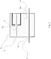
- Figure 1 shows a deposition chamber 2 having a substrate 1 in the bottom part of the deposition chamber 2 and an atomizer 4 arranged in the upper part of the deposition chamber 2.
- the deposition chamber 2 is a closed deposition chamber such that there are openings 6 only for the substrate 1 to enter and exit the deposition chamber 2 and an opening 5 for aerosol exit on the ceiling of the deposition chamber 2.
- the openings 6 are preferably controlled by for example a gas flow in the opening.
- the atomizer 4 can be different than what is shown in this figure and the method according to the invention is not limited to a specific way of creating saturated aerosol.
- the at least one liquid precursor is atomized in two atomizing heads that are arranged in a vertical direction such that the heads are facing toward each other.
- the aerosol jets collide each other in a collision point in a midpoint from the opposing atomizing heads.
- the collision creates first a planar aerosol plane 3a which spreads radially and symmetrically in the deposition chamber 2.
- the atomizers are arranged in the middle of the deposition chamber so that the saturated aerosol will spread uniformly in the chamber but the atomizers can also be placed in another position which affects the spreading of the saturated aerosol and generate a large and slow aerosol whirl having the dimensions of the whole deposition chamber 2.
- Figure 1 shows a starting point for the process.
- Figure 2 shows what takes place in the deposition chamber 2 when the deposition chamber 2 is filled with aerosol such that saturated aerosol is created.
- the two atomizers 4 continuously atomize liquid precursor into liquid droplets such that a planar aerosol plane 3a is produced.
- the produced aerosol plane 3a spreads in the deposition chamber 2 and unites with other aerosol planes 3a so that the deposition aerosol flux 3b is formed.
- the deposition chamber 2 is full of aerosol it becomes also saturated.
- the saturated aerosol falls down to the bottom part of the deposition chamber 2 where the substrate 1 is arranged and the droplets of the saturated aerosol are gravitationally settled on the surface of the substrate to form a thin film on the surface of the substrate 1.
- the atomizers 4 produce planar aerosol planes 3a continuously and the gravitation affects to the produced planar aerosol planes 3a which finally fill the deposition chamber 2 and become saturated.
- the saturated aerosol falls down in the deposition chamber 2 toward the substrate.
- This continuous aerosol output creates a bigger and bigger aerosol flux 3b that eventually becomes saturated.
- the aerosol falls towards the surface of the substrate 1 on the bottom of the deposition chamber 2.
- the substrate 1 may be stationary in the deposition chamber 2 or it may be moved through the deposition chamber 2 and through the saturated aerosol.
- the coating of the substrate 1 is arranged in the deposition chamber 2 in which the aerosol is in a saturated state and therefore the droplets do not dry up, i.e. evaporate.
Landscapes
- Application Of Or Painting With Fluid Materials (AREA)
Claims (13)
- Procédé pour revêtir un substrat (1) dans une chambre de déposition (2), caractérisé en ce que le procédé comprend les étapes consistant à- fournir une source d'au moins un précurseur liquide ;- atomiser ledit au moins un précurseur liquide en gouttelettes liquides dans deux têtes d'atomisation ;- disposer dans la partie supérieure ou dans le centre de la chambre de déposition (2) les deux têtes d'atomisation, l'une tournée vers l'autre de manière que les jets d'aérosol sortant des têtes d'atomisation entrent en collision à un point de collision de manière à créer un plan d'aérosol uni qui s'étend dans un sens essentiellement horizontal dans la chambre de déposition ;- remplir d'aérosol la chambre de déposition (2) pour former un aérosol saturé dans la chambre de déposition (2) ; et- déposer par gravitation l'aérosol saturé vers une surface du substrat (1) pour revêtir le substrat (1) dans la partie inférieure de la chambre de déposition (2).
- Procédé selon la revendication 1, caractérisé en ce qu'une taille des gouttelettes liquides est inférieure à 25 µm.
- Procédé selon la revendication 1, caractérisé en ce qu'une taille des gouttelettes liquides est inférieure à 10 µm.
- Procédé selon la revendication 1, caractérisé en ce qu'une taille des gouttelettes liquides est comprise entre 1 et 5 µm.
- Procédé selon une revendication précédente quelconque, caractérisé en ce que la chambre de déposition (2) comprend une partie supérieure fermée et des ouvertures (6) pour le substrat (1) dans la partie inférieure de la chambre de déposition (2).
- Procédé selon une revendication précédente quelconque, caractérisé en ce que la chambre de déposition (2) est au moins partiellement ouverte du côté supérieur de la chambre de déposition (2).
- Procédé selon une revendication précédente quelconque, caractérisé en ce que le procédé comprend également une étape consistant à- éliminer ou recycler une partie résiduelle de l'aérosol saturé de la chambre de déposition (2) après avoir revêtu le substrat.
- Procédé selon une revendication précédente quelconque, caractérisé en ce que le procédé comprend une étape consistant à- récupérer le précurseur déposé sur le fond de la chambre de déposition (2) pour éliminer ou recycler le précurseur ; et/ou- récupérer le précurseur déposé sur les parois de la chambre de déposition (2) pour éliminer ou recycler le précurseur.
- Procédé selon une revendication précédente quelconque, caractérisé en ce que le procédé comprend une étape consistant à- évacuer un aérosol excédentaire de la chambre de déposition (2) à travers une ouverture (5) et séparer le précurseur de l'aérosol excédentaire pour éliminer ou recycler le précurseur.
- Procédé selon une revendication précédente quelconque, caractérisé en ce que le procédé comprend également une étape consistant à- disposer le substrat (1) dans la partie inférieure de la chambre de déposition (2).
- Procédé selon des revendications précédentes, caractérisé par une étape consistant à:- disposer le substrat (1) de manière qu'il passe à travers l'aérosol saturé.
- Procédé selon l'une quelconque des revendications précédentes, caractérisé par une étape consistant à:- revêtir le substrat (1) en déposant les gouttelettes liquides de l'aérosol saturé vers la surface du substrat (1) pour former un film mince par les gouttelettes sur la surface du substrat (1).
- Procédé selon une revendication précédente quelconque, caractérisé en ce que l'aérosol saturé comprend 0,5 à 4 % en volume de matériau de revêtement.
Applications Claiming Priority (2)
| Application Number | Priority Date | Filing Date | Title |
|---|---|---|---|
| FI20135904A FI125920B (en) | 2013-09-09 | 2013-09-09 | A method of coating a substrate |
| PCT/FI2014/050668 WO2015033021A1 (fr) | 2013-09-09 | 2014-09-02 | Procédé de revêtement de substrat |
Publications (3)
| Publication Number | Publication Date |
|---|---|
| EP3049192A1 EP3049192A1 (fr) | 2016-08-03 |
| EP3049192A4 EP3049192A4 (fr) | 2017-05-10 |
| EP3049192B1 true EP3049192B1 (fr) | 2019-08-14 |
Family
ID=52627848
Family Applications (1)
| Application Number | Title | Priority Date | Filing Date |
|---|---|---|---|
| EP14841877.5A Not-in-force EP3049192B1 (fr) | 2013-09-09 | 2014-09-02 | Procédé de revêtement de substrat |
Country Status (6)
| Country | Link |
|---|---|
| US (1) | US20160221028A1 (fr) |
| EP (1) | EP3049192B1 (fr) |
| JP (1) | JP6517813B2 (fr) |
| CN (1) | CN105555422B (fr) |
| FI (1) | FI125920B (fr) |
| WO (1) | WO2015033021A1 (fr) |
Families Citing this family (4)
| Publication number | Priority date | Publication date | Assignee | Title |
|---|---|---|---|---|
| CA2899255A1 (fr) * | 2015-07-31 | 2017-01-31 | National Research Council Of Canada | Appareil et methode de depot par aerosol de nanoparticules sur un substrat |
| CN108472683A (zh) * | 2016-02-26 | 2018-08-31 | 倍耐克有限公司 | 改进的涂覆方法和设备 |
| US20190030549A1 (en) * | 2016-02-26 | 2019-01-31 | Beneq Oy | Improved aerosol coating device and method |
| EP3911436B1 (fr) | 2019-01-17 | 2024-07-24 | Shell Internationale Research Maatschappij B.V. | Catalyseur à base de nanoparticules bimétalliques, son utilisation dans une hydrogénation sélective, et procédé de fabrication du catalyseur |
Family Cites Families (31)
| Publication number | Priority date | Publication date | Assignee | Title |
|---|---|---|---|---|
| US3647501A (en) * | 1969-12-23 | 1972-03-07 | Ibm | Method for producing photographic emulsion coatings |
| JPS517499B2 (fr) * | 1972-05-08 | 1976-03-08 | ||
| US4290384A (en) * | 1979-10-18 | 1981-09-22 | The Perkin-Elmer Corporation | Coating apparatus |
| US4656963A (en) * | 1981-09-14 | 1987-04-14 | Takashi Yonehara | Method and apparatus for forming an extremely thin film on the surface of an object |
| JPS61249567A (ja) * | 1985-04-30 | 1986-11-06 | Tokyo Copal Kagaku Kk | 表面改質剤等の塗布液の塗布法 |
| US5138520A (en) * | 1988-12-27 | 1992-08-11 | Symetrix Corporation | Methods and apparatus for material deposition |
| US5194297A (en) * | 1992-03-04 | 1993-03-16 | Vlsi Standards, Inc. | System and method for accurately depositing particles on a surface |
| JPH07204545A (ja) * | 1994-01-25 | 1995-08-08 | Rikiyuu:Kk | 熱加速粒子による表膜方法並びにその装置 |
| US5451260A (en) * | 1994-04-15 | 1995-09-19 | Cornell Research Foundation, Inc. | Method and apparatus for CVD using liquid delivery system with an ultrasonic nozzle |
| JPH0871488A (ja) * | 1994-09-08 | 1996-03-19 | Dainippon Toryo Co Ltd | 塗料回収再利用方法 |
| AU6910096A (en) * | 1995-09-01 | 1997-03-27 | Encapsulation Technology, Llc | Method and apparatus for encapsulating particulates |
| US5882368A (en) * | 1997-02-07 | 1999-03-16 | Vidrio Piiano De Mexico, S.A. De C.V. | Method for coating glass substrates by ultrasonic nebulization of solutions |
| US6045864A (en) * | 1997-12-01 | 2000-04-04 | 3M Innovative Properties Company | Vapor coating method |
| US7066976B2 (en) * | 1998-02-24 | 2006-06-27 | Cabot Corporation | Method for the production of electrocatalyst powders |
| BE1011917A6 (fr) * | 1998-05-14 | 2000-03-07 | Cockerill Rech & Dev | Procede et dispositif pour l'application electrostatique en continu d'une substance en poudre sur un substrat. |
| JP3797037B2 (ja) * | 1998-12-04 | 2006-07-12 | 東陶機器株式会社 | 光触媒性親水性コーティング組成物 |
| JP2002102760A (ja) * | 2000-09-29 | 2002-04-09 | Nippon Paint Co Ltd | 水性塗料回収方法 |
| JP2002173782A (ja) * | 2000-12-05 | 2002-06-21 | Auto Network Gijutsu Kenkyusho:Kk | 薄膜成膜装置および薄膜成膜方法 |
| ITBO20030032U1 (it) * | 2003-03-28 | 2004-09-29 | Cefla Soc Coop Arl | Impianto autopulente per il recupero a secco delle nebbie di lavorazionee nelle macchine automatiche per la spruzzatura di vernici acriliche con essicazione uv o di altri prodotti che comportano analoghe esigenz |
| DE102004001095A1 (de) * | 2004-01-05 | 2005-07-28 | Blue Membranes Gmbh | Hochfrequenzzerstäubungsvorrichtung |
| US7462242B2 (en) * | 2004-06-21 | 2008-12-09 | Mystic Tan, Inc. | Misting apparatus for electrostatic application of coating materials to body surfaces |
| US20080317967A1 (en) * | 2005-02-14 | 2008-12-25 | Kwang-Leong Choy | Deposition of Polymeric Films |
| DE102005019686B3 (de) * | 2005-04-22 | 2006-04-13 | Schmid Technology Systems Gmbh | Einrichtung und Verfahren zum Aufbringen einer gleichmäßigen, dünnen Flüssigkeitsschicht auf Substrate |
| US7892593B2 (en) * | 2006-06-27 | 2011-02-22 | Ingo Werner Scheer | Process for coating a substrate |
| WO2008121793A1 (fr) * | 2007-03-30 | 2008-10-09 | The Penn State Research Foundation | Fabrication de dispositifs à points quantiques par dépôt de brouillard |
| FI122502B (fi) * | 2007-12-20 | 2012-02-29 | Beneq Oy | Menetelmä ja laite lasin pinnoittamiseksi |
| FI121990B (fi) * | 2007-12-20 | 2011-07-15 | Beneq Oy | Laite sumun ja hiukkasten tuottamiseksi |
| US9032905B2 (en) * | 2010-06-21 | 2015-05-19 | Beneq Oy | Apparatus and method for coating glass substrate |
| DE102010055042B4 (de) * | 2010-12-17 | 2013-06-06 | Eads Deutschland Gmbh | Verfahren und Vorrichtung zur Bildung eines Elektrolytfilmes auf einer Elektrodenoberfläche |
| JP2013099472A (ja) * | 2011-11-09 | 2013-05-23 | Penta−C株式会社 | 噴霧方法及び室内噴霧装置 |
| ES2602318T3 (es) * | 2011-12-29 | 2017-02-20 | Sumitomo Chemical Company Limited | Dispositivo de atomización ultrasónica y método de control de plagas |
-
2013
- 2013-09-09 FI FI20135904A patent/FI125920B/en not_active IP Right Cessation
-
2014
- 2014-09-02 US US14/915,676 patent/US20160221028A1/en not_active Abandoned
- 2014-09-02 EP EP14841877.5A patent/EP3049192B1/fr not_active Not-in-force
- 2014-09-02 CN CN201480049563.8A patent/CN105555422B/zh not_active Expired - Fee Related
- 2014-09-02 WO PCT/FI2014/050668 patent/WO2015033021A1/fr not_active Ceased
- 2014-09-02 JP JP2016539600A patent/JP6517813B2/ja not_active Expired - Fee Related
Non-Patent Citations (1)
| Title |
|---|
| None * |
Also Published As
| Publication number | Publication date |
|---|---|
| EP3049192A1 (fr) | 2016-08-03 |
| WO2015033021A1 (fr) | 2015-03-12 |
| FI125920B (en) | 2016-04-15 |
| JP2016531749A (ja) | 2016-10-13 |
| CN105555422B (zh) | 2017-09-15 |
| US20160221028A1 (en) | 2016-08-04 |
| JP6517813B2 (ja) | 2019-05-22 |
| EP3049192A4 (fr) | 2017-05-10 |
| FI20135904L (fi) | 2015-03-10 |
| CN105555422A (zh) | 2016-05-04 |
Similar Documents
| Publication | Publication Date | Title |
|---|---|---|
| EP3049192B1 (fr) | Procédé de revêtement de substrat | |
| US5110618A (en) | Process for electrostatically coating a substrate using an aerosol | |
| US3110626A (en) | Apparatus for coating discrete solid material | |
| Filipovic et al. | Methods of simulating thin film deposition using spray pyrolysis techniques | |
| Jones | Solution and suspension layering | |
| US9987642B2 (en) | Apparatus and method for producing aerosol and a focusing part | |
| CN106985378A (zh) | 增材沉积系统和方法 | |
| CN110769941B (zh) | 雾涂敷成膜装置的涂敷头及其维护方法 | |
| CN102695564B (zh) | 用于涂覆基底的设备和方法 | |
| CN106985377A (zh) | 增材沉积系统和方法 | |
| Yang et al. | Coalescence, evaporation and particle deposition of consecutively printed colloidal drops | |
| US20030044524A1 (en) | Vibratory electrostatic fluidized bed for powder paint coating | |
| JPS6242674B2 (fr) | ||
| US6485568B1 (en) | Apparatus for coating substrates with materials, particularly for lacquering si-wafers | |
| Mühlig et al. | Nanometre-sized droplets from a gas dynamic virtual nozzle | |
| US20190030549A1 (en) | Improved aerosol coating device and method | |
| KR101230241B1 (ko) | 세라믹 분말 에어로졸 증착 방법 | |
| EP2799153B1 (fr) | Système et procédé d'humidification d'un système pour appliquer un revêtement sur une pièce | |
| JPH02229562A (ja) | 液体又は溶融体の粒子の生成塗布方法 | |
| US20190030562A1 (en) | Improved coating process and apparatus | |
| Alavi et al. | Experimental study and particle population modeling of coating in a jet-fluidized bed | |
| SU402191A1 (ru) | Способ нанесения пленки материала на прессованные заготовки | |
| KR20120054794A (ko) | 세라믹 분말 에어로졸 증착 방법 | |
| Muliadi et al. | Evaluation of Spray Characteristics in Pharmaceutical Tablet Coating Processes: The Influences of Drum Rotational Speed and Drying Air Flow Rate |
Legal Events
| Date | Code | Title | Description |
|---|---|---|---|
| PUAI | Public reference made under article 153(3) epc to a published international application that has entered the european phase |
Free format text: ORIGINAL CODE: 0009012 |
|
| 17P | Request for examination filed |
Effective date: 20160323 |
|
| AK | Designated contracting states |
Kind code of ref document: A1 Designated state(s): AL AT BE BG CH CY CZ DE DK EE ES FI FR GB GR HR HU IE IS IT LI LT LU LV MC MK MT NL NO PL PT RO RS SE SI SK SM TR |
|
| AX | Request for extension of the european patent |
Extension state: BA ME |
|
| RIN1 | Information on inventor provided before grant (corrected) |
Inventor name: VIRTANEN, SAULI Inventor name: TAMMELA, SIMO Inventor name: ALITALO, VILLE Inventor name: ASIKKALA, KAI |
|
| DAX | Request for extension of the european patent (deleted) | ||
| A4 | Supplementary search report drawn up and despatched |
Effective date: 20170406 |
|
| RIC1 | Information provided on ipc code assigned before grant |
Ipc: B05D 1/30 20060101AFI20170401BHEP Ipc: B05B 1/26 20060101ALI20170401BHEP Ipc: B05D 1/34 20060101ALI20170401BHEP Ipc: B05D 7/00 20060101ALI20170401BHEP |
|
| STAA | Information on the status of an ep patent application or granted ep patent |
Free format text: STATUS: EXAMINATION IS IN PROGRESS |
|
| 17Q | First examination report despatched |
Effective date: 20181002 |
|
| REG | Reference to a national code |
Ref country code: DE Ref legal event code: R079 Ref document number: 602014051888 Country of ref document: DE Free format text: PREVIOUS MAIN CLASS: B05D0001300000 Ipc: B05B0001260000 |
|
| GRAP | Despatch of communication of intention to grant a patent |
Free format text: ORIGINAL CODE: EPIDOSNIGR1 |
|
| STAA | Information on the status of an ep patent application or granted ep patent |
Free format text: STATUS: GRANT OF PATENT IS INTENDED |
|
| RIC1 | Information provided on ipc code assigned before grant |
Ipc: B05D 1/02 20060101ALI20190227BHEP Ipc: B05D 1/30 20060101ALI20190227BHEP Ipc: B05B 1/26 20060101AFI20190227BHEP |
|
| INTG | Intention to grant announced |
Effective date: 20190320 |
|
| RIN1 | Information on inventor provided before grant (corrected) |
Inventor name: ALITALO, VILLE Inventor name: TAMMELA, SIMO Inventor name: ASIKKALA, KAI Inventor name: VIRTANEN, SAULI |
|
| GRAS | Grant fee paid |
Free format text: ORIGINAL CODE: EPIDOSNIGR3 |
|
| GRAA | (expected) grant |
Free format text: ORIGINAL CODE: 0009210 |
|
| STAA | Information on the status of an ep patent application or granted ep patent |
Free format text: STATUS: THE PATENT HAS BEEN GRANTED |
|
| AK | Designated contracting states |
Kind code of ref document: B1 Designated state(s): AL AT BE BG CH CY CZ DE DK EE ES FI FR GB GR HR HU IE IS IT LI LT LU LV MC MK MT NL NO PL PT RO RS SE SI SK SM TR |
|
| REG | Reference to a national code |
Ref country code: GB Ref legal event code: FG4D |
|
| REG | Reference to a national code |
Ref country code: CH Ref legal event code: EP Ref country code: AT Ref legal event code: REF Ref document number: 1166391 Country of ref document: AT Kind code of ref document: T Effective date: 20190815 |
|
| REG | Reference to a national code |
Ref country code: IE Ref legal event code: FG4D |
|
| REG | Reference to a national code |
Ref country code: DE Ref legal event code: R096 Ref document number: 602014051888 Country of ref document: DE |
|
| REG | Reference to a national code |
Ref country code: NL Ref legal event code: FP |
|
| REG | Reference to a national code |
Ref country code: LT Ref legal event code: MG4D |
|
| PG25 | Lapsed in a contracting state [announced via postgrant information from national office to epo] |
Ref country code: BG Free format text: LAPSE BECAUSE OF FAILURE TO SUBMIT A TRANSLATION OF THE DESCRIPTION OR TO PAY THE FEE WITHIN THE PRESCRIBED TIME-LIMIT Effective date: 20191114 Ref country code: SE Free format text: LAPSE BECAUSE OF FAILURE TO SUBMIT A TRANSLATION OF THE DESCRIPTION OR TO PAY THE FEE WITHIN THE PRESCRIBED TIME-LIMIT Effective date: 20190814 Ref country code: NO Free format text: LAPSE BECAUSE OF FAILURE TO SUBMIT A TRANSLATION OF THE DESCRIPTION OR TO PAY THE FEE WITHIN THE PRESCRIBED TIME-LIMIT Effective date: 20191114 Ref country code: LT Free format text: LAPSE BECAUSE OF FAILURE TO SUBMIT A TRANSLATION OF THE DESCRIPTION OR TO PAY THE FEE WITHIN THE PRESCRIBED TIME-LIMIT Effective date: 20190814 Ref country code: PT Free format text: LAPSE BECAUSE OF FAILURE TO SUBMIT A TRANSLATION OF THE DESCRIPTION OR TO PAY THE FEE WITHIN THE PRESCRIBED TIME-LIMIT Effective date: 20191216 Ref country code: HR Free format text: LAPSE BECAUSE OF FAILURE TO SUBMIT A TRANSLATION OF THE DESCRIPTION OR TO PAY THE FEE WITHIN THE PRESCRIBED TIME-LIMIT Effective date: 20190814 Ref country code: FI Free format text: LAPSE BECAUSE OF FAILURE TO SUBMIT A TRANSLATION OF THE DESCRIPTION OR TO PAY THE FEE WITHIN THE PRESCRIBED TIME-LIMIT Effective date: 20190814 |
|
| REG | Reference to a national code |
Ref country code: AT Ref legal event code: MK05 Ref document number: 1166391 Country of ref document: AT Kind code of ref document: T Effective date: 20190814 |
|
| PG25 | Lapsed in a contracting state [announced via postgrant information from national office to epo] |
Ref country code: AL Free format text: LAPSE BECAUSE OF FAILURE TO SUBMIT A TRANSLATION OF THE DESCRIPTION OR TO PAY THE FEE WITHIN THE PRESCRIBED TIME-LIMIT Effective date: 20190814 Ref country code: LV Free format text: LAPSE BECAUSE OF FAILURE TO SUBMIT A TRANSLATION OF THE DESCRIPTION OR TO PAY THE FEE WITHIN THE PRESCRIBED TIME-LIMIT Effective date: 20190814 Ref country code: ES Free format text: LAPSE BECAUSE OF FAILURE TO SUBMIT A TRANSLATION OF THE DESCRIPTION OR TO PAY THE FEE WITHIN THE PRESCRIBED TIME-LIMIT Effective date: 20190814 Ref country code: IS Free format text: LAPSE BECAUSE OF FAILURE TO SUBMIT A TRANSLATION OF THE DESCRIPTION OR TO PAY THE FEE WITHIN THE PRESCRIBED TIME-LIMIT Effective date: 20191214 Ref country code: RS Free format text: LAPSE BECAUSE OF FAILURE TO SUBMIT A TRANSLATION OF THE DESCRIPTION OR TO PAY THE FEE WITHIN THE PRESCRIBED TIME-LIMIT Effective date: 20190814 Ref country code: GR Free format text: LAPSE BECAUSE OF FAILURE TO SUBMIT A TRANSLATION OF THE DESCRIPTION OR TO PAY THE FEE WITHIN THE PRESCRIBED TIME-LIMIT Effective date: 20191115 |
|
| PG25 | Lapsed in a contracting state [announced via postgrant information from national office to epo] |
Ref country code: TR Free format text: LAPSE BECAUSE OF FAILURE TO SUBMIT A TRANSLATION OF THE DESCRIPTION OR TO PAY THE FEE WITHIN THE PRESCRIBED TIME-LIMIT Effective date: 20190814 |
|
| PG25 | Lapsed in a contracting state [announced via postgrant information from national office to epo] |
Ref country code: AT Free format text: LAPSE BECAUSE OF FAILURE TO SUBMIT A TRANSLATION OF THE DESCRIPTION OR TO PAY THE FEE WITHIN THE PRESCRIBED TIME-LIMIT Effective date: 20190814 Ref country code: RO Free format text: LAPSE BECAUSE OF FAILURE TO SUBMIT A TRANSLATION OF THE DESCRIPTION OR TO PAY THE FEE WITHIN THE PRESCRIBED TIME-LIMIT Effective date: 20190814 Ref country code: EE Free format text: LAPSE BECAUSE OF FAILURE TO SUBMIT A TRANSLATION OF THE DESCRIPTION OR TO PAY THE FEE WITHIN THE PRESCRIBED TIME-LIMIT Effective date: 20190814 Ref country code: IT Free format text: LAPSE BECAUSE OF FAILURE TO SUBMIT A TRANSLATION OF THE DESCRIPTION OR TO PAY THE FEE WITHIN THE PRESCRIBED TIME-LIMIT Effective date: 20190814 Ref country code: PL Free format text: LAPSE BECAUSE OF FAILURE TO SUBMIT A TRANSLATION OF THE DESCRIPTION OR TO PAY THE FEE WITHIN THE PRESCRIBED TIME-LIMIT Effective date: 20190814 Ref country code: DK Free format text: LAPSE BECAUSE OF FAILURE TO SUBMIT A TRANSLATION OF THE DESCRIPTION OR TO PAY THE FEE WITHIN THE PRESCRIBED TIME-LIMIT Effective date: 20190814 |
|
| REG | Reference to a national code |
Ref country code: DE Ref legal event code: R081 Ref document number: 602014051888 Country of ref document: DE Owner name: GMB GLASMANUFAKTUR BRANDENBURG GMBH, DE Free format text: FORMER OWNER: BENEQ OY, ESPOO, FI |
|
| PG25 | Lapsed in a contracting state [announced via postgrant information from national office to epo] |
Ref country code: IS Free format text: LAPSE BECAUSE OF FAILURE TO SUBMIT A TRANSLATION OF THE DESCRIPTION OR TO PAY THE FEE WITHIN THE PRESCRIBED TIME-LIMIT Effective date: 20200224 Ref country code: MC Free format text: LAPSE BECAUSE OF FAILURE TO SUBMIT A TRANSLATION OF THE DESCRIPTION OR TO PAY THE FEE WITHIN THE PRESCRIBED TIME-LIMIT Effective date: 20190814 Ref country code: SM Free format text: LAPSE BECAUSE OF FAILURE TO SUBMIT A TRANSLATION OF THE DESCRIPTION OR TO PAY THE FEE WITHIN THE PRESCRIBED TIME-LIMIT Effective date: 20190814 Ref country code: CZ Free format text: LAPSE BECAUSE OF FAILURE TO SUBMIT A TRANSLATION OF THE DESCRIPTION OR TO PAY THE FEE WITHIN THE PRESCRIBED TIME-LIMIT Effective date: 20190814 Ref country code: SK Free format text: LAPSE BECAUSE OF FAILURE TO SUBMIT A TRANSLATION OF THE DESCRIPTION OR TO PAY THE FEE WITHIN THE PRESCRIBED TIME-LIMIT Effective date: 20190814 |
|
| REG | Reference to a national code |
Ref country code: CH Ref legal event code: PL |
|
| REG | Reference to a national code |
Ref country code: DE Ref legal event code: R097 Ref document number: 602014051888 Country of ref document: DE |
|
| REG | Reference to a national code |
Ref country code: GB Ref legal event code: 732E Free format text: REGISTERED BETWEEN 20200604 AND 20200610 |
|
| PLBE | No opposition filed within time limit |
Free format text: ORIGINAL CODE: 0009261 |
|
| STAA | Information on the status of an ep patent application or granted ep patent |
Free format text: STATUS: NO OPPOSITION FILED WITHIN TIME LIMIT |
|
| REG | Reference to a national code |
Ref country code: NL Ref legal event code: PD Owner name: GMB GLASMANUFAKTUR BRANDENBURG GMBH; DE Free format text: DETAILS ASSIGNMENT: CHANGE OF OWNER(S), ASSIGNMENT; FORMER OWNER NAME: BENEQ OY Effective date: 20200701 |
|
| PG2D | Information on lapse in contracting state deleted |
Ref country code: IS |
|
| PG25 | Lapsed in a contracting state [announced via postgrant information from national office to epo] |
Ref country code: LI Free format text: LAPSE BECAUSE OF NON-PAYMENT OF DUE FEES Effective date: 20190930 Ref country code: CH Free format text: LAPSE BECAUSE OF NON-PAYMENT OF DUE FEES Effective date: 20190930 Ref country code: IE Free format text: LAPSE BECAUSE OF NON-PAYMENT OF DUE FEES Effective date: 20190902 Ref country code: LU Free format text: LAPSE BECAUSE OF NON-PAYMENT OF DUE FEES Effective date: 20190902 |
|
| REG | Reference to a national code |
Ref country code: BE Ref legal event code: MM Effective date: 20190930 |
|
| 26N | No opposition filed |
Effective date: 20200603 |
|
| PG25 | Lapsed in a contracting state [announced via postgrant information from national office to epo] |
Ref country code: BE Free format text: LAPSE BECAUSE OF NON-PAYMENT OF DUE FEES Effective date: 20190930 Ref country code: SI Free format text: LAPSE BECAUSE OF FAILURE TO SUBMIT A TRANSLATION OF THE DESCRIPTION OR TO PAY THE FEE WITHIN THE PRESCRIBED TIME-LIMIT Effective date: 20190814 |
|
| PGFP | Annual fee paid to national office [announced via postgrant information from national office to epo] |
Ref country code: NL Payment date: 20200926 Year of fee payment: 7 Ref country code: DE Payment date: 20200929 Year of fee payment: 7 Ref country code: GB Payment date: 20200928 Year of fee payment: 7 Ref country code: FR Payment date: 20200925 Year of fee payment: 7 |
|
| PG25 | Lapsed in a contracting state [announced via postgrant information from national office to epo] |
Ref country code: CY Free format text: LAPSE BECAUSE OF FAILURE TO SUBMIT A TRANSLATION OF THE DESCRIPTION OR TO PAY THE FEE WITHIN THE PRESCRIBED TIME-LIMIT Effective date: 20190814 |
|
| PG25 | Lapsed in a contracting state [announced via postgrant information from national office to epo] |
Ref country code: MT Free format text: LAPSE BECAUSE OF FAILURE TO SUBMIT A TRANSLATION OF THE DESCRIPTION OR TO PAY THE FEE WITHIN THE PRESCRIBED TIME-LIMIT Effective date: 20190814 Ref country code: HU Free format text: LAPSE BECAUSE OF FAILURE TO SUBMIT A TRANSLATION OF THE DESCRIPTION OR TO PAY THE FEE WITHIN THE PRESCRIBED TIME-LIMIT; INVALID AB INITIO Effective date: 20140902 |
|
| REG | Reference to a national code |
Ref country code: DE Ref legal event code: R119 Ref document number: 602014051888 Country of ref document: DE |
|
| REG | Reference to a national code |
Ref country code: NL Ref legal event code: MM Effective date: 20211001 |
|
| GBPC | Gb: european patent ceased through non-payment of renewal fee |
Effective date: 20210902 |
|
| PG25 | Lapsed in a contracting state [announced via postgrant information from national office to epo] |
Ref country code: NL Free format text: LAPSE BECAUSE OF NON-PAYMENT OF DUE FEES Effective date: 20211001 Ref country code: MK Free format text: LAPSE BECAUSE OF FAILURE TO SUBMIT A TRANSLATION OF THE DESCRIPTION OR TO PAY THE FEE WITHIN THE PRESCRIBED TIME-LIMIT Effective date: 20190814 |
|
| PG25 | Lapsed in a contracting state [announced via postgrant information from national office to epo] |
Ref country code: GB Free format text: LAPSE BECAUSE OF NON-PAYMENT OF DUE FEES Effective date: 20210902 Ref country code: FR Free format text: LAPSE BECAUSE OF NON-PAYMENT OF DUE FEES Effective date: 20210930 Ref country code: DE Free format text: LAPSE BECAUSE OF NON-PAYMENT OF DUE FEES Effective date: 20220401 |