EP3049615B1 - Appareil pour puits et son procédé d'utilisation dans la production de gaz - Google Patents
Appareil pour puits et son procédé d'utilisation dans la production de gaz Download PDFInfo
- Publication number
- EP3049615B1 EP3049615B1 EP14772192.2A EP14772192A EP3049615B1 EP 3049615 B1 EP3049615 B1 EP 3049615B1 EP 14772192 A EP14772192 A EP 14772192A EP 3049615 B1 EP3049615 B1 EP 3049615B1
- Authority
- EP
- European Patent Office
- Prior art keywords
- nozzles
- production tubing
- water
- well apparatus
- fin
- Prior art date
- Legal status (The legal status is an assumption and is not a legal conclusion. Google has not performed a legal analysis and makes no representation as to the accuracy of the status listed.)
- Active
Links
Images


Classifications
-
- E—FIXED CONSTRUCTIONS
- E21—EARTH OR ROCK DRILLING; MINING
- E21B—EARTH OR ROCK DRILLING; OBTAINING OIL, GAS, WATER, SOLUBLE OR MELTABLE MATERIALS OR A SLURRY OF MINERALS FROM WELLS
- E21B37/00—Methods or apparatus for cleaning boreholes or wells
-
- E—FIXED CONSTRUCTIONS
- E21—EARTH OR ROCK DRILLING; MINING
- E21B—EARTH OR ROCK DRILLING; OBTAINING OIL, GAS, WATER, SOLUBLE OR MELTABLE MATERIALS OR A SLURRY OF MINERALS FROM WELLS
- E21B17/00—Drilling rods or pipes; Flexible drill strings; Kellies; Drill collars; Sucker rods; Cables; Casings; Tubings
- E21B17/10—Wear protectors; Centralising devices, e.g. stabilisers
- E21B17/1078—Stabilisers or centralisers for casing, tubing or drill pipes
-
- E—FIXED CONSTRUCTIONS
- E21—EARTH OR ROCK DRILLING; MINING
- E21B—EARTH OR ROCK DRILLING; OBTAINING OIL, GAS, WATER, SOLUBLE OR MELTABLE MATERIALS OR A SLURRY OF MINERALS FROM WELLS
- E21B21/00—Methods or apparatus for flushing boreholes, e.g. by use of exhaust air from motor
- E21B21/14—Methods or apparatus for flushing boreholes, e.g. by use of exhaust air from motor using liquids and gases, e.g. foams
-
- E—FIXED CONSTRUCTIONS
- E21—EARTH OR ROCK DRILLING; MINING
- E21B—EARTH OR ROCK DRILLING; OBTAINING OIL, GAS, WATER, SOLUBLE OR MELTABLE MATERIALS OR A SLURRY OF MINERALS FROM WELLS
- E21B34/00—Valve arrangements for boreholes or wells
- E21B34/06—Valve arrangements for boreholes or wells in wells
-
- E—FIXED CONSTRUCTIONS
- E21—EARTH OR ROCK DRILLING; MINING
- E21B—EARTH OR ROCK DRILLING; OBTAINING OIL, GAS, WATER, SOLUBLE OR MELTABLE MATERIALS OR A SLURRY OF MINERALS FROM WELLS
- E21B37/00—Methods or apparatus for cleaning boreholes or wells
- E21B37/06—Methods or apparatus for cleaning boreholes or wells using chemical means for preventing or limiting, e.g. eliminating, the deposition of paraffins or like substances
-
- E—FIXED CONSTRUCTIONS
- E21—EARTH OR ROCK DRILLING; MINING
- E21B—EARTH OR ROCK DRILLING; OBTAINING OIL, GAS, WATER, SOLUBLE OR MELTABLE MATERIALS OR A SLURRY OF MINERALS FROM WELLS
- E21B41/00—Equipment or details not covered by groups E21B15/00 - E21B40/00
- E21B41/0078—Nozzles used in boreholes
-
- E—FIXED CONSTRUCTIONS
- E21—EARTH OR ROCK DRILLING; MINING
- E21B—EARTH OR ROCK DRILLING; OBTAINING OIL, GAS, WATER, SOLUBLE OR MELTABLE MATERIALS OR A SLURRY OF MINERALS FROM WELLS
- E21B43/00—Methods or apparatus for obtaining oil, gas, water, soluble or meltable materials or a slurry of minerals from wells
- E21B43/12—Methods or apparatus for controlling the flow of the obtained fluid to or in wells
- E21B43/121—Lifting well fluids
-
- E—FIXED CONSTRUCTIONS
- E21—EARTH OR ROCK DRILLING; MINING
- E21B—EARTH OR ROCK DRILLING; OBTAINING OIL, GAS, WATER, SOLUBLE OR MELTABLE MATERIALS OR A SLURRY OF MINERALS FROM WELLS
- E21B43/00—Methods or apparatus for obtaining oil, gas, water, soluble or meltable materials or a slurry of minerals from wells
- E21B43/16—Enhanced recovery methods for obtaining hydrocarbons
Definitions
- the present invention relates to well apparatus and a method for use in gas production from underground reservoirs. Particularly, but not exclusively, the present invention relates to a lower completion component for use as part of a downhole tool assembly.
- Wells used in the production of gas may also produce quantities of water and gas condensate. Some of these gas wells are affected by halite scale, which deposits on wellbore tubulars and may also deposit within the reservoir rock near the wellbore. This halite scale has the potential to restrict gas flow and may cause a complete blockage of the well in extreme conditions.
- halite scale deposition is the de-hydration of highly saline formation waters by natural gas as the gas flows into the near wellbore region or the well itself. If the water that lies below or within the gas reservoir is highly saline, it may take only a small amount of de-hydration to take the water past salt saturation, resulting in halite being precipitated out of solution. De-hydration occurs because, as gas expands (as it does when it flows from a high pressure reservoir into a low pressure well), its capacity to hold water increases.
- One way that has been used in the past to prevent the salt dropping out is to introduce fresh (or low salinity) water to the well. This fresh water dilutes the brine so that any water evaporation maintains the brine in an under saturated state.
- the well apparatus includes production tubing including an injector for the injection of an inhibitor chemical when scale precipitation is detected.
- water in a liquid form may have a significant residence time in the well (in the form of travel time up the wellbore) before being evaporated by the natural gas. This can lead to significant deposition at the bottom of the well.
- the present invention seeks to address these and other problems arising from halite deposition during gas production.
- the present invention also seeks to provide an apparatus and method for reducing halite deposition during gas production.
- the present invention further seeks to provide an apparatus and method for delivering water having a lower salinity than the salinity of formation water present in the gas reservoir to one or more gas inflow sites in a well during gas production.
- the present invention further seeks to provide an apparatus and method for delivering low salinity water in a manner that dilutes the saline formation water and promotes the uptake of the introduced low salinity water by the gas on expansion in preference to the saline formation water.
- the present invention therefore provides well apparatus for use in gas production, the well apparatus comprising a production tubing having a gas inlet; a water distribution pipe disposed on the production tubing; and a plurality of separate nozzles in fluid communication with the water distribution pipe wherein the plurality of nozzles are adapted to inject fine water droplets around the exterior of the production tubing and the plurality of nozzles are spatially distributed axially and circumferentially on the production tubing.
- the well apparatus further comprises a fin extending radially outwardly from the production tubing and wherein the plurality of nozzles is mounted on the fin.
- the fin describes a helical path around the production tubing.
- the nozzles may be arranged such that water is injected by the nozzles substantially tangentially to the circumference of the production tubing.
- the fin has first and second substantially parallel side walls and the water distribution pipe is mounted on the upwardly facing side wall of the fin. More preferably the plurality of nozzles is arranged such that their nozzle outlets are in the side wall of the fin that has the greater intimate contact with the gas flow. Ideally the nozzle outlets project through the downwardly facing side wall of the fin.
- the fin and the accompanying plurality of nozzles extend at least 180° around the production tubing, more preferably at least 270°.
- the well apparatus may further comprise at least one upper nozzle in fluid communication with the water distribution pipe, the at least one upper nozzle being adapted to inject water into the interior of the production tubing. Also, the well apparatus may additionally include a valve in fluid communication with the water distribution pipe for controlling the supply of water to the plurality of nozzles.
- the plurality of nozzles is adapted to generate a substantially atomized mist of water particles.
- the plurality of nozzles is disposed below the gas inlet. Also one or more of the plurality of nozzles may be disposed adjacent the gas inlet.
- the gas inlet may comprise a perforated region of the production tubing or may comprise a ceramic sand screen. Also the perforated region may be above and separate from the region of the production tubing on which the fin is mounted.
- the present invention further provides a method of limiting halite deposition in a well during gas production, the method comprising positioning a production tubing in a gas reservoir and injecting water into the region surrounding the production tubing during gas production, wherein the water is injected into the region surrounding the production tubing using a plurality of nozzles in fluid communication with a water distribution line, the plurality of nozzles being spatially distributed axially and circumferentially on the production tubing.
- the present invention is preferably a lower completion component that may be stand alone, part of a system or modified to form a system for use in gas producing wells.
- the present invention is a water distribution component adapted to function as a gas reservoir humidifier.
- the present invention is adapted to deliver low salinity water to an area of gas production so as to control salt deposition in the gas well.
- the present invention produces fine water droplets, preferably substantially atomised water particles, at or near the wellbore which are easily evaporated by the gas as the gas expands. Furthermore, this fine mist of water injected at or near the wellbore is much less likely to reside at the bottom of the well, and any excess is easily extracted to the surface.
- reference herein to 'lower' and 'below' is intended as reference to components and features of the apparatus that are deeper in the well relative to 'upper' components and features that are 'above' and consequently closer to the entrance to the well (wellhead).
- reference herein to 'downwardly facing' is reference to a component facing approximately away from the wellhead, whereas reference herein to 'upwardly facing' is reference to a component facing approximately towards the wellhead.
- a wellbore casing 1 is shown with a plurality of perforations 2 providing fluid communication between the interior of the wellbore casing 1 and an underground gas reservoir 3.
- the apparatus is a lower completion component 4 which will be referred to herein as a reservoir humidifier tool.
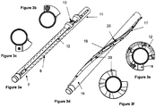
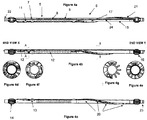
- the reservoir humidifier tool 4 comprises an upper section 5 and a lower section 6 each of which will be described in greater detail below with reference to Figures 3a to 3f and Figures 4a to 4g .
- the upper and lower sections 5, 6 of the reservoir humidifier tool may be manufactured as a single unitary component or as two separate interconnecting components. In the latter case, interconnection of the upper and lower sections is achieved using any conventional means for example, but not limited to, a threaded coupling.
- the metallurgy of the two sections 5, 6 is selected in dependence upon expected downhole conditions. Several factors may contribute to the selection of the material for the base pipe including, but not limited to: gas composition; temperature; pressure; the expected longevity or lifetime of the completion; and, whether the water to be injected by the reservoir humidifier tool is to de de-oxygenated. In some environments L80 carbon steel may be appropriate, but if high chlorides and CO 2 are likely to be present then L80 carbon steel with 13% chrome or possibly 28% chrome with a high nickel content may be used instead. Similarly, for other expected downhole environments materials different to those mentioned above may be used for the upper and lower sections 5, 6.
- the base pipe 7 of the upper section 5 of the reservoir humidifier tool includes a perforated region 8.
- the perforated region 8 has a plurality of pre-drilled holes 9 extending through the thickness of the pipe 7 to allow gas flow from the annulus 10 of the casing 1 to the inside of the tool.
- the drilled holes 9 are arranged in an array along the length and circumference of the perforated region 8 with the axial length of the perforated region 8 and the cumulative open flow area of the holes being determined with respect to expected gas flow rates, the spatial distribution of the perforations being determined so as to minimize loss of base pipe tensile strength.
- the array of drilled holes 9 need not be continuous.
- one or more axially extending un-perforated channels may be provided where capillary lines run to minimise erosive damage.
- the upper section 5 further includes an injection valve 11 mounted in a housing on the exterior of the base pipe 7.
- the injection valve 11 is preferably conventional in design and is used to control the release of water by the reservoir humidifier tool. A detailed description of a conventional injection valve may be found in WO2011/043872 the total content of which is incorporated herein by reference.
- the injection valve 11 is in liquid communication with a water distribution pipe in the form of an encapsulated capillary line 12 which delivers water to the injection valve 11 and beyond (see below).
- the capillary line 12, and all other tool fittings is preferably, but not exclusively, made of 1/4" or 3/8" (6.35 mm or 9.53 mm) SS316L stainless steel but alternative sizing or metallurgy may be selected subject to the expected downhole conditions and pressure drops expected.
- Duplex 2205, Super Duplex 2507, an Inconel alloy 625 or even Hastelloy C-275 may be used instead.
- an upper nozzle 13 Adjacent the injection valve 11 an upper nozzle 13 is provided which is in fluid communication with and downstream of the injection valve 11.
- the upper nozzle 13 is either mounted on the interior wall of the base pipe 7 or projects through an aperture in the base pipe 7 into the interior of the base pipe 7. In both cases the upper nozzle 13 is arranged to deliver fine water droplets, preferably an atomised water mist, to the gas flow path in the interior of the base pipe 7.
- the upper nozzle 13 comprises an impingement or impellar type jet made, for example, of tungsten carbide or a similar wear resistant material. The size of the nozzle orifice or outlet is selected in dependence on the desired flow rate and pressure of the water achievable by the tool.
- the nozzle outlet is expected to be in the range 0.01-0.02 mm diameter and this accommodates total system flow rates in the range 0.1 to 2 litres per minute (divided by the total number of nozzles supplied by the capillary line 12.
- Nozzle pressures in the range 689-1724 kPa (100-250 psi) are preferable but lower pressure nozzles may alternatively be necessary where surface application pressure is limited.
- the nozzle 13 (and any one or more of the lower nozzles described below) may be poppet mounted, allowing the nozzle to be by-passed should higher water flow rates be required (for tubing flush or formation soak) by increasing injection pressure past the poppet threshold.
- an upper finned centraliser 14 is provided at the upper end of the upper section 5.
- the centraliser 14 includes a plurality of radially outwardly extending fins with outer abutment surfaces for contact with the inner surface of the wellbore casing 1 or the wall of the well so as to ensure proper centralised alignment of the wellbore. Sufficient clearance is provided in order for the tool to fit within the well architecture, as per standard oilfield practice.
- Axially extending channels are formed between pairs of adjacent fins to allow axial passage of capillary lines 12 and any capillary line splices.
- the centraliser 14 which is preferably conventional in design, may be a separate sleeve type component that slips on over the base pipe 7. Alternatively the centraliser 14 may be welded to or machined from the base pipe 7. In some instances, the centralizer may be replaced or enhanced by an annulus isolation packer in order to provide zonal isolation. This packer may have hydraulic feed-throughs in order to allow the passage of the water supply to the lower tools. In a further alternative, a swell type packer may be utilized.
- the lower section 6 of the reservoir humidifier tool includes a base pipe 15 which is axially aligned with, and optionally integrally formed with, the base pipe 7 of the upper section 5.
- the metallurgy of the lower section's base pipe 15 is dependent upon the expected downhole environment.
- the lower section 6 preferably includes a centraliser 16 which is identical or very similar to the centraliser 14 of the upper section 5.
- the lower centraliser 16 is mounted at the lowermost end of the lower section 6 and so, in combination with the upper centraliser 14, ensures the lower completion remains axially aligned and centralised within the well.
- the humidifier fin 17 Provided on the outside of the base pipe 15 of the lower section 6 is one or more radially outwardly extending humidifier fins 17 (one fin is shown in the figures).
- the at least one fin 17 is positioned so as to be substantially aligned with the apertures in the wellbore casing.
- the humidifier fin 17 follows a helical path around the outside of the base pipe 15 and thereby encourages a corresponding helical gas flow around the outside of the base pipe 15.
- the humidifier fin 17 extends approx. 350° around the base pipe 15. This leaves a straight line path from adjacent the injection valve 11 to the next tool. This ensures the humidifier fin 17 is not a barrier to the passage of a subsequent supply line to a lower tool.
- the humidifier fin 17 is substantially solid with the exterior surfaces of the fin 17 consisting of a pair of substantially parallel continuous side walls 18 that extend outwardly substantially orthogonal to the outer surface of the base pipe 15 and an upper wall 19 which bridges the radially outermost edges of the two side walls 18.
- the capillary line 12 is mounted to one of the side walls 18 which provides physical protection to the capillary line 12 while being run in hole and provides protection to the capillary line 12 from erosional damage during gas production.
- the capillary line 12 is mounted to the upwardly facing side wall 18 of the fin 17.
- the fin 17 may be hollow and adapted to accommodate the capillary line 12 within it.
- the humidifier fin 17 may be bolted, welded or machined to the base pipe 15 and may be formed of the same material as the base pipe or of a different material that is unreactive with the downhole environment e.g. a metallic material, silicon-based material, rubberised material or TeflonTM-type material.
- a plurality of lower nozzles 20 are mounted within the humidifier fin 17 and so are arranged to direct fine water droplets, preferably an atomised water mist, laterally (i.e. tangentially to the circumference of the base pipe 15) directly into the path of the gas flow.
- the lower nozzles 20 are separated from one another, preferably at regular intervals, another along the length of the fin 17.
- the nozzles 20 may be positioned so as to be substantially aligned with the apertures in the wellbore casing.
- the plurality of nozzles 20 preferably extend at least 180° around the base pipe 15 and more preferably 270°.
- the plurality of lower nozzles 20 are mounted in the fin 17 with their nozzle outlets all facing substantially in the same direction.
- the nozzle outlets are located in apertures in the side wall 18 on the side of the helix that has greater intimate contact with the gas flow around the outside of the base pipe 15.
- the downwardly facing wall of the fin (the side facing the outside of the helix) will have greatest intimate contact with the high pressure high flow rate stream whereas the upwardly facing wall of the fin (the side facing the inside of the helix) will be in a lower pressure, lower flow rate zone.
- the nozzle outlets will be in the side wall facing towards the gas flow from above, i.e. the downwardly facing side wall 18.
- the humidifier fin 17 causes the gas to flow past the lower nozzle outlets thereby maximising water droplet and gas mixing.
- Each lower nozzle 20 is the same as or similar to the upper nozzle 13 and each is connected to the capillary line 12 by means of a T-junction.
- the injection valve 11 controls the supply of water to, and the one capillary line 12 delivers water to, a plurality of nozzles 13, 20 which are distributed axially and circumferentially around the lower completion.
- the angle of the helix described by the humidifier fin 17 is sufficiently shallow to ensure the lower nozzles are well distributed across the lower section 6 whilst minimising high fluid pressure losses that can arise from such a convoluted flow path.
- the lowermost lower nozzle 21 also constitutes termination of the capillary line 12.
- a conventional tool box 22 (not shown) is provided for connection to a second reservoir humidifier tool or to production tubing.
- a conventional tool pin 23 (not shown) is provided for connection to a further reservoir humidifier tool, to other tools or to a bullnose end cap.
- the design and functionality of the tool box 22 and the tool pin 23 are subject to conventional pipe size and connectivity requirements.
- the above description describes a single reservoir humidifier tool 4. It will, of course, be understood that for larger gas production intervals a plurality of reservoir humidifier tools may be connected together, end to end, so as to ensure humidification for a major part, if not all, of the production interval. Similarly, as illustrated in Figure 2 , where a plurality of gas production intervals exist separate by non-productive regions, the lower completion may include a plurality of reservoir humidifier tools 4 connected together, end to end, or connected with intervening production tubing so that each reservoir humidifier tool is aligned with a gas production interval.
- a reservoir humidifier mandrel may have a plurality of capillary lines each supplying water to a different plurality of nozzles.
- the lower section 6 of the humidifier tool 4 has an un-perforated base pipe 15 with a tight tolerance with respect to the wellbore casing. This prevents significant gas expansion at the point of entry to the wellbore, moving the point of major gas expansion to the pre-drilled perforations in the upper section 5 near the top of the mandrel, by which time the atomized water particles are already entrained in the stream of gas.
- the humidifier tool 4 is run into the well below an upper completion (usually consisting of production tubulars, a safety valve and a production packer). If a suitable wet connector to allow the connection of the capillary pipe downhole exists, the lower completion assembly, including one or more reservoir humidifier tools and tubing for spaceout plus some form of hanger system, may be run into the well first and separate from the upper completion. Otherwise the lower completion, with the one or more reservoir humidifier tools 4, will be run as a tailpipe to the upper completion (i.e. below the production packer). In a cased hole well, perforation operations would need to be performed prior to running the completion. It may therefore be necessary to place a loss control pill in the cased hole prior to running the completion.
- an upper completion usually consisting of production tubulars, a safety valve and a production packer.
- injection of an atomised water mist may be maintained for a period during well shut-in. This would enable re-saturation of the reservoir, thus re-dissolving precipitated salt crystals in the near wellbore region. It would also prevent salt deposition resulting from crossflow between productive intervals at different pressures.
- the reservoir humidifier tool or mandrel described above can be built as a single completion component for a range of cased hole sizes.
- the reservoir humidifier mandrels may be stock components or may be manufactured / adapted on demand. As mentioned earlier, it can be stacked (with or without spacers) with other reservoir humidifier mandrels to cover a longer interval, although the number of mandrels will be limited by the number of capillary lines available (up to 8 is the maximum currently anticipated).
- an extension mandrel can be added to the bottom of the tool and the nozzles spaced out across the two mandrels.
- This extension mandrel may have the same spiral flow control as a single reservoir humidifier mandrel.
- the total number of nozzles will depend on the pressure and flowrate available from surface. If a larger number of nozzles are required, only a sub-group of the total number of nozzles (e.g. the top two) will be poppet type because it is unlikely sufficient pressure can be generated to open large numbers of nozzles.
- Isolation packers may replace or supplement the centralisers in order to reduce the amount of annular flow in any one section or to allow for individual zone isolation.
- the apparatus and method described above can be used in open hole, either with or without isolation packers. Where sand control is required, the pre-drilled perforations may be replaced with a ceramic sand screen. Where gas flow control is required, the pre-drilled perforations can be replaced with a conventional sliding sleeve porting system. Where both sand control and gas flow control is required, a combined sliding sleeve and ceramic sand screen system may be employed.
- the nozzles may be distributed via a modified cross-coupling protector.
- the spiral flow control may not be applied, nor the phasing of the nozzles, as the advantage will be lost over the longer lengths.
- data gathering sensors may be deployed with this apparatus including, but not limited to, fibre optic DTS (Distributed Temperature Sensing) and discrete electrical sensors for pressure, temperature and flow.
- fibre optic DTS Distributed Temperature Sensing
- discrete electrical sensors for pressure, temperature and flow.
- the humidifier fin 17 may be altered without substantially departing from its intended functionality.
- the fin may be hollow; the side walls of the fin may be substantially planar (as illustrated) or may have discontinuities in the form of sharp changes in the generally helical direction; the side walls need not be substantially parallel with one another and may individually be positioned at a non-zero acute angle to the radial direction of the wellbore.
- the fin 17 may have nozzle outlets projecting from both side walls so as to inject water droplets into the helical gas flow both from below and from above.
- the humidifier fin may be formed of a plurality of separate fin components spaced apart from one another but arranged so as to collectively describe a helical path around the base pipe.
- the helical path of the fin and the accompanying nozzles may extend more than 360° around the base pipe but with the some of the spaces between adjacent fin components axially aligned so as to provide a linear path for capillary lines to lower tools.
Landscapes
- Engineering & Computer Science (AREA)
- Life Sciences & Earth Sciences (AREA)
- Mining & Mineral Resources (AREA)
- Geology (AREA)
- Physics & Mathematics (AREA)
- Environmental & Geological Engineering (AREA)
- Fluid Mechanics (AREA)
- General Life Sciences & Earth Sciences (AREA)
- Geochemistry & Mineralogy (AREA)
- Mechanical Engineering (AREA)
- Chemical & Material Sciences (AREA)
- General Chemical & Material Sciences (AREA)
- Chemical Kinetics & Catalysis (AREA)
- Nozzles (AREA)
- Drying Of Gases (AREA)
Claims (18)
- Appareil de puits destiné à être utilisé dans la production de gaz, l'appareil de puits comprenant une colonne de production (4) ayant une entrée de gaz (10) ; un tuyau de distribution d'eau (12) disposé sur la colonne de production (4) ; et caractérisé par le fait de comprendre en outre une pluralité de buses distinctes (20) en communication fluidique avec le tuyau de distribution d'eau (12) où la pluralité de buses (20) sont conçues pour injecter de fines gouttelettes d'eau autour de l'extérieur de la colonne de production (4) et la pluralité de buses (20) sont spatialement réparties axialement et circonférentiellement sur la colonne de production (4).
- Appareil de puits tel que revendiqué dans la revendication 1, comprenant en outre une ailette (17) s'étendant substantiellement radialement vers l'extérieur depuis la colonne de production (4) et où la pluralité de buses (20) sont montées sur l'ailette (17).
- Appareil de puits tel que revendiqué dans la revendication 2, où l'ailette (17) décrit un trajet hélicoïdal autour de la colonne de production (4).
- Appareil de puits tel que revendiqué dans la revendication 3, où le trajet hélicoïdal de l'ailette (17) s'étend de moins de 360° autour de la colonne de production (4).
- Appareil de puits tel que revendiqué dans n'importe lesquelles des revendications 2 à 4, où les buses (20) sont montées dans l'ailette (17) et sont agencées de telle sorte que de l'eau soit injectée par les buses (20) substantiellement tangentiellement à la circonférence de la colonne de production (4).
- Appareil de puits tel que revendiqué dans la revendication 5, où la pluralité de buses (20) sont agencées pour injecter de l'eau vers l'extérieur depuis le côté de l'ailette (17) qui a le plus grand contact intime avec l'écoulement de gaz.
- Appareil de puits tel que revendiqué dans la revendication 6, où la pluralité de buses (20) sont agencées pour injecter de l'eau vers l'extérieur depuis la paroi latérale orientée vers le bas de l'ailette (17).
- Appareil de puits tel que revendiqué dans l'une quelconque des revendications précédentes, comprenant en outre au moins une buse supérieure (13) en communication fluidique avec le tuyau de distribution d'eau (12), l'au moins une buse supérieure (13) étant conçue pour injecter de l'eau dans l'intérieur de la colonne de production (4).
- Appareil de puits tel que revendiqué dans l'une quelconque des revendications précédentes, comprenant en outre une soupape (11) en communication fluidique avec le tuyau de distribution d'eau (12) pour contrôler l'alimentation en eau vers la pluralité de buses (20).
- Appareil de puits tel que revendiqué dans l'une quelconque des revendications précédentes, où la pluralité de buses (20) est conçue pour produire un brouillard substantiellement atomisé de particules d'eau.
- Appareil de puits tel que revendiqué dans l'une quelconque des revendications précédentes, où la pluralité de buses (20) sont disposées au-dessous de l'entrée de gaz (10).
- Appareil de puits tel que revendiqué dans la revendication 11, où une ou plusieurs buses de la pluralité de buses (20) sont disposées de façon adjacente à l'entrée de gaz (10).
- Appareil de puits tel que revendiqué dans l'une quelconque des revendications précédentes, où l'entrée de gaz (10) comprend une région perforée (8) de la colonne de production ou un tamis à sable céramique.
- Appareil de puits tel que revendiqué dans les revendications 2 et 13, où l'entrée de gaz (10) comprend une région perforée (8) qui est au-dessus et distincte de la région de la colonne de production (4) sur laquelle l'ailette (17) est montée.
- Appareil de puits tel que revendiqué dans l'une quelconque des revendications précédentes, comprenant en outre des couplages au niveau d'extrémités opposées de la colonne de production (4) pour un raccord avec d'autres colonnes de production.
- Appareil de puits tel que revendiqué dans l'une quelconque des revendications précédentes, où la colonne de production (4) est une complétion inférieure pour un ensemble d'outil de fond de trou avec la pluralité de buses (20) spatialement réparties axialement et circonférentiellement autour du composant de complétion inférieure.
- Un procédé pour limiter le dépôt d'halite dans un puits pendant la production de gaz, le procédé comprenant le positionnement d'une colonne de production (4) dans un réservoir de gaz et caractérisé par le fait que le procédé comprend en outre l'injection d'eau dans la région entourant la colonne de production (4) pendant la production de gaz, où l'eau est injectée dans la région entourant la colonne de production (4) à l'aide d'une pluralité de buses (20) en communication fluidique avec une conduite de distribution d'eau (12), la pluralité de buses étant spatialement réparties axialement et circonférentiellement sur la colonne de production (4).
- Un procédé tel que revendiqué dans la revendication 17 où la colonne de production (4) est une complétion inférieure pour un ensemble d'outil de fond de trou avec la pluralité de buses (20) spatialement réparties axialement et circonférentiellement autour du composant de complétion inférieure.
Applications Claiming Priority (2)
| Application Number | Priority Date | Filing Date | Title |
|---|---|---|---|
| GB1317039.4A GB2518626A (en) | 2013-09-25 | 2013-09-25 | Well apparatus and method for use in gas production |
| PCT/GB2014/052830 WO2015044641A2 (fr) | 2013-09-25 | 2014-09-17 | Appareil pour puits et son procédé d'utilisation dans la production de gaz |
Publications (2)
| Publication Number | Publication Date |
|---|---|
| EP3049615A2 EP3049615A2 (fr) | 2016-08-03 |
| EP3049615B1 true EP3049615B1 (fr) | 2017-04-12 |
Family
ID=49553409
Family Applications (1)
| Application Number | Title | Priority Date | Filing Date |
|---|---|---|---|
| EP14772192.2A Active EP3049615B1 (fr) | 2013-09-25 | 2014-09-17 | Appareil pour puits et son procédé d'utilisation dans la production de gaz |
Country Status (5)
| Country | Link |
|---|---|
| US (1) | US9702224B2 (fr) |
| EP (1) | EP3049615B1 (fr) |
| CA (1) | CA2924263C (fr) |
| GB (1) | GB2518626A (fr) |
| WO (1) | WO2015044641A2 (fr) |
Families Citing this family (1)
| Publication number | Priority date | Publication date | Assignee | Title |
|---|---|---|---|---|
| CN112943145B (zh) * | 2021-03-02 | 2021-11-02 | 江苏腾龙石化机械有限公司 | 一种防砂石油井口 |
Family Cites Families (14)
| Publication number | Priority date | Publication date | Assignee | Title |
|---|---|---|---|---|
| US4250961A (en) | 1979-04-23 | 1981-02-17 | Texaco Inc. | Oil recovery method utilizing a surfactant slug driven by water of a controlled salinity |
| US4344488A (en) * | 1980-08-18 | 1982-08-17 | Marks Alvin M | Charged aerosol petroleum recovery method and apparatus |
| BE904055A (fr) * | 1986-01-16 | 1986-05-15 | Ledent Pierre | Procede concernant l'amelioration du conditionnement des agents gazeifiants utilises dans les procedes de gazeification souterraine du charbon. |
| US4921044A (en) | 1987-03-09 | 1990-05-01 | Otis Engineering Corporation | Well injection systems |
| US4782896A (en) | 1987-05-28 | 1988-11-08 | Atlantic Richfield Company | Retrievable fluid flow control nozzle system for wells |
| NO176288C (no) | 1992-06-29 | 1995-03-08 | Statoil As | Spyleverktöy |
| US5718289A (en) | 1996-03-05 | 1998-02-17 | Halliburton Energy Services, Inc. | Apparatus and method for use in injecting fluids in a well |
| GB0416310D0 (en) | 2004-07-21 | 2004-08-25 | Bp Exploration Operating | Method |
| US7426960B2 (en) | 2005-05-03 | 2008-09-23 | Luca Technologies, Inc. | Biogenic fuel gas generation in geologic hydrocarbon deposits |
| US8863833B2 (en) * | 2008-06-03 | 2014-10-21 | Baker Hughes Incorporated | Multi-point injection system for oilfield operations |
| US8430162B2 (en) * | 2009-05-29 | 2013-04-30 | Schlumberger Technology Corporation | Continuous downhole scale monitoring and inhibition system |
| US8408314B2 (en) * | 2009-10-06 | 2013-04-02 | Schlumberger Technology Corporation | Multi-point chemical injection system for intelligent completion |
| US9062518B2 (en) | 2011-08-23 | 2015-06-23 | Schlumberger Technology Corporation | Chemical injection system |
| BR112015006970A2 (pt) * | 2012-10-26 | 2017-07-04 | Exxonmobil Upstream Res Co | aparelhagem e método para furo de poço voltado ao controle de areia utilizando reservas de cascalho |
-
2013
- 2013-09-25 GB GB1317039.4A patent/GB2518626A/en not_active Withdrawn
-
2014
- 2014-09-17 US US15/023,808 patent/US9702224B2/en active Active
- 2014-09-17 CA CA2924263A patent/CA2924263C/fr active Active
- 2014-09-17 WO PCT/GB2014/052830 patent/WO2015044641A2/fr not_active Ceased
- 2014-09-17 EP EP14772192.2A patent/EP3049615B1/fr active Active
Non-Patent Citations (1)
| Title |
|---|
| None * |
Also Published As
| Publication number | Publication date |
|---|---|
| WO2015044641A3 (fr) | 2015-08-20 |
| US9702224B2 (en) | 2017-07-11 |
| CA2924263A1 (fr) | 2015-04-02 |
| WO2015044641A2 (fr) | 2015-04-02 |
| CA2924263C (fr) | 2019-12-17 |
| GB201317039D0 (en) | 2013-11-06 |
| US20160237787A1 (en) | 2016-08-18 |
| GB2518626A (en) | 2015-04-01 |
| EP3049615A2 (fr) | 2016-08-03 |
Similar Documents
| Publication | Publication Date | Title |
|---|---|---|
| EP1546506B1 (fr) | Dispositif de regulation de flux pour train de tiges d'injection | |
| CN201246152Y (zh) | 注蒸汽管柱装置、将蒸汽注入到井眼中的系统及蒸汽辅助重力泄油系统 | |
| CA2618181C (fr) | Colonne de separation a injection de vapeur pour fond de trou | |
| US20170058654A1 (en) | Gas Separator Assembly For Generating Artificial Sump Inside Well Casing | |
| US9683426B2 (en) | Distributed inflow control device | |
| US9587468B2 (en) | Flow distribution assemblies incorporating shunt tubes and screens and method of use | |
| US9027637B2 (en) | Flow control screen assembly having an adjustable inflow control device | |
| GB2228029A (en) | Horizontal well turbulator and method. | |
| US9617836B2 (en) | Passive in-flow control devices and methods for using same | |
| US20150275645A1 (en) | Completion method and apparatus for a well having two or more lateral bores | |
| EP1882808B1 (fr) | Couplage de restriction du débit | |
| US20110079382A1 (en) | Chemical injection of lower completions | |
| US9702224B2 (en) | Well apparatus and method for use in gas production | |
| EP2815067B1 (fr) | Dérivation de fluide pour un tube de dispositif de régulation de débit entrant | |
| US10519749B2 (en) | Adjustable steam injection tool | |
| WO2010047708A1 (fr) | Outil d'injection à homogénéisation | |
| RU2461700C1 (ru) | Способ эксплуатации скважины | |
| US9957788B2 (en) | Steam injection tool | |
| CA2920958A1 (fr) | Methode et appareil de deploiement d'un appareil de mesure dans un puits |
Legal Events
| Date | Code | Title | Description |
|---|---|---|---|
| PUAI | Public reference made under article 153(3) epc to a published international application that has entered the european phase |
Free format text: ORIGINAL CODE: 0009012 |
|
| 17P | Request for examination filed |
Effective date: 20160307 |
|
| AK | Designated contracting states |
Kind code of ref document: A2 Designated state(s): AL AT BE BG CH CY CZ DE DK EE ES FI FR GB GR HR HU IE IS IT LI LT LU LV MC MK MT NL NO PL PT RO RS SE SI SK SM TR |
|
| AX | Request for extension of the european patent |
Extension state: BA ME |
|
| DAX | Request for extension of the european patent (deleted) | ||
| GRAP | Despatch of communication of intention to grant a patent |
Free format text: ORIGINAL CODE: EPIDOSNIGR1 |
|
| GRAS | Grant fee paid |
Free format text: ORIGINAL CODE: EPIDOSNIGR3 |
|
| GRAA | (expected) grant |
Free format text: ORIGINAL CODE: 0009210 |
|
| INTG | Intention to grant announced |
Effective date: 20170223 |
|
| AK | Designated contracting states |
Kind code of ref document: B1 Designated state(s): AL AT BE BG CH CY CZ DE DK EE ES FI FR GB GR HR HU IE IS IT LI LT LU LV MC MK MT NL NO PL PT RO RS SE SI SK SM TR |
|
| REG | Reference to a national code |
Ref country code: GB Ref legal event code: FG4D |
|
| REG | Reference to a national code |
Ref country code: CH Ref legal event code: EP |
|
| REG | Reference to a national code |
Ref country code: IE Ref legal event code: FG4D |
|
| REG | Reference to a national code |
Ref country code: AT Ref legal event code: REF Ref document number: 884087 Country of ref document: AT Kind code of ref document: T Effective date: 20170515 |
|
| REG | Reference to a national code |
Ref country code: DE Ref legal event code: R096 Ref document number: 602014008621 Country of ref document: DE |
|
| REG | Reference to a national code |
Ref country code: NO Ref legal event code: T2 Effective date: 20170412 |
|
| REG | Reference to a national code |
Ref country code: NL Ref legal event code: FP |
|
| REG | Reference to a national code |
Ref country code: LT Ref legal event code: MG4D |
|
| REG | Reference to a national code |
Ref country code: AT Ref legal event code: MK05 Ref document number: 884087 Country of ref document: AT Kind code of ref document: T Effective date: 20170412 |
|
| PG25 | Lapsed in a contracting state [announced via postgrant information from national office to epo] |
Ref country code: LT Free format text: LAPSE BECAUSE OF FAILURE TO SUBMIT A TRANSLATION OF THE DESCRIPTION OR TO PAY THE FEE WITHIN THE PRESCRIBED TIME-LIMIT Effective date: 20170412 Ref country code: HR Free format text: LAPSE BECAUSE OF FAILURE TO SUBMIT A TRANSLATION OF THE DESCRIPTION OR TO PAY THE FEE WITHIN THE PRESCRIBED TIME-LIMIT Effective date: 20170412 Ref country code: AT Free format text: LAPSE BECAUSE OF FAILURE TO SUBMIT A TRANSLATION OF THE DESCRIPTION OR TO PAY THE FEE WITHIN THE PRESCRIBED TIME-LIMIT Effective date: 20170412 Ref country code: GR Free format text: LAPSE BECAUSE OF FAILURE TO SUBMIT A TRANSLATION OF THE DESCRIPTION OR TO PAY THE FEE WITHIN THE PRESCRIBED TIME-LIMIT Effective date: 20170713 Ref country code: ES Free format text: LAPSE BECAUSE OF FAILURE TO SUBMIT A TRANSLATION OF THE DESCRIPTION OR TO PAY THE FEE WITHIN THE PRESCRIBED TIME-LIMIT Effective date: 20170412 Ref country code: FI Free format text: LAPSE BECAUSE OF FAILURE TO SUBMIT A TRANSLATION OF THE DESCRIPTION OR TO PAY THE FEE WITHIN THE PRESCRIBED TIME-LIMIT Effective date: 20170412 |
|
| PG25 | Lapsed in a contracting state [announced via postgrant information from national office to epo] |
Ref country code: IS Free format text: LAPSE BECAUSE OF FAILURE TO SUBMIT A TRANSLATION OF THE DESCRIPTION OR TO PAY THE FEE WITHIN THE PRESCRIBED TIME-LIMIT Effective date: 20170812 Ref country code: LV Free format text: LAPSE BECAUSE OF FAILURE TO SUBMIT A TRANSLATION OF THE DESCRIPTION OR TO PAY THE FEE WITHIN THE PRESCRIBED TIME-LIMIT Effective date: 20170412 Ref country code: RS Free format text: LAPSE BECAUSE OF FAILURE TO SUBMIT A TRANSLATION OF THE DESCRIPTION OR TO PAY THE FEE WITHIN THE PRESCRIBED TIME-LIMIT Effective date: 20170412 Ref country code: BG Free format text: LAPSE BECAUSE OF FAILURE TO SUBMIT A TRANSLATION OF THE DESCRIPTION OR TO PAY THE FEE WITHIN THE PRESCRIBED TIME-LIMIT Effective date: 20170712 Ref country code: SE Free format text: LAPSE BECAUSE OF FAILURE TO SUBMIT A TRANSLATION OF THE DESCRIPTION OR TO PAY THE FEE WITHIN THE PRESCRIBED TIME-LIMIT Effective date: 20170412 Ref country code: PL Free format text: LAPSE BECAUSE OF FAILURE TO SUBMIT A TRANSLATION OF THE DESCRIPTION OR TO PAY THE FEE WITHIN THE PRESCRIBED TIME-LIMIT Effective date: 20170412 |
|
| REG | Reference to a national code |
Ref country code: DE Ref legal event code: R097 Ref document number: 602014008621 Country of ref document: DE |
|
| PG25 | Lapsed in a contracting state [announced via postgrant information from national office to epo] |
Ref country code: EE Free format text: LAPSE BECAUSE OF FAILURE TO SUBMIT A TRANSLATION OF THE DESCRIPTION OR TO PAY THE FEE WITHIN THE PRESCRIBED TIME-LIMIT Effective date: 20170412 Ref country code: CZ Free format text: LAPSE BECAUSE OF FAILURE TO SUBMIT A TRANSLATION OF THE DESCRIPTION OR TO PAY THE FEE WITHIN THE PRESCRIBED TIME-LIMIT Effective date: 20170412 Ref country code: RO Free format text: LAPSE BECAUSE OF FAILURE TO SUBMIT A TRANSLATION OF THE DESCRIPTION OR TO PAY THE FEE WITHIN THE PRESCRIBED TIME-LIMIT Effective date: 20170412 Ref country code: DK Free format text: LAPSE BECAUSE OF FAILURE TO SUBMIT A TRANSLATION OF THE DESCRIPTION OR TO PAY THE FEE WITHIN THE PRESCRIBED TIME-LIMIT Effective date: 20170412 Ref country code: SK Free format text: LAPSE BECAUSE OF FAILURE TO SUBMIT A TRANSLATION OF THE DESCRIPTION OR TO PAY THE FEE WITHIN THE PRESCRIBED TIME-LIMIT Effective date: 20170412 |
|
| PLBE | No opposition filed within time limit |
Free format text: ORIGINAL CODE: 0009261 |
|
| STAA | Information on the status of an ep patent application or granted ep patent |
Free format text: STATUS: NO OPPOSITION FILED WITHIN TIME LIMIT |
|
| PG25 | Lapsed in a contracting state [announced via postgrant information from national office to epo] |
Ref country code: IT Free format text: LAPSE BECAUSE OF FAILURE TO SUBMIT A TRANSLATION OF THE DESCRIPTION OR TO PAY THE FEE WITHIN THE PRESCRIBED TIME-LIMIT Effective date: 20170412 Ref country code: SM Free format text: LAPSE BECAUSE OF FAILURE TO SUBMIT A TRANSLATION OF THE DESCRIPTION OR TO PAY THE FEE WITHIN THE PRESCRIBED TIME-LIMIT Effective date: 20170412 |
|
| 26N | No opposition filed |
Effective date: 20180115 |
|
| REG | Reference to a national code |
Ref country code: CH Ref legal event code: PL |
|
| PG25 | Lapsed in a contracting state [announced via postgrant information from national office to epo] |
Ref country code: MC Free format text: LAPSE BECAUSE OF FAILURE TO SUBMIT A TRANSLATION OF THE DESCRIPTION OR TO PAY THE FEE WITHIN THE PRESCRIBED TIME-LIMIT Effective date: 20170412 |
|
| REG | Reference to a national code |
Ref country code: IE Ref legal event code: MM4A |
|
| REG | Reference to a national code |
Ref country code: BE Ref legal event code: MM Effective date: 20170930 |
|
| PG25 | Lapsed in a contracting state [announced via postgrant information from national office to epo] |
Ref country code: LU Free format text: LAPSE BECAUSE OF NON-PAYMENT OF DUE FEES Effective date: 20170917 |
|
| REG | Reference to a national code |
Ref country code: FR Ref legal event code: ST Effective date: 20180531 |
|
| PG25 | Lapsed in a contracting state [announced via postgrant information from national office to epo] |
Ref country code: LI Free format text: LAPSE BECAUSE OF NON-PAYMENT OF DUE FEES Effective date: 20170930 Ref country code: IE Free format text: LAPSE BECAUSE OF NON-PAYMENT OF DUE FEES Effective date: 20170917 Ref country code: CH Free format text: LAPSE BECAUSE OF NON-PAYMENT OF DUE FEES Effective date: 20170930 |
|
| PG25 | Lapsed in a contracting state [announced via postgrant information from national office to epo] |
Ref country code: BE Free format text: LAPSE BECAUSE OF NON-PAYMENT OF DUE FEES Effective date: 20170930 Ref country code: FR Free format text: LAPSE BECAUSE OF NON-PAYMENT OF DUE FEES Effective date: 20171002 |
|
| PG25 | Lapsed in a contracting state [announced via postgrant information from national office to epo] |
Ref country code: MT Free format text: LAPSE BECAUSE OF NON-PAYMENT OF DUE FEES Effective date: 20170917 |
|
| PG25 | Lapsed in a contracting state [announced via postgrant information from national office to epo] |
Ref country code: HU Free format text: LAPSE BECAUSE OF FAILURE TO SUBMIT A TRANSLATION OF THE DESCRIPTION OR TO PAY THE FEE WITHIN THE PRESCRIBED TIME-LIMIT; INVALID AB INITIO Effective date: 20140917 |
|
| PG25 | Lapsed in a contracting state [announced via postgrant information from national office to epo] |
Ref country code: SI Free format text: LAPSE BECAUSE OF FAILURE TO SUBMIT A TRANSLATION OF THE DESCRIPTION OR TO PAY THE FEE WITHIN THE PRESCRIBED TIME-LIMIT Effective date: 20170412 |
|
| PG25 | Lapsed in a contracting state [announced via postgrant information from national office to epo] |
Ref country code: CY Free format text: LAPSE BECAUSE OF FAILURE TO SUBMIT A TRANSLATION OF THE DESCRIPTION OR TO PAY THE FEE WITHIN THE PRESCRIBED TIME-LIMIT Effective date: 20170412 |
|
| PG25 | Lapsed in a contracting state [announced via postgrant information from national office to epo] |
Ref country code: MK Free format text: LAPSE BECAUSE OF FAILURE TO SUBMIT A TRANSLATION OF THE DESCRIPTION OR TO PAY THE FEE WITHIN THE PRESCRIBED TIME-LIMIT Effective date: 20170412 |
|
| PG25 | Lapsed in a contracting state [announced via postgrant information from national office to epo] |
Ref country code: TR Free format text: LAPSE BECAUSE OF FAILURE TO SUBMIT A TRANSLATION OF THE DESCRIPTION OR TO PAY THE FEE WITHIN THE PRESCRIBED TIME-LIMIT Effective date: 20170412 |
|
| PG25 | Lapsed in a contracting state [announced via postgrant information from national office to epo] |
Ref country code: PT Free format text: LAPSE BECAUSE OF FAILURE TO SUBMIT A TRANSLATION OF THE DESCRIPTION OR TO PAY THE FEE WITHIN THE PRESCRIBED TIME-LIMIT Effective date: 20170412 |
|
| PG25 | Lapsed in a contracting state [announced via postgrant information from national office to epo] |
Ref country code: AL Free format text: LAPSE BECAUSE OF FAILURE TO SUBMIT A TRANSLATION OF THE DESCRIPTION OR TO PAY THE FEE WITHIN THE PRESCRIBED TIME-LIMIT Effective date: 20170412 |
|
| REG | Reference to a national code |
Ref country code: DE Ref legal event code: R082 Ref document number: 602014008621 Country of ref document: DE Representative=s name: KRAUS & LEDERER PARTGMBB, DE |
|
| PGFP | Annual fee paid to national office [announced via postgrant information from national office to epo] |
Ref country code: NL Payment date: 20250813 Year of fee payment: 12 |
|
| PGFP | Annual fee paid to national office [announced via postgrant information from national office to epo] |
Ref country code: DE Payment date: 20250708 Year of fee payment: 12 |
|
| PGFP | Annual fee paid to national office [announced via postgrant information from national office to epo] |
Ref country code: NO Payment date: 20250730 Year of fee payment: 12 |
|
| PGFP | Annual fee paid to national office [announced via postgrant information from national office to epo] |
Ref country code: GB Payment date: 20250707 Year of fee payment: 12 |