EP3049723B1 - Mélange air/carburant et appareil de combustion - Google Patents
Mélange air/carburant et appareil de combustion Download PDFInfo
- Publication number
- EP3049723B1 EP3049723B1 EP14847622.9A EP14847622A EP3049723B1 EP 3049723 B1 EP3049723 B1 EP 3049723B1 EP 14847622 A EP14847622 A EP 14847622A EP 3049723 B1 EP3049723 B1 EP 3049723B1
- Authority
- EP
- European Patent Office
- Prior art keywords
- fuel
- heat exchanger
- exchanger tubes
- housing
- perforations
- Prior art date
- Legal status (The legal status is an assumption and is not a legal conclusion. Google has not performed a legal analysis and makes no representation as to the accuracy of the status listed.)
- Not-in-force
Links
Images

Classifications
-
- F—MECHANICAL ENGINEERING; LIGHTING; HEATING; WEAPONS; BLASTING
- F23—COMBUSTION APPARATUS; COMBUSTION PROCESSES
- F23D—BURNERS
- F23D14/00—Burners for combustion of a gas, e.g. of a gas stored under pressure as a liquid
- F23D14/46—Details
- F23D14/70—Baffles or like flow-disturbing devices
-
- F—MECHANICAL ENGINEERING; LIGHTING; HEATING; WEAPONS; BLASTING
- F23—COMBUSTION APPARATUS; COMBUSTION PROCESSES
- F23D—BURNERS
- F23D14/00—Burners for combustion of a gas, e.g. of a gas stored under pressure as a liquid
- F23D14/02—Premix gas burners, i.e. in which gaseous fuel is mixed with combustion air upstream of the combustion zone
- F23D14/04—Premix gas burners, i.e. in which gaseous fuel is mixed with combustion air upstream of the combustion zone induction type, e.g. Bunsen burner
- F23D14/08—Premix gas burners, i.e. in which gaseous fuel is mixed with combustion air upstream of the combustion zone induction type, e.g. Bunsen burner with axial outlets at the burner head
-
- F—MECHANICAL ENGINEERING; LIGHTING; HEATING; WEAPONS; BLASTING
- F24—HEATING; RANGES; VENTILATING
- F24H—FLUID HEATERS, e.g. WATER OR AIR HEATERS, HAVING HEAT-GENERATING MEANS, e.g. HEAT PUMPS, IN GENERAL
- F24H9/00—Details
- F24H9/0052—Details for air heaters
Definitions
- the present invention relates generally to fuel-fired heating apparatus, such as fuel-fired air heating furnaces, and more particularly relates to specially designed fuel/air mixing and combustion sections of such fuel-fired heating apparatus.
- a known firing method is to flow a fuel/air mixture into a burner box structure in which a suitable ignition device is disposed to combust the fuel/air mixture and thereby create hot combustion gases used to heat air (or another fluid as the case may be) for delivery to a location served by the heating appliance.
- the hot combustion gases are flowed through a series of heat exchanger tubes, externally across which the fluid to be heated is flowed, and then discharged from the heating appliance into a suitable flue structure. Due to various configurational characteristics of the heating appliance, during firing of the appliance undesirable uneven heating of the combustion product-receiving heat exchanger tubes may occur such that an undesirable non-uniform temperature distribution is present in the overall heat exchanger tube array.
- Document US2014/202433 discloses a diffuser plate apparatus that functions to beneficially lessen undesirable uneven heating of combustion product-receiving heat exchanger tubes in an array thereof during the first of a fuel-fired heating appliance.
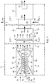
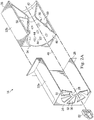
- a specially designed combustion system 10 of a fuel-fired heating appliance is schematically depicted in FIG. 1 and includes, from left to right as viewed in FIG. 1 , a primary fuel/air mixing structure 14, a secondary fuel/air mixing structure 16, and a fuel/air mixture combustion structure 18 to which a plurality of heat exchanger tubes 20 (representatively five in number) are operatively connected as later described herein.
- the primary fuel/air mixing structure 14 disposed at the left end of the combustion system 10 embodies principles of the present invention and comprises a rectangular housing structure 22 having an outer portion 22a and an inner portion 22b telescoped into the outer portion 22a as may be seen in FIGS. 2 and 2A .
- Outer housing portion 22a has an inlet end wall 24 and an open outlet end 26.
- a central circular opening 28 is formed in the inlet end wall 24 and is circumscribed by an annular end wall opening 30 radially across which an circumferentially spaced array of swirl-inducing vanes 32 radially extends.
- Inner housing portion 22b has open inlet and outlet ends 34,36 and laterally circumscribes a venturi structure 38 having enlarged open inlet and outlet end portions 40 and 42.
- Venturi structure 38 has perforations 44 formed in its sidewall. Representatively, the perforations 44 are formed only in the inlet end portion 40 of the venturi structure 38, but could be located on additional or other portions of the venturi structure sidewall if desired. As shown in FIGS. 1 and 2A , a longitudinal axis 46 extends centrally through the interior of the venturi structure 38. With the inner housing portion 22b telescoped into the outer housing portion 22a, the axis 46 extends centrally through the central housing wall opening 28, and the outlet ends 26,36 of the housing portions 22a,22b combinatively define an open outlet end 48 of the overall primary fuel/air mixing structure 14.
- the inner housing portion 22b defines a sound-attenuating chamber 50 that laterally circumscribes the venturi structure 38 and communicates with its interior via the venturi sidewall perforations 44.
- a radial fuel injector 52 is operatively received in the central housing wall opening 28, and projects axially into the open inlet end portion 40 of the venturi structure 38 for purposes later described herein.
- the secondary fuel/air mixing structure 16 comprises a secondary mixing housing 54 having an open inlet end 56 coupled to the open inlet end 48 of the housing 22, and an open outlet end 58 coupled to the open inlet end 60 of a burner box housing portion 62 of the fuel/air mixture combustion structure 18.
- a specially designed perforated diffuser plate 64 embodying principles of the present invention and uniquely functioning in a manner later described herein.
- the housing 62 has a closed right end wall 66 spaced apart from and facing the perforated diffuser plate 64.
- an igniter 68 Positioned between the diffuser plate 64 and the end wall 66 is an igniter 68 operative to ignite a fuel/air mixture entering the housing 62 as later described herein.
- the previously mentioned heat exchanger tubes 20 form with the fuel/air mixture combustion structure 18 a heat transfer structure portion of the furnace 12 and have, as viewed in FIG. 1 , left inlet end portions coupled to the housing 62 end wall 66 and communicating with the interior of the housing 62. As viewed in FIG. 1 , right outlet ends of the heat exchanger tubes 20 are communicated with the interior of a collector box structure 70 within which a draft inducer fan 72 is operatively disposed.
- the draft inducer fan 72 draws combustion air 74 into the open inlet end portion 40 of the venturi structure 38, across the vanes 32, and then rightwardly through the interior of the venturi structure 38. Vanes 32 cause the combustion air 74 to internally traverse the venturi structure 38 in a swirling pattern 74a generally centered about the venturi structure longitudinal axis 46.
- the fuel injector 52 receives gaseous fuel via a fuel supply line 76 and responsively discharges gaseous fuel jets 78 radially outwardly into the swirling combustion air 74a.
- the gaseous fuel in the jets 78 mixes with the swirling combustion air 74a to form therewith a fuel/air mixture 80 that enters the secondary mixing housing 54 and is further mixed therein.
- the fuel/air mixture 80 within the secondary mixing housing 54 is then drawn through the perforated diffuser plate 64 into the interior of the burner box housing portion 62 wherein the igniter 68 combusts the fuel/air mixture 80 to form therefrom hot combustion gas 82 that is flowed rightwardly through the heat exchanger tubes 20.
- a supply air fan portion of the furnace 12 flows air 84 to be heated externally across the heat exchanger tubes 20 to receive combustion heat therefrom and create a flow of heated air 84a for delivery to a conditioned space served by the furnace 12.
- Combustion heat transfer from the heat exchanger tubes 20 to the air 84 causes the tube-entering hot combustion gas 82 to rightwardly exit the heat exchanger tubes 20 as cooled combustion gas 82a that enters the collector box 70 and is expelled therefrom, by the draft inducer fan 72, to a suitable flue structure (not shown).
- the venturi-based primary fuel/air mixing structure 14 provides several advantages. For example, due to the cross-flow injection technique utilizing the combustion air 74a swirling through the venturi interior in combination with the radially directed interior fuel jets 78, an improved degree of fuel/air mixing is achieved within the venturi structure 38. This enhanced degree of fuel/air mixing is further increased by the use of the secondary fuel/air mixing structure 16 which serves to further mix the fuel and air by providing further "residence" time for the fuel/air mixture created in the venturi structure 38 before it enters the fuel/air mixture burner box housing 62 for combustion therein.
- the construction of the primary fuel/air mixing structure 14 substantially reduces the fuel/air mixing noise during both start-up and steady state operation of the furnace 12.
- the perforations 44 in the sidewall of the venturi structure 38 permit the fuel/air mixture traversing it to enter and fill the chamber 50 circumscribing the venturi structure 38. This creates within the chamber 50 a fluid damping volume that absorbs and damps noise-creating fluid pressure oscillations in the venturi interior, thereby desirably lessening the operational sound level of the primary fuel/air mixing structure 14.
- the enhanced mixing of the fuel/air mixture to be combusted desirably reduces the level of NOx emissions created by the furnace 12 during firing thereof.
- the draft inducer fan 72 is representatively centered in a left-to-right direction within the collector box 70 and with respect to the five illustratively depicted heat exchanger tubes 20. Accordingly, the suction force of the fan 72 is similarly centered relative to the array of heat exchanger tubes 20. Without the incorporation in the furnace 12 of a subsequently described feature of the present invention, the result would be that the per-tube flow of hot combustion gas 82 is greater for the central tubes 20b than it is for the end tubes 22a. In turn, this would create an undesirable non-uniform temperature distribution across the heat exchanger tube array, with the central tubes 20b having higher operating temperatures than those of the end tubes 20a.
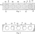
- the previously mentioned diffuser plate 64 installed at the juncture between the secondary fuel/air mixing housing 54 and the burner box housing 62 representatively has an elongated rectangular shape, and is substantially aligned with the open inlet ends of the heat exchanger tubes 20.
- a series of relatively small perforations 86 along substantially the entire length of the diffuser plate 64 are formed a series of relatively small perforations 86 (see FIG. 3 ), with relatively larger perforations 88 being additionally formed through the opposite end portions of the diffuser plate 64.
- This perforation pattern provides opposite end portions of the diffuser plate 64 (which are generally aligned with the inlets of the end heat exchanger tubes 20a) with greater fuel/air mixture through-flow areas than the diffuser plate fuel/air mixture through-flow areas aligned with the inlets of the central heat exchanger tubes 20b.
- the presence of the diffuser plate 64 lessens the flow of hot combustion gas 82 through the central heat exchanger tubes 20b and increases the flow of hot combustion gas 82 through the end heat exchanger tubes 20a, with the perforation pattern in the diffuser plate 64 functioning to substantially alleviate non-uniform temperature distribution across the heat exchanger tube array that might otherwise occur.
- principles of the present invention provide a simple and quite inexpensive solution to the potential problem of non-uniform temperature distribution across the heat exchanger tube array.
- non-uniformly perforated diffuser plate 64 also provides for further mixing of the fuel/air mixture 80 entering the burner box housing 62, thereby providing an additional beneficial reduction in the NOx level of the discharged combustion gas 82a.
- the diffuser plate hole pattern could have a different overall configuration operative to alter in a predetermined, different manner the relative combustion gas flow rates through selected ones of the heat exchanger tubes 20.
Landscapes
- Engineering & Computer Science (AREA)
- Chemical & Material Sciences (AREA)
- Combustion & Propulsion (AREA)
- Mechanical Engineering (AREA)
- General Engineering & Computer Science (AREA)
- Physics & Mathematics (AREA)
- Thermal Sciences (AREA)
- Gas Burners (AREA)
Claims (8)
- Appareil de chauffage à combustible comprenant :
un système de combustion (10) comportant :un carter de brûleur (62) couplé à une structure de mélange combustible-air (14) configurée pour générer un mélange combustible-air (80), le carter de brûleur (62) présentant un intérieur, une extrémité d'entrée (60), et une extrémité de sortie (66) ;un dispositif d'allumage (68) disposé dans l'intérieur du carter de brûleur (62) entre l'extrémité d'entrée (60) et l'extrémité de sortie et servant à brûler le mélange combustible-air (80) qui entre dans l'intérieur du carter de brûleur (62) depuis la structure de mélange combustible-air (14) par l'extrémité d'entrée (60) du carter de brûleur (62) afin de former un gaz de combustion chaud (82) dans l'intérieur du carter de brûleur (62) ;un réseau de tubes échangeurs de chaleur (20) présentant des entrées communiquant avec l'intérieur du carter de brûleur (62) par le biais de l'extrémité de sortie du carter de brûleur (62) destinées à recevoir le gaz de combustion chaud (82) généré dans l'intérieur du carter de brûleur (62), les sorties des tubes échangeurs de chaleur étant couplées à une boîte collectrice (70) ;un ventilateur (72) servant à induire un flux du gaz de combustion chaud (82) depuis l'intérieur du carter de brûleur (62) à travers le réseau de tubes échangeurs de chaleur (20) de telle sorte qu'un flux par tube échangeur de chaleur du gaz de combustion chaud (82) d'un premier ensemble de tubes échangeurs de chaleur (20b) soit supérieur à celui d'un second ensemble de tubes échangeurs de chaleur (20a) créant une répartition de température non uniforme dans le réseau de tubes échangeurs de chaleur (20) durant le fonctionnement de l'appareil de chauffage à combustible ; dans lequelun appareil diffuseur (64) comprenant une pluralité de perforations non uniformes qui comprennent : (a) un premier ensemble de perforations (86) disposé à travers tout l'appareil diffuseur allongé (64), et (b) un second ensemble de perforations (88) qui sont d'une taille supérieure à celles du premier ensemble de perforations (86), le second ensemble de perforations (88) étant disposé au niveau d'une partie de l'appareil diffuseur allongé (64) de telle sorte que la partie de l'appareil diffuseur allongée comprenne à la fois le premier ensemble de perforations (86) et le second ensemble de perforations (88),dans lequel l'appareil diffuseur allongé (64) est disposé à l'extrémité d'entrée (60) du carter de brûleur (62) et agencé de telle sorte que le premier ensemble de perforations (86) fasse face aux premier et second ensembles de tubes échangeurs de chaleur (20a, 20b) tandis que la partie de l'appareil diffuseur allongé (64) comprenant les premier et second ensembles de perforations (86, 88) fait face au second ensemble de tubes échangeurs de chaleur (20a), etdans lequel ledit agencement de l'appareil diffuseur allongé (64) à l'extrémité d'entrée (60) du carter de brûleur (62) est configuré pou modifier des débits d'écoulement de gaz de combustion relatifs à travers le premier ensemble de tubes échangeurs de chaleur (20b) et le second ensemble de tubes échangeurs de chaleur (20a) d'une manière qui réduit la répartition de température non uniforme entre le premier ensemble de tubes échangeurs de chaleur (20b) et le second ensemble de tubes échangeurs de chaleur (20a) en laissant passer un plus grand volume du mélange combustible-air (80) à travers la partie de l'appareil diffuseur allongé (64) faisant face au second ensemble de tubes échangeurs de chaleur (20a) par rapport à une partie restante de l'appareil diffuseur allongé (64). - Appareil de chauffage à combustible selon la revendication 1 dans lequel : l'appareil de chauffage à combustible est un four de chauffage à air à combustible.
- Appareil de chauffage à combustible selon la revendication 1 dans lequel : l'appareil diffuseur est une plaque de diffusion.
- Appareil de chauffage à combustible selon la revendication 1 dans lequel la structure de mélange combustible-air (14) du système de combustion comporte :un logement (22) présentant une seconde extrémité d'entrée (24), et une seconde extrémité de sortie (26) couplée à l'extrémité d'entrée (60) du carter de brûleur (62),une structure de Venturi (38) disposée dans le logement (22), la structure de Venturi (38) entourant un axe (46) s'étendant entre les secondes extrémités d'entrée (24) et de sortie (26) du logement (22) et comprenant : (a) une entrée de Venturi (40) adjacente à la seconde extrémité d'entrée (24) du logement (22), (b) une sortie de Venturi (42) adjacente à la seconde extrémité de sortie (26) du logement (22), et (c) une paroi latérale s'étendant depuis l'entrée de Venturi (40) jusqu'à la sortie de Venturi (42) de telle sorte que la paroi latérale présente un amincissement depuis l'entrée de Venturi (40) et la sortie de Venturi (42) vers une partie sensiblement centrale de la structure de Venturi (38),dans lequel la paroi latérale de la structure de Venturi (38) comprend une pluralité de perforations (44) qui sont disposées sensiblement autour de la paroi latérale depuis une position adjacente à l'entrée de Venturi (40) jusqu'à la partie sensiblement centrale de la structure de Venturi (38),une structure d'aubes (32) associée à la seconde extrémité d'entrée (24) du logement (22) et servant à conférer à l'air de combustion entrant dans l'entrée de Venturi (40), et traversant l'intérieur de la structure de Venturi (38), par fonctionnement du ventilateur (72), une configuration de flux tourbillonnant autour de l'axe (46), etun injecteur de combustible (52) servant à injecter radialement un combustible depuis une source de combustible dans l'air de combustion tourbillonnant qui traverse l'intérieur de la structure de Venturi (38) pour former avec l'air de combustion tourbillonnant le mélange combustible-air (80) poussant s'écouler dans l'intérieur du carter de brûleur (62) à travers l'appareil diffuseur allongé (64).
- Appareil de chauffage à combustible selon la revendication 4 dans lequel :
le logement (22) définit en son sein une chambre (50) qui s'étend latéralement autour de la structure de Venturi (38) et communique avec l'intérieur de la structure de Venturi (38) par l'intermédiaire de la pluralité de perforations (44) sur la paroi latérale de la structure de Venturi de telle sorte que le mélange combustible-air (80) traversant la pluralité de perforations (44) entre dans la chambre et la remplisse pour créer un volume d'atténuation de bruit et atténuer les fluctuations de pression au sein de la structure de Venturi, diminuant ainsi un bruit de mélange combustible-air durant le fonctionnement de l'appareil de chauffage à combustible. - Appareil de chauffage à combustible selon la revendication 5 dans lequel :
le logement comporte une partie de logement externe et une partie de logement interne entrant à la manière d'un télescope dans la partie de logement externe, l'injecteur de combustible et la structure d'aubes étant portés sur la partie de logement externe, et la partie de logement interne portant intérieurement la structure de Venturi et définissant la chambre. - Appareil de chauffage à combustible selon la revendication 5 dans lequel le système de combustion comporte en outre :
un second logement (16) interposé entre des intérieurs du logement (14) et du carter de brûleur (62) et communiquant avec ceux-ci et servant à mélanger davantage les combustible et air déchargés du logement. - Procédé de transfert de chaleur de combustion à un fluide, le procédé comprenant les étapes suivantes :la fourniture d'un logement (62) couplé à une structure de mélange combustible-air (14) configurée pour générer un mélange combustible-air (80), le logement (62) présentant une paroi (66) dans une relation face à face espacée avec une partie d'entrée (60) à travers laquelle le mélange combustible-air (80) peut s'écouler pour entrer dans un intérieur du logement (62) ;le raccordement à la paroi (66), d'extrémités d'entrée d'une pluralité de tubes échangeurs de chaleur (20), dans lequel la pluralité de tubes échangeurs de chaleur (20) comprend un premier ensemble de tubes échangeurs de chaleur (20b) et un second ensemble de tubes échangeurs de chaleur (20a) qui sont agencés de telle sorte qu'un ventilateur (72) aspire un plus grand volume de gaz de combustion chaud (82) à travers le premier ensemble de tubes échangeurs de chaleur (20b) qu'à travers le second ensemble de tubes échangeurs de chaleur (20a) durant le fonctionnement d'un four de chauffage à combustible créant ainsi une répartition de température non uniforme à travers la pluralité de tubes échangeurs de chaleur (20) ;l'écoulement du mélange combustible-air (80) dans l'intérieur du logement (62) à travers une structure de diffuseur allongé (64) disposée au niveau de la partie d'entrée (60) du logement (62), la structure de diffuseur allongé (64) présentant une pluralité de perforations non uniformes qui comprennent : (a) un premier ensemble de perforations (86) disposé à travers toute la structure de diffuseur allongé (64), et (b) un second ensemble de perforations (88) d'une taille supérieure à celles du premier ensemble de perforations (86), le second ensemble de perforations (88) étant disposé au niveau d'une partie de la structure de diffuseur allongé (64) de telle sorte que la partie de la structure de diffuseur allongé comprenne à la fois le premier ensemble de perforations (86) et le second ensemble de perforations (88),
dans lequel la structure de diffuseur allongé (64) est agencée de telle sorte que le premier ensemble de perforations (88) fasse face aux premier et second ensembles de tubes échangeurs de chaleur (20a, 20b) tandis que la partie de la structure de diffuseur allongé (64) comprenant les premier et second ensembles de perforations (86, 88) fait face au second ensemble de tubes échangeurs de chaleur (20a) ;l'allumage du mélange combustible-air (80) pour former dans le logement (62) le gaz de combustion chaud (82) qui s'écoule vers l'extérieur vers le premier ensemble de tubes échangeurs de chaleur (20b) et le second ensemble de tubes échangeurs de chaleur (20a) ; etl'écoulement d'un fluide à chauffer à travers le premier ensemble de tubes échangeurs de chaleur (20b) et le second ensemble de tubes échangeurs de chaleur (20a) pour transférer la chaleur de combustion du premier ensemble de tubes échangeurs de chaleur (20b) et du second ensemble de tubes échangeurs de chaleur (20a) au fluide,
dans lequel l'agencement de la structure de diffuseur allongé (64) au niveau de la partie d'entrée (60) du logement (62) est configuré pour sensiblement modifier des débits d'écoulement de gaz de combustion relatifs à travers le premier ensemble de tubes échangeurs de chaleur (20b) et le second ensemble de tubes échangeurs de chaleur (20a) d'une manière prédéterminée qui réduit la répartition de température non uniforme entre le premier ensemble de tubes échangeurs de chaleur (20b) et le second ensemble de tubes échangeurs de chaleur (20a) en laissant passer un plus grand volume du mélange combustible-air (80) dans l'intérieur du logement (62) à travers la partie de la structure de diffuseur allongé (64) faisant face au second ensemble de tubes échangeurs de chaleur (20a) par rapport à une partie restante de la structure de diffuseur allongé (64).
Priority Applications (1)
| Application Number | Priority Date | Filing Date | Title |
|---|---|---|---|
| EP19171776.8A EP3561383A1 (fr) | 2013-09-26 | 2014-09-12 | Mélange air/carburant et appareil de combustion |
Applications Claiming Priority (4)
| Application Number | Priority Date | Filing Date | Title |
|---|---|---|---|
| US201361883031P | 2013-09-26 | 2013-09-26 | |
| US14/084,095 US9739483B2 (en) | 2013-09-26 | 2013-11-19 | Fuel/air mixture and combustion apparatus and associated methods for use in a fuel-fired heating apparatus |
| US14/337,625 US9951945B2 (en) | 2013-09-26 | 2014-07-22 | Diffuser plate for premixed burner box |
| PCT/US2014/055381 WO2015047748A1 (fr) | 2013-09-26 | 2014-09-12 | Mélange air/carburant et appareil de combustion |
Related Child Applications (2)
| Application Number | Title | Priority Date | Filing Date |
|---|---|---|---|
| EP19171776.8A Division-Into EP3561383A1 (fr) | 2013-09-26 | 2014-09-12 | Mélange air/carburant et appareil de combustion |
| EP19171776.8A Division EP3561383A1 (fr) | 2013-09-26 | 2014-09-12 | Mélange air/carburant et appareil de combustion |
Publications (3)
| Publication Number | Publication Date |
|---|---|
| EP3049723A1 EP3049723A1 (fr) | 2016-08-03 |
| EP3049723A4 EP3049723A4 (fr) | 2017-06-07 |
| EP3049723B1 true EP3049723B1 (fr) | 2019-06-12 |
Family
ID=52689844
Family Applications (2)
| Application Number | Title | Priority Date | Filing Date |
|---|---|---|---|
| EP14847622.9A Not-in-force EP3049723B1 (fr) | 2013-09-26 | 2014-09-12 | Mélange air/carburant et appareil de combustion |
| EP19171776.8A Withdrawn EP3561383A1 (fr) | 2013-09-26 | 2014-09-12 | Mélange air/carburant et appareil de combustion |
Family Applications After (1)
| Application Number | Title | Priority Date | Filing Date |
|---|---|---|---|
| EP19171776.8A Withdrawn EP3561383A1 (fr) | 2013-09-26 | 2014-09-12 | Mélange air/carburant et appareil de combustion |
Country Status (7)
| Country | Link |
|---|---|
| US (6) | US9739483B2 (fr) |
| EP (2) | EP3049723B1 (fr) |
| CN (2) | CN105745495B (fr) |
| AU (2) | AU2014328025B2 (fr) |
| CA (2) | CA3010826C (fr) |
| MX (1) | MX373891B (fr) |
| WO (1) | WO2015047748A1 (fr) |
Families Citing this family (22)
| Publication number | Priority date | Publication date | Assignee | Title |
|---|---|---|---|---|
| US9739483B2 (en) | 2013-09-26 | 2017-08-22 | Rheem Manufacturing Company | Fuel/air mixture and combustion apparatus and associated methods for use in a fuel-fired heating apparatus |
| EP3018408B1 (fr) * | 2014-11-05 | 2017-06-07 | WORGAS BRUCIATORI S.r.l. | Brûleur |
| US10767900B2 (en) | 2015-05-14 | 2020-09-08 | Lochinvar, Llc | Burner with flow distribution member |
| US10281144B2 (en) * | 2015-10-15 | 2019-05-07 | Weber-Stephen Products Llc | Gas inlet fixture and air shutter |
| CN110274225B (zh) * | 2017-05-22 | 2020-10-30 | 中国北方车辆研究所 | 一种安装支架及其燃烧器系统 |
| US10619656B1 (en) * | 2017-05-31 | 2020-04-14 | Daniel A. Handley | Fluid turbulence inducement apparatus and system |
| US10711997B2 (en) * | 2017-10-03 | 2020-07-14 | Lennox Industries Inc. | Burner box liner for low NOx emission furnace |
| US10711998B2 (en) | 2017-10-03 | 2020-07-14 | Lennox Industries Inc. | Fresh air intake for low NOx emission furnace |
| US11187433B2 (en) | 2017-10-03 | 2021-11-30 | Lennox Industries Inc. | Pre-mix burner assembly for low NOx emission furnace |
| US11060480B2 (en) * | 2017-11-14 | 2021-07-13 | The Boeing Company | Sound-attenuating heat exchangers and methods of utilizing the same |
| US10451271B2 (en) * | 2017-12-20 | 2019-10-22 | Honeywell International Inc. | Staged fuel burner with jet induced exhaust gas recycle |
| WO2019246600A1 (fr) * | 2018-06-22 | 2019-12-26 | Goodman Manufacturing Company, L.P. | Système et procédé de chauffage |
| US11953200B2 (en) | 2018-09-27 | 2024-04-09 | Carrier Corporation | Burner assembly having a baffle |
| US11143170B2 (en) | 2019-06-28 | 2021-10-12 | The Boeing Company | Shape memory alloy lifting tubes and shape memory alloy actuators including the same |
| US11168584B2 (en) | 2019-06-28 | 2021-11-09 | The Boeing Company | Thermal management system using shape memory alloy actuator |
| US11525438B2 (en) | 2019-06-28 | 2022-12-13 | The Boeing Company | Shape memory alloy actuators and thermal management systems including the same |
| US11499747B2 (en) * | 2019-10-04 | 2022-11-15 | Rheem Manufacturing Company | Heat exchanger tubes and tube assembly configurations |
| CN111121022B (zh) * | 2019-12-31 | 2021-08-24 | 西安交通大学 | 一种基于热管换热的低氮燃气燃烧器 |
| CN111649324B (zh) * | 2020-06-12 | 2023-01-13 | 烟台龙源电力技术股份有限公司 | 燃烧器和锅炉 |
| US11819811B2 (en) * | 2020-06-23 | 2023-11-21 | Noritz Corporation | Premixing device and combustion device equipped with the premixing device |
| CN111777341B (zh) * | 2020-07-03 | 2021-11-19 | 中琉科技有限公司 | 一种石灰石悬浮煅烧设备 |
| CN119661096B (zh) * | 2024-12-02 | 2026-03-17 | 中国建筑材料科学研究总院有限公司 | 气体分散加热装置和连续化制备碳纳米管原位改性玻璃纤维的设备及方法 |
Family Cites Families (37)
| Publication number | Priority date | Publication date | Assignee | Title |
|---|---|---|---|---|
| US388018A (en) | 1888-08-21 | William m | ||
| US1902970A (en) * | 1929-11-16 | 1933-03-28 | Gen Motors Res Corp | Oil cooler |
| US2249271A (en) | 1938-11-28 | 1941-07-15 | Curtiss L Davis | Aircraft engine exhaust silencer and back pressure reducer |
| US3181646A (en) | 1963-04-15 | 1965-05-04 | Howard C Edwards | Silencer having contiguous concentric layers of sound absorbent material |
| AT297996B (de) | 1970-09-14 | 1972-04-25 | Vaillant Joh Kg | Brennerplatte, insbesondere für Ölgas- oder Gas-Gebläsebrenner |
| US3888018A (en) * | 1974-05-10 | 1975-06-10 | Degraff Products Company | Hair dryer |
| US4224019A (en) * | 1978-02-27 | 1980-09-23 | Westinghouse Electric Corp. | Power burner for compact furnace |
| US4690245A (en) * | 1983-03-17 | 1987-09-01 | Stemco, Inc. | Flattened venturi, method and apparatus for making |
| US4773384A (en) * | 1983-11-04 | 1988-09-27 | Modern Home Products Corp. | Adjustable gas intake assembly |
| US4762530A (en) * | 1986-01-28 | 1988-08-09 | Modern Home Products Corp. | Internal air shutter for gas burner |
| US4805587A (en) * | 1988-03-18 | 1989-02-21 | Universal Enterprises, Inc. | Gas grill |
| JPH03284518A (ja) | 1989-11-16 | 1991-12-16 | Santetsukusu:Kk | メダルリフタ |
| US5198625A (en) * | 1991-03-25 | 1993-03-30 | Alexander Borla | Exhaust muffler for internal combustion engines |
| US5127824A (en) * | 1991-07-03 | 1992-07-07 | Barbecue Innovations Incorporated | Barbecue burner |
| US5240411A (en) | 1992-02-10 | 1993-08-31 | Mor-Flo Industries, Inc. | Atmospheric gas burner assembly |
| US5274995A (en) | 1992-04-27 | 1994-01-04 | General Electric Company | Apparatus and method for atomizing water in a combustor dome assembly |
| CN1085304A (zh) * | 1992-09-30 | 1994-04-13 | 富良 | 双斜面火管燃烧器 |
| US5291875A (en) * | 1992-10-16 | 1994-03-08 | Modern Home Products Corp. | Adjustable tube assembly for a gas barbecue grill |
| JP3284518B2 (ja) * | 1993-02-26 | 2002-05-20 | 株式会社ノーリツ | 燃焼装置 |
| US5460512A (en) | 1993-05-27 | 1995-10-24 | Coen Company, Inc. | Vibration-resistant low NOx burner |
| US5546925A (en) | 1995-08-09 | 1996-08-20 | Rheem Manufacturing Company | Inshot fuel burner Nox reduction device with integral positioning support structure |
| US5791137A (en) | 1995-11-13 | 1998-08-11 | United Technologies Corporation | Radial inflow dual fuel injector |
| US6022213A (en) | 1997-07-01 | 2000-02-08 | Paper Machinery Corporation | Gas fired heater |
| US6721644B2 (en) | 2000-08-02 | 2004-04-13 | Alfred B. Levine | Vehicle drive override subsystem |
| US6857870B2 (en) * | 2001-05-09 | 2005-02-22 | Topp Construction Services, Inc. | Combustion system for a heater |
| US6786717B2 (en) * | 2002-01-24 | 2004-09-07 | Noritz Corporation | Combustion apparatus |
| KR100830316B1 (ko) * | 2002-08-09 | 2008-05-19 | 제이에프이 스틸 가부시키가이샤 | 관상화염버너, 그 연소제어방법 및 장치 |
| KR100551522B1 (ko) * | 2002-12-11 | 2006-02-13 | 파이오니아 가부시키가이샤 | 플라즈마 디스플레이 패널의 소성로 및 플라즈마디스플레이 패널의 제조 방법 |
| US6880548B2 (en) * | 2003-06-12 | 2005-04-19 | Honeywell International Inc. | Warm air furnace with premix burner |
| FR2899956B1 (fr) * | 2006-04-14 | 2008-07-25 | Thirode Grandes Cuisines Poligny | Bruleur a gaz pour four de cuisine |
| KR100883796B1 (ko) * | 2008-01-16 | 2009-02-19 | 주식회사 경동나비엔 | 린-리치 연소방식을 이용한 분젠버너 |
| US8591222B2 (en) | 2009-10-30 | 2013-11-26 | Trane International, Inc. | Gas-fired furnace with cavity burners |
| US8545213B2 (en) * | 2010-03-09 | 2013-10-01 | Air Products And Chemicals, Inc. | Reformer and method of operating the reformer |
| US8919337B2 (en) * | 2012-02-17 | 2014-12-30 | Honeywell International Inc. | Furnace premix burner |
| US9032940B2 (en) | 2013-01-18 | 2015-05-19 | Cummins Inc. | Systems and methods for dedicated exhaust gas recirculation and control |
| US8985999B2 (en) * | 2013-01-18 | 2015-03-24 | Trane International Inc. | Fuel/air furnace mixer |
| US9739483B2 (en) * | 2013-09-26 | 2017-08-22 | Rheem Manufacturing Company | Fuel/air mixture and combustion apparatus and associated methods for use in a fuel-fired heating apparatus |
-
2013
- 2013-11-19 US US14/084,095 patent/US9739483B2/en active Active
-
2014
- 2014-07-22 US US14/337,625 patent/US9951945B2/en active Active
- 2014-09-12 AU AU2014328025A patent/AU2014328025B2/en not_active Ceased
- 2014-09-12 EP EP14847622.9A patent/EP3049723B1/fr not_active Not-in-force
- 2014-09-12 WO PCT/US2014/055381 patent/WO2015047748A1/fr not_active Ceased
- 2014-09-12 EP EP19171776.8A patent/EP3561383A1/fr not_active Withdrawn
- 2014-09-12 CA CA3010826A patent/CA3010826C/fr active Active
- 2014-09-12 MX MX2016003649A patent/MX373891B/es active IP Right Grant
- 2014-09-12 CN CN201480052881.XA patent/CN105745495B/zh not_active Expired - Fee Related
- 2014-09-12 CN CN201910965549.7A patent/CN110617479B/zh not_active Expired - Fee Related
- 2014-09-12 CA CA2924810A patent/CA2924810C/fr active Active
-
2017
- 2017-07-13 US US15/649,454 patent/US10571122B2/en active Active
- 2017-11-07 AU AU2017258832A patent/AU2017258832B2/en not_active Ceased
-
2018
- 2018-03-26 US US15/935,974 patent/US10976048B2/en active Active
-
2020
- 2020-02-24 US US16/799,265 patent/US11402093B2/en active Active
-
2022
- 2022-07-29 US US17/877,493 patent/US12366357B2/en active Active
Non-Patent Citations (1)
| Title |
|---|
| None * |
Also Published As
| Publication number | Publication date |
|---|---|
| MX373891B (es) | 2020-07-09 |
| US20150083105A1 (en) | 2015-03-26 |
| US20180216817A1 (en) | 2018-08-02 |
| CA3010826C (fr) | 2021-06-01 |
| CN110617479B (zh) | 2022-02-08 |
| US10571122B2 (en) | 2020-02-25 |
| CA2924810A1 (fr) | 2015-04-02 |
| US20170328561A1 (en) | 2017-11-16 |
| US20220381432A1 (en) | 2022-12-01 |
| US10976048B2 (en) | 2021-04-13 |
| US11402093B2 (en) | 2022-08-02 |
| EP3049723A4 (fr) | 2017-06-07 |
| AU2014328025A1 (en) | 2016-04-07 |
| AU2014328025B2 (en) | 2017-08-31 |
| AU2017258832A1 (en) | 2017-11-23 |
| WO2015047748A1 (fr) | 2015-04-02 |
| US20200191388A1 (en) | 2020-06-18 |
| MX2016003649A (es) | 2016-06-24 |
| CN105745495B (zh) | 2019-11-05 |
| US12366357B2 (en) | 2025-07-22 |
| EP3049723A1 (fr) | 2016-08-03 |
| US9739483B2 (en) | 2017-08-22 |
| CN110617479A (zh) | 2019-12-27 |
| CA3010826A1 (fr) | 2015-04-02 |
| EP3561383A1 (fr) | 2019-10-30 |
| CN105745495A (zh) | 2016-07-06 |
| AU2017258832B2 (en) | 2019-06-13 |
| US9951945B2 (en) | 2018-04-24 |
| US20150086934A1 (en) | 2015-03-26 |
| CA2924810C (fr) | 2018-08-21 |
Similar Documents
| Publication | Publication Date | Title |
|---|---|---|
| US12366357B2 (en) | Fuel/air mixture and combustion apparatus and associated methods for use in a fuel-fired heating apparatus | |
| CN105934638B (zh) | 用于多管换热器的多锥体燃料燃烧器设备 | |
| US8985999B2 (en) | Fuel/air furnace mixer | |
| US20150369495A1 (en) | ULTRA-LOW NOx BURNER | |
| CA2718589C (fr) | Generateur d'air chaud a gaz avec bruleurs a cavites preformes alimentesaxialement et radialementt | |
| CN102084182A (zh) | 低NOx燃烧器 | |
| JP2016029316A (ja) | 給湯装置 | |
| US6059566A (en) | Burner apparatus | |
| US20160178236A1 (en) | Inward fired pre-mix burners with carryover | |
| CN109556110A (zh) | 用于产生热水或蒸汽的锅炉 | |
| JP5160139B2 (ja) | 給湯器用バーナ | |
| CN102057221B (zh) | 气体火焰稳定方法及设备 | |
| US20240310039A1 (en) | Gas furnace with heat exchanger | |
| EP3865770A2 (fr) | Brûleur à très faible nox | |
| WO2025049460A1 (fr) | Four à gaz doté d'une plaque de protection thermique | |
| CN120212501A (zh) | 风道混气结构及燃气热水设备 |
Legal Events
| Date | Code | Title | Description |
|---|---|---|---|
| PUAI | Public reference made under article 153(3) epc to a published international application that has entered the european phase |
Free format text: ORIGINAL CODE: 0009012 |
|
| 17P | Request for examination filed |
Effective date: 20160323 |
|
| AK | Designated contracting states |
Kind code of ref document: A1 Designated state(s): AL AT BE BG CH CY CZ DE DK EE ES FI FR GB GR HR HU IE IS IT LI LT LU LV MC MK MT NL NO PL PT RO RS SE SI SK SM TR |
|
| AX | Request for extension of the european patent |
Extension state: BA ME |
|
| DAX | Request for extension of the european patent (deleted) | ||
| A4 | Supplementary search report drawn up and despatched |
Effective date: 20170508 |
|
| RIC1 | Information provided on ipc code assigned before grant |
Ipc: F24H 3/00 20060101ALI20170428BHEP Ipc: F23D 14/70 20060101ALI20170428BHEP Ipc: F23D 14/08 20060101ALI20170428BHEP Ipc: F23D 14/46 20060101AFI20170428BHEP |
|
| GRAP | Despatch of communication of intention to grant a patent |
Free format text: ORIGINAL CODE: EPIDOSNIGR1 |
|
| STAA | Information on the status of an ep patent application or granted ep patent |
Free format text: STATUS: GRANT OF PATENT IS INTENDED |
|
| INTG | Intention to grant announced |
Effective date: 20180921 |
|
| GRAJ | Information related to disapproval of communication of intention to grant by the applicant or resumption of examination proceedings by the epo deleted |
Free format text: ORIGINAL CODE: EPIDOSDIGR1 |
|
| STAA | Information on the status of an ep patent application or granted ep patent |
Free format text: STATUS: REQUEST FOR EXAMINATION WAS MADE |
|
| GRAS | Grant fee paid |
Free format text: ORIGINAL CODE: EPIDOSNIGR3 |
|
| STAA | Information on the status of an ep patent application or granted ep patent |
Free format text: STATUS: GRANT OF PATENT IS INTENDED |
|
| GRAP | Despatch of communication of intention to grant a patent |
Free format text: ORIGINAL CODE: EPIDOSNIGR1 |
|
| INTC | Intention to grant announced (deleted) | ||
| INTG | Intention to grant announced |
Effective date: 20190214 |
|
| GRAA | (expected) grant |
Free format text: ORIGINAL CODE: 0009210 |
|
| STAA | Information on the status of an ep patent application or granted ep patent |
Free format text: STATUS: THE PATENT HAS BEEN GRANTED |
|
| AK | Designated contracting states |
Kind code of ref document: B1 Designated state(s): AL AT BE BG CH CY CZ DE DK EE ES FI FR GB GR HR HU IE IS IT LI LT LU LV MC MK MT NL NO PL PT RO RS SE SI SK SM TR |
|
| REG | Reference to a national code |
Ref country code: GB Ref legal event code: FG4D |
|
| REG | Reference to a national code |
Ref country code: CH Ref legal event code: EP |
|
| REG | Reference to a national code |
Ref country code: AT Ref legal event code: REF Ref document number: 1143035 Country of ref document: AT Kind code of ref document: T Effective date: 20190615 |
|
| REG | Reference to a national code |
Ref country code: DE Ref legal event code: R096 Ref document number: 602014048366 Country of ref document: DE |
|
| REG | Reference to a national code |
Ref country code: IE Ref legal event code: FG4D |
|
| REG | Reference to a national code |
Ref country code: NL Ref legal event code: MP Effective date: 20190612 |
|
| REG | Reference to a national code |
Ref country code: LT Ref legal event code: MG4D |
|
| PG25 | Lapsed in a contracting state [announced via postgrant information from national office to epo] |
Ref country code: NO Free format text: LAPSE BECAUSE OF FAILURE TO SUBMIT A TRANSLATION OF THE DESCRIPTION OR TO PAY THE FEE WITHIN THE PRESCRIBED TIME-LIMIT Effective date: 20190912 Ref country code: AL Free format text: LAPSE BECAUSE OF FAILURE TO SUBMIT A TRANSLATION OF THE DESCRIPTION OR TO PAY THE FEE WITHIN THE PRESCRIBED TIME-LIMIT Effective date: 20190612 Ref country code: SE Free format text: LAPSE BECAUSE OF FAILURE TO SUBMIT A TRANSLATION OF THE DESCRIPTION OR TO PAY THE FEE WITHIN THE PRESCRIBED TIME-LIMIT Effective date: 20190612 Ref country code: LT Free format text: LAPSE BECAUSE OF FAILURE TO SUBMIT A TRANSLATION OF THE DESCRIPTION OR TO PAY THE FEE WITHIN THE PRESCRIBED TIME-LIMIT Effective date: 20190612 Ref country code: HR Free format text: LAPSE BECAUSE OF FAILURE TO SUBMIT A TRANSLATION OF THE DESCRIPTION OR TO PAY THE FEE WITHIN THE PRESCRIBED TIME-LIMIT Effective date: 20190612 Ref country code: FI Free format text: LAPSE BECAUSE OF FAILURE TO SUBMIT A TRANSLATION OF THE DESCRIPTION OR TO PAY THE FEE WITHIN THE PRESCRIBED TIME-LIMIT Effective date: 20190612 |
|
| PG25 | Lapsed in a contracting state [announced via postgrant information from national office to epo] |
Ref country code: LV Free format text: LAPSE BECAUSE OF FAILURE TO SUBMIT A TRANSLATION OF THE DESCRIPTION OR TO PAY THE FEE WITHIN THE PRESCRIBED TIME-LIMIT Effective date: 20190612 Ref country code: BG Free format text: LAPSE BECAUSE OF FAILURE TO SUBMIT A TRANSLATION OF THE DESCRIPTION OR TO PAY THE FEE WITHIN THE PRESCRIBED TIME-LIMIT Effective date: 20190912 Ref country code: RS Free format text: LAPSE BECAUSE OF FAILURE TO SUBMIT A TRANSLATION OF THE DESCRIPTION OR TO PAY THE FEE WITHIN THE PRESCRIBED TIME-LIMIT Effective date: 20190612 Ref country code: GR Free format text: LAPSE BECAUSE OF FAILURE TO SUBMIT A TRANSLATION OF THE DESCRIPTION OR TO PAY THE FEE WITHIN THE PRESCRIBED TIME-LIMIT Effective date: 20190913 |
|
| REG | Reference to a national code |
Ref country code: AT Ref legal event code: MK05 Ref document number: 1143035 Country of ref document: AT Kind code of ref document: T Effective date: 20190612 |
|
| PG25 | Lapsed in a contracting state [announced via postgrant information from national office to epo] |
Ref country code: PT Free format text: LAPSE BECAUSE OF FAILURE TO SUBMIT A TRANSLATION OF THE DESCRIPTION OR TO PAY THE FEE WITHIN THE PRESCRIBED TIME-LIMIT Effective date: 20191014 Ref country code: AT Free format text: LAPSE BECAUSE OF FAILURE TO SUBMIT A TRANSLATION OF THE DESCRIPTION OR TO PAY THE FEE WITHIN THE PRESCRIBED TIME-LIMIT Effective date: 20190612 Ref country code: EE Free format text: LAPSE BECAUSE OF FAILURE TO SUBMIT A TRANSLATION OF THE DESCRIPTION OR TO PAY THE FEE WITHIN THE PRESCRIBED TIME-LIMIT Effective date: 20190612 Ref country code: SK Free format text: LAPSE BECAUSE OF FAILURE TO SUBMIT A TRANSLATION OF THE DESCRIPTION OR TO PAY THE FEE WITHIN THE PRESCRIBED TIME-LIMIT Effective date: 20190612 Ref country code: CZ Free format text: LAPSE BECAUSE OF FAILURE TO SUBMIT A TRANSLATION OF THE DESCRIPTION OR TO PAY THE FEE WITHIN THE PRESCRIBED TIME-LIMIT Effective date: 20190612 Ref country code: NL Free format text: LAPSE BECAUSE OF FAILURE TO SUBMIT A TRANSLATION OF THE DESCRIPTION OR TO PAY THE FEE WITHIN THE PRESCRIBED TIME-LIMIT Effective date: 20190612 Ref country code: RO Free format text: LAPSE BECAUSE OF FAILURE TO SUBMIT A TRANSLATION OF THE DESCRIPTION OR TO PAY THE FEE WITHIN THE PRESCRIBED TIME-LIMIT Effective date: 20190612 |
|
| PG25 | Lapsed in a contracting state [announced via postgrant information from national office to epo] |
Ref country code: ES Free format text: LAPSE BECAUSE OF FAILURE TO SUBMIT A TRANSLATION OF THE DESCRIPTION OR TO PAY THE FEE WITHIN THE PRESCRIBED TIME-LIMIT Effective date: 20190612 Ref country code: SM Free format text: LAPSE BECAUSE OF FAILURE TO SUBMIT A TRANSLATION OF THE DESCRIPTION OR TO PAY THE FEE WITHIN THE PRESCRIBED TIME-LIMIT Effective date: 20190612 Ref country code: IS Free format text: LAPSE BECAUSE OF FAILURE TO SUBMIT A TRANSLATION OF THE DESCRIPTION OR TO PAY THE FEE WITHIN THE PRESCRIBED TIME-LIMIT Effective date: 20191012 Ref country code: IT Free format text: LAPSE BECAUSE OF FAILURE TO SUBMIT A TRANSLATION OF THE DESCRIPTION OR TO PAY THE FEE WITHIN THE PRESCRIBED TIME-LIMIT Effective date: 20190612 |
|
| REG | Reference to a national code |
Ref country code: DE Ref legal event code: R097 Ref document number: 602014048366 Country of ref document: DE |
|
| PG25 | Lapsed in a contracting state [announced via postgrant information from national office to epo] |
Ref country code: TR Free format text: LAPSE BECAUSE OF FAILURE TO SUBMIT A TRANSLATION OF THE DESCRIPTION OR TO PAY THE FEE WITHIN THE PRESCRIBED TIME-LIMIT Effective date: 20190612 |
|
| PLBE | No opposition filed within time limit |
Free format text: ORIGINAL CODE: 0009261 |
|
| STAA | Information on the status of an ep patent application or granted ep patent |
Free format text: STATUS: NO OPPOSITION FILED WITHIN TIME LIMIT |
|
| PG25 | Lapsed in a contracting state [announced via postgrant information from national office to epo] |
Ref country code: PL Free format text: LAPSE BECAUSE OF FAILURE TO SUBMIT A TRANSLATION OF THE DESCRIPTION OR TO PAY THE FEE WITHIN THE PRESCRIBED TIME-LIMIT Effective date: 20190612 Ref country code: DK Free format text: LAPSE BECAUSE OF FAILURE TO SUBMIT A TRANSLATION OF THE DESCRIPTION OR TO PAY THE FEE WITHIN THE PRESCRIBED TIME-LIMIT Effective date: 20190612 |
|
| 26N | No opposition filed |
Effective date: 20200313 |
|
| PG25 | Lapsed in a contracting state [announced via postgrant information from national office to epo] |
Ref country code: MC Free format text: LAPSE BECAUSE OF FAILURE TO SUBMIT A TRANSLATION OF THE DESCRIPTION OR TO PAY THE FEE WITHIN THE PRESCRIBED TIME-LIMIT Effective date: 20190612 Ref country code: SI Free format text: LAPSE BECAUSE OF FAILURE TO SUBMIT A TRANSLATION OF THE DESCRIPTION OR TO PAY THE FEE WITHIN THE PRESCRIBED TIME-LIMIT Effective date: 20190612 Ref country code: IS Free format text: LAPSE BECAUSE OF FAILURE TO SUBMIT A TRANSLATION OF THE DESCRIPTION OR TO PAY THE FEE WITHIN THE PRESCRIBED TIME-LIMIT Effective date: 20200224 |
|
| REG | Reference to a national code |
Ref country code: CH Ref legal event code: PL |
|
| PG2D | Information on lapse in contracting state deleted |
Ref country code: IS |
|
| PG25 | Lapsed in a contracting state [announced via postgrant information from national office to epo] |
Ref country code: LU Free format text: LAPSE BECAUSE OF NON-PAYMENT OF DUE FEES Effective date: 20190912 Ref country code: CH Free format text: LAPSE BECAUSE OF NON-PAYMENT OF DUE FEES Effective date: 20190930 Ref country code: LI Free format text: LAPSE BECAUSE OF NON-PAYMENT OF DUE FEES Effective date: 20190930 Ref country code: IE Free format text: LAPSE BECAUSE OF NON-PAYMENT OF DUE FEES Effective date: 20190912 |
|
| REG | Reference to a national code |
Ref country code: BE Ref legal event code: MM Effective date: 20190930 |
|
| PG25 | Lapsed in a contracting state [announced via postgrant information from national office to epo] |
Ref country code: BE Free format text: LAPSE BECAUSE OF NON-PAYMENT OF DUE FEES Effective date: 20190930 |
|
| PG25 | Lapsed in a contracting state [announced via postgrant information from national office to epo] |
Ref country code: CY Free format text: LAPSE BECAUSE OF FAILURE TO SUBMIT A TRANSLATION OF THE DESCRIPTION OR TO PAY THE FEE WITHIN THE PRESCRIBED TIME-LIMIT Effective date: 20190612 |
|
| PG25 | Lapsed in a contracting state [announced via postgrant information from national office to epo] |
Ref country code: HU Free format text: LAPSE BECAUSE OF FAILURE TO SUBMIT A TRANSLATION OF THE DESCRIPTION OR TO PAY THE FEE WITHIN THE PRESCRIBED TIME-LIMIT; INVALID AB INITIO Effective date: 20140912 Ref country code: MT Free format text: LAPSE BECAUSE OF FAILURE TO SUBMIT A TRANSLATION OF THE DESCRIPTION OR TO PAY THE FEE WITHIN THE PRESCRIBED TIME-LIMIT Effective date: 20190612 |
|
| PG25 | Lapsed in a contracting state [announced via postgrant information from national office to epo] |
Ref country code: MK Free format text: LAPSE BECAUSE OF FAILURE TO SUBMIT A TRANSLATION OF THE DESCRIPTION OR TO PAY THE FEE WITHIN THE PRESCRIBED TIME-LIMIT Effective date: 20190612 |
|
| PGFP | Annual fee paid to national office [announced via postgrant information from national office to epo] |
Ref country code: GB Payment date: 20220920 Year of fee payment: 9 Ref country code: DE Payment date: 20220927 Year of fee payment: 9 |
|
| PGFP | Annual fee paid to national office [announced via postgrant information from national office to epo] |
Ref country code: FR Payment date: 20220926 Year of fee payment: 9 |
|
| REG | Reference to a national code |
Ref country code: DE Ref legal event code: R119 Ref document number: 602014048366 Country of ref document: DE |
|
| GBPC | Gb: european patent ceased through non-payment of renewal fee |
Effective date: 20230912 |
|
| PG25 | Lapsed in a contracting state [announced via postgrant information from national office to epo] |
Ref country code: GB Free format text: LAPSE BECAUSE OF NON-PAYMENT OF DUE FEES Effective date: 20230912 |
|
| PG25 | Lapsed in a contracting state [announced via postgrant information from national office to epo] |
Ref country code: GB Free format text: LAPSE BECAUSE OF NON-PAYMENT OF DUE FEES Effective date: 20230912 Ref country code: FR Free format text: LAPSE BECAUSE OF NON-PAYMENT OF DUE FEES Effective date: 20230930 Ref country code: DE Free format text: LAPSE BECAUSE OF NON-PAYMENT OF DUE FEES Effective date: 20240403 |